Oscillating circuit LC
Oscillatory circuit
- an electrical circuit in which oscillations can occur with a frequency determined by the parameters of the circuit.
The simplest oscillatory circuit consists of a capacitor and an inductor connected in parallel or in series.
— Capacitor C
– reactive element.
Has the ability to accumulate and release electrical energy. — Inductor L
is a reactive element. Has the ability to accumulate and release magnetic energy.
Let's consider how free electrical oscillations arise and are maintained in a parallel LC
.
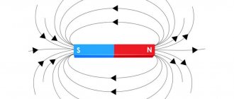
Basic properties of inductance
— The current flowing in the inductor creates a magnetic field with energy. — A change in current in a coil causes a change in the magnetic flux in its turns, creating an EMF in them that prevents a change in current and magnetic flux.
The nature of electromagnetic oscillations in the circuit
Period of free oscillations of the LC
can be described as follows:
If a capacitor with capacity C
charged to voltage
U
, the potential energy of its charge will be.
If you connect an inductor L
, a capacitor discharge current will flow through the circuit, creating a magnetic field in the coil.
An external magnetic flux will create an EMF in the direction opposite to the current in the coil, which will prevent the current from increasing in each turn, so the capacitor will not discharge instantly, but after a time t
1, which is determined by the inductance of the coil and the capacitance of the capacitor based on
t
1 =.
After time t
1, when the capacitor is discharged to zero, the current in the coil and the magnetic energy will be maximum.
The magnetic energy accumulated by the coil at this moment will be. In an ideal consideration, with complete absence of losses in the circuit, EC
will be equal to
EL
. Thus, the electrical energy of the capacitor will be converted into magnetic energy of the coil.
Further, a change (decrease from the maximum) of the magnetic flux of the accumulated energy of the coil will create an EMF in it, which will continue the current in the same direction and the process of charging the capacitor with induced current will begin. Decreasing from maximum to zero over time t
2 =
t
1, it will recharge the capacitor from zero to maximum negative value (
-U
). So the magnetic energy of the coil will be converted into electrical energy of the capacitor.
Described intervals t
1 and
t
2 will be half the period of complete oscillation in the circuit.
In the second half, the processes are similar, only the capacitor will discharge from a negative value, and the current and magnetic flux will change direction. Magnetic energy will again accumulate in the coil during time t
3, changing the polarity of the poles.
During the final stage of oscillation ( t
4), the accumulated magnetic energy of the coil will charge the capacitor to the initial value
U
(in the absence of losses) and the oscillation process will repeat.
In reality, in the presence of energy losses on the active resistance of the conductors, phase and magnetic losses, the oscillations will be damped in amplitude. Time t
1 +
t
2 +
t
3 +
t
4 will be the oscillation period.
Frequency of free oscillations of the circuit ƒ = 1 / T
The frequency of free oscillations is the resonance frequency of the circuit at which the inductance reactance XL=2πfL
equal to the reactance of the capacitance
XC=1/(2πfC)
.
Calculation of the resonance frequency of the LC circuit:
A simple online calculator is provided to calculate the resonant frequency of an oscillating circuit.
You need to enter the values and click in the table. When switching multipliers, the result is automatically recalculated.
Top
Frequency calculation:
| Resonance frequency of the LC oscillating circuit. ƒ = 1/(2π√(LC)) |
Capacity calculation:
| Capacitance for the oscillating circuit LC C = 1/(4𲃲L) |
Inductance calculation:
| Inductance for the oscillating circuit LC L = 1/(4𲃲C) |
Similar pages with calculations:
Calculate impedance.
Calculate reactance.
Calculate reactive power and compensation.
Ideal oscillatory circuit. Thomson's formula
In the last lesson we got acquainted with electromagnetic oscillations. Let us recall that this is the name given to periodic changes over time in electrical and magnetic quantities in an electrical circuit.
Having examined the qualitative side of the theory of processes in an oscillatory circuit, let us move on to its quantitative side. To do this, consider an ideal oscillatory circuit, that is, a circuit whose active resistance is negligible.
In such a circuit, as we showed earlier, the total electromagnetic energy at any moment in time is equal to the sum of the energies of the electric and magnetic fields, and it does not change over time:
And since the energy of the circuit is constant, then the derivative of the total energy with respect to time is equal to zero:
Let us recall that in the written formula, the charge and current in the circuit are a function of time.
To understand the physical meaning of this equation, let us rewrite it as follows:
From this recording it is clear that the rate of change of the magnetic field in absolute value is equal to the rate of change of the energy of the electric field.
And the minus sign in the formula indicates that the increase in the energy of the magnetic field occurs due to a decrease in the energy of the electric field.
Let's calculate the derivatives in the written equation using the formula for calculating the derivative of a complex function.
Now let us remember that the derivative of charge with respect to time is the strength of the instantaneous current (that is, the strength of the current at a given moment in time):
Therefore, the previous equation can be rewritten as shown on the screen:
The derivative of current strength with respect to time is nothing more than the second derivative of charge with respect to time, just as the derivative of speed with respect to time (that is, acceleration) is the second derivative of the coordinate with respect to time:
Let's rewrite the previous equality taking into account this amendment:
By dividing the left and right sides of this equation by "El I" ( Li
), we obtain
the basic equation describing free harmonic electrical oscillations in the circuit:
This equation is similar to the equation describing harmonic mechanical oscillations:
This shows that the reciprocal of the square root of the product of inductance and capacitance is the cyclic frequency of free electrical oscillations:
Knowing the cyclic frequency of oscillations, it is not difficult to find their period, that is, the minimum period of time through which the process in the oscillatory circuit is completely repeated:
This formula was first obtained by the English physicist William Thomson in 1853, and currently bears his name.
It is clear from the formula that the period of the oscillatory circuit is determined by the parameters of its constituent elements: the inductance of the coil and the capacitance of the capacitor.
It also follows from Thomson’s formula that, for example, when the capacitance or inductance is reduced, the oscillation period should decrease, and their frequency should increase, and vice versa.
But let's return to the equation of free electromagnetic oscillations in an ideal oscillatory circuit. Its solution is an equation expressing the dependence of the capacitor charge on time:
In the written formula qm
- this is
the initial (or amplitude) value of the charge
imparted to the capacitor. From this formula it follows that the charge on the capacitor changes with time according to a harmonic law.
If we take the first derivative of the capacitor charge with respect to time, we obtain an equation that describes the change in current strength in the circuit:
A value equal to the product of the maximum charge of the capacitor and the cyclic oscillation frequency is the amplitude value of the current:
Let's rewrite the equation for the current strength taking into account the last equality, and also using the reduction formula:
From this recording it is clearly seen that the current strength in the oscillatory circuit also performs harmonic oscillations with the same frequency, but in phase it is shifted by π
/2 relative to charge fluctuations.
To consolidate the material, we will solve this problem with you. A capacitor with a capacity of 2 μF was charged to a voltage of 100 V, and then shorted to a coil with an inductance of 5 mH. Determine the charge on the capacitor 0.025π ms after the circuit.
In conclusion, we note that in real oscillatory circuits there is always active resistance, therefore part of the energy of the circuit is always converted into the internal conductors, which is released in the form of radiation. In addition, part of the energy is lost due to magnetization reversal of the core and change in the polarization of the dielectric. Therefore, the total energy of the circuit decreases over time, and as a result, the amplitude of the oscillations also decreases. Consequently, real electromagnetic oscillations in the circuit are damped.
How does an oscillation circuit work?
The operation of the oscillation circuit is based on the cyclic conversion of inductive energy into a qualitative indicator of the efficiency of the capacitor and vice versa. Let us assume that the capacitor is fully charged and the energy stored in it is maximum. When you connect it to an inductor, it begins to discharge. At the same time, a current begins to flow through the inductance, causing the appearance of a self-inductive emf, aimed at reducing the flowing current. This means that the process of recharging the capacitor begins. At the moment when the energy of the device becomes zero, the same value for the coil is maximum.
Further, the inductive energy decreases, being spent on charging a capacitor with the opposite polarity. After reducing the self-inductance coefficient to zero, it again has a maximum value on the capacitor.
You might be interested in Description of the KSPV cable
Processes in the system
Important! Ideally, this process can continue indefinitely. In real devices, the oscillation decays at a rate proportional to the losses in the conductor circuit.
Regardless of the amount of energy or the presence of losses, the oscillation frequency is constant and depends only on the values of the parameters of the self-induction coefficient and capacitance. This quantity is called resonant. The resonance formula takes into account the value of the capacitance and inductance of the oscillation circuit.
Oscillogram
When an electrical circuit with a coil is exposed to an external signal with a frequency equal to the resonant one, the amplitude of the change in the position of the particles increases sharply. There is no resonance when the frequencies do not match. Because of the limiting values, an electrical circuit with an inductor is often called resonant.
Losses in the circuit with the inductor (losses in the dielectric of the capacitor, the resistance of the device itself, connecting wires) limit the magnitude of the maximum changes in the direction of the particles. As a consequence of this, a characteristic of the electrical circuit called quality factor was introduced. The quality factor is inversely proportional to the maximum loss value.
Dependence of the limiting frequency on the quality factor
Important! A decrease in the quality factor leads to the fact that the limit for changing directions occurs not only at the fundamental frequency, but also at some approach to it, that is, in a certain frequency band where the resonant value is in the middle. The higher the quality factor, the narrower the frequency band becomes.
Operation of an electric oscillatory circuit
Fig.9. Diagram of a resonant circuit without active resistance in a circuit with a capacitor.
An important feature of current resonance in a parallel oscillatory circuit is that the reactive components of the currents of parallel branches compensate each other, and the currents in these branches usually significantly exceed the current in the unbranched part (the general circuit of the network), then this electrical resonance is called current resonance.
Conclusion. The currents in the parallel branches of the resonant circuit I1 and I2 (see Fig. 6) when the currents resonate separately are as many times greater than the current I0 of the unbranched section of the circuit, how many times the characteristic impedance of the circuit ρ = √ L / C is greater than its active resistance r .
Quality factor or quality of the circuit Q = ρ/ r 1 ( Fig. 9 ). And then the quality factor of the circuit is a value that shows how many times the current in the resonator (resonant circuit) is greater than the current of the unbranched part of the circuit when the currents are resonant. I1/I = I2/I = Q (Fig. 6). The quality of resonators reaches a large value (1,000 or more), so it is important to know the condition for resonance of currents in a parallel circuit.
This is one of the most important properties of the memory structure - resonant recognition of information and speed of thinking.
Unlike voltage resonance (in sensitive systems), with current resonance in the memory structure, the sum of the energies of the electric and magnetic fields of the memory circuit is not a constant value. This means that there are moments when the electrical or magnetic energy of the circuit fields is partially or completely spent in the active resistance of the memory circuit.
There are also periods of time when the memory power source - the sensitive system - replenishes the energy reserve consumed by the electric and magnetic fields of the circuit. However, there is no exchange of reactive energy between the sensitive system and the magnetic energy of the memory structure in a parallel circuit. The sequential oscillatory circuit of the sensitive system, in total, during one oscillation period, delivers to the memory circuit the same amount of energy that was spent in the active resistance of the circuit - for heating during thinking and for emitting electromagnetic waves of thoughts.
It is surprising that the work of the human brain, provided by the reticular formation of the medulla oblongata as a source of the electric field, is exactly identical in detail to the work of a technical parallel oscillatory circuit with current resonance [2].
In reality, every person experiences this phenomenon every night in the mode of so-called rapid (or paradoxical) sleep. Brain neurons in body rest mode (when sensory organs are turned off) are fed by the energy of the reticular formation. And in wakefulness, the sensory organs directly recharge the reticular system, and this repeats throughout life. The brain cannot think without energy, the reticular formation cannot itself generate electrical energy, it needs a sensory system capable of interacting with the electromagnetic environment, converting radiation into currents of the same frequency characteristic of a given type of living being. Therefore, there is a main law in nature - the law of conservation and development of life, carried out through the process of learning the laws of nature and preserving this knowledge.
In conclusion, let's look at how reactive currents change: I1 in a parallel branch with inductance; I2 in a parallel branch with a capacitance; and the total current I in the unbranched circuit of the oscillatory circuit depending on the frequency of forced oscillations ω. Let's consider this for a real case, when the active resistance of the spiral memory structure is small, and in the energy storage circuit it is generally equal to zero (Fig. 10).
I1 = U /ω0 L;
I2 = U / (1 / ω0 C) = U ω0 C.
Rice. 10. Graph of changes in currents I1; I2 in parallel branches of the oscillatory circuit and the total current I, depending on the angular frequency ω.
The current in the parallel branch with inductance I1 (and this is the current of the memory element) varies depending on the frequency of forced oscillations according to the hyperbolic law. At ω = 0, the current in this section is equal to the ratio of the voltage to the small value of active resistance in the inductive circuit. And as ω → ∞, the current I1 tends to zero.
This means that the current in the memory structure I1 decreases with increasing frequency of forced oscillations until it stops completely. That is why high-frequency vibrations coming from the external environment are harmful to the memory structure - it stops thinking. As the frequency of external signals increases, memory stops responding to them, it does not distinguish between their changes, does not develop, and is completely disconnected from them.
In sensitive systems with capacitive properties, on the contrary, with increasing frequency of forced oscillations of the external environment, currents I2 increase to infinity, which is disastrous for the elements themselves. At a low frequency of oscillations of the external wave, the receptors do not perceive this wave; they lose vigilance, not noticing changes.
This also suggests that the sensitive system begins its development with high-frequency signals, gradually moving to lower frequencies. The book of life is read from the beginning, and not from the end, by logical reading of information with an increase in its meaning, i.e. with increasing wavelength.
When the behavior of people is marked by rapidity of spoken language, one should see the end of their evolution.
How does the flow of currents in a parallel oscillatory circuit, especially in its inductive part, depend on the constant frequency of the voltage coming from the sensitive system, but at the same time the value of the electrical capacitance changes? In other words, how does the memory structure react to the electrical capacitance of its power source under conditions of constant signal information from the environment? The course of current changes is shown in Fig. eleven.
Rice. 11. Graph of changes in currents in the memory structure (in the form of a parallel oscillatory circuit) depending on the change in electrical capacitance from zero to infinity.
Current in the inductive memory element I1 = U /ω0L
does not depend on the value of the electrical capacitance (on the size of the power source) in the parallel branch of the circuit at a constant operating voltage of forced oscillations from the sensitive system.
The current in the capacitive circuit I2 increases with increasing value of the capacitance itself: I2 = UωC. At the same time, the memory structure itself does not take more current than it needs. Nature itself shows that the elite by nature, even with the increase in all sorts of benefits, the increase in vital energy (food sources), does not take excesses for itself, being content with the nominal need. The total consumer basket I (Fig. 11) first falls to the optimal growth level of the power source C0, and then rapidly increases. And the mind says that it does not need more than what is necessary. Consumer demand is growing where there is little intelligence, no life experience; the more they have, the more they want to have.
Does every form of matter think or not think? Indirect evidence of thinking for each form of matter is the presence of the frequency of its own undamped oscillations, the presence of its own source of power energy for each memory structure. The energy spent on thinking is compensated by the energy of the power source. If there is a power source, then the form of the substance thinks, no matter how small it may be!
Continuous thought consists of its discrete units. The smallest form of matter, which has the smallest portion of thought, is the universal form of deuterium - a combination of the serial vibrational structure of the hydrogen atom and the parallel vibrational structure of the neutron (universal elementary quadrupole). Atoms of chemical elements represent individual “letters of the general ABC” of life, from which syllables, words, sentences, texts are composed, thought flows, embodied in the forms of matter.
Conclusion
Since all forms of matter and radiation have the same electromagnetic nature of origin, they are all oscillatory systems. All internal processes in the oscillatory system, consisting of a memory structure (inductance) and a sensitive shell (receptors with electrical properties) are electromagnetic. Therefore, we conclude: life has an electromagnetic origin.
Rice. 12. Equivalent diagram of a living material system.
The serial oscillatory circuit L1 C1 - the sensitive system and the parallel oscillatory circuit L2 C2 - form a single whole, a living structural form of matter.
Two Origins, one with magnetic properties of inductance, and the other with electrical properties, form an integral structure, ready for the rhythm of the oscillatory process. Ready, but not yet hesitant.
This system is excited, in the full sense of the word - comes to life, with the arrival of an electromagnetic wave of the corresponding frequency range in its area of residence. A portion of the wave energy breathes life into this form, and a wave-like process of energy transfer from the electrical capacitance to the inductive spiral form of memory and back from the inductance to the capacitance occurs without the participation of the external field of the wave. The independent life of this form of substance has begun, and this oscillatory process can last a long time.
But the external wave came again, and with its voltage excited the sensitive elements of the sequential oscillatory circuit, due to which the weak voltage of the wave increased hundreds of thousands of times. And the amplified voltage, without distorting the meaning, is transmitted to the parallel structure of the oscillatory circuit, where it causes currents flowing along a closed circuit in the mode of undamped oscillations. Thus, the voltage of the external wave is converted into currents of the memory structure, and is stored in the unchanged form of undamped oscillations. The movement of currents forms a magnetic field of the same shape as the current-carrying system. This is how the form of thought is formed outside the circuit of currents.
Energy losses due to thinking require compensation from their energy source, which in turn requires recharging from the sensitive system, and the receptors need the presence of an external electromagnetic field, which is formed by the genetic center of the next level of the hierarchy of forms. This is how life is excited, growth and development occurs under external control to the level of improvement specified by the genome of the external environment.
The purpose of each form of matter is to maintain its internal vibrations within a given range of parameters. If a decrease in EMR of a given level is noticeable in the environment, single related elements are combined on the same principle of dipoles, so systems are formed that are capable of perceiving EMR of long waves and splitting them to the required limit. The live process has begun. So the form of matter becomes a MEASURE of information content in an external electromagnetic field
Test questions for lesson No. 8
1.Why does Life have an electromagnetic origin?
2. How does the versatility of the oscillatory system manifest itself?
3.What is the difference between a parallel and series oscillatory circuit?
4. Explain the process of charging and discharging a capacitor.
5.What is inductance, self-induction, induction?
6.What prevents the memory structure power supply from charging and discharging quickly?
7. How is the existence of a magnetic field related to the dynamics of electric charges?
8. What is the circular frequency and the frequency of natural undamped oscillations? Relationship between frequency and wavelength of radiation through the speed of light. Relationship between oscillation frequency and time and space.
9.What is voltage resonance, where does it occur, and what does it give?
10.Why do all sensitive organs work under strain?
11.What is the reason for receiving and processing electromagnetic information without distortion into the living system?
12. How to explain the individual existence of interdependent elements in a system of bodies and systems among themselves?
13.What is current resonance and who does it belong to?
14. How can we explain superweak interactions in biology and medicine?
15. Tell us the essence of REM or paradoxical sleep in all mammals? Who else might have it?
Is a source of electrical energy needed for the memory structure? The role of protein molecules for the genome is DNA.
[1] Inductance – otherwise known as the coefficient of self-induction, a quantitative characteristic of the relationship between the strength of the electric current in a closed circuit with the magnetic flux through the circuit created by the current in the circuit.
Magnetic induction is a measure of the magnetic state of a magnetic field, a vector quantity.
[2] Tsygan V.N., Bogoslavsky M.M., Knyazkin I.V., Apchel V.Ya. Physiology and pathology of sleep. SPb.: VMA. Special literature. 2006. – 160 p.
Lesson #8. Microsoft PowerPoint presentation.ppt
For beginners about the oscillatory circuit
For beginner radio amateurs, I would like to provide some information about the parameters of oscillatory circuits. After all, inductors are basically their integral part. The circuit, as you know, consists of an inductor and a capacitor. Let's consider a parallel circuit as the most common one.
The main characteristics of the circuit are:
- Circuit resonant frequency
- Circuit quality factor
- Equivalent loop resistance
- Bandwidth
Fig1.
The resonant frequency of the circuit is determined by the formula:
| Where L and C are in Henry and Farad respectively. |
However, you need to remember one very important point. C is not the rated capacitance of the circuit capacitor. It is composed of the sum of capacitances - this capacitor, the parasitic capacitance of the coil, the capacitance of external circuits connected to the circuit (for example, the output and input capacitance of a transistor stage), the parasitic capacitance of the installation. These added capacitances are quite significant, especially at high frequencies, where they are comparable to the capacitance of the loop capacitor itself. They must be taken into account! Sometimes on forums you can read messages like: “I calculated the coil using such and such a program, assembled the structure, and then it turned out that the coils had to be selected using the “scientific poker” method, why such a program if it calculates incorrectly.” The program calculates correctly. She simply considers the “bare” circuit, but the circuit and design of the device must, as a character in a famous film said, be looked at “broader and deeper.”
Theoretically, all of the above applies to inductance L, however, in reality, the inductance introduced into the circuit is an order of magnitude smaller and in most cases can be ignored.
The quality factor of the “bare” unloaded circuit Q is determined by the quality factor of the coil QL and capacitor QC. QL depends on the resistance rL (see Fig. 1.), equivalent to the loss of electrical energy in the wire, in the wire insulation, frame, screen, and inductor core. QL = 2πƒL /rL. Typically, depending on the quality of the inductor design and the materials used, QL≈50÷250.
The quality factor of the capacitor QC Depends on the resistance RC, which is equivalent to the loss of dialectical energy in the capacitor. QC = 1/(2πƒСRC). Usually QC≈400÷1000.
All possible loss resistances (rL, RC) can, for convenience of calculations, be replaced by one resistance Re connected in parallel to an ideal lossless circuit, which is called the equivalent circuit resistance. It characterizes all losses of a real circuit and is equal to the resistance of the circuit at the resonant frequency. In passing, I note that at the resonant frequency the reactances of the coil and capacitor are equal and opposite in sign and cancel each other out, as a result the total resistance of the circuit is purely active. The value of Re is related to other parameters of the circuit by the following relations: Re = 2πf0LQ = Q/(2πf0C), f0 – resonant frequency.
Here again there is an important point. When connecting external circuits to the circuit in parallel with Re, additional resistances introduced by external circuits are connected. At the same time, Re and Q decrease. Moreover, for high-quality circuits, this reduction can be significant. To minimize the influence of external circuits on the circuit, partial switching is used through a capacitive divider, a coil tap, or a coupling coil is used.
The bandwidth is equal to the frequency band where the circuit transmission coefficient is equal to 70.7% of the transmission coefficient at the resonant frequency.
The following relation is valid: Q = f/Δf , which can be used to measure the quality factor of a real circuit.
Does the ratio of inductance to capacitance of a capacitor matter? How to choose the optimal one? The oscillatory circuit is characterized by the parameter ρ = √L/C, called characteristic impedance . This parameter and, accordingly, the optimal L/C ratio depend on the impedances of the circuit in which the oscillatory circuit is included. Approximately in transistor circuits ρ ≈ 500-2000 ohms at HF frequencies and 70-200 ohms at VHF frequencies. As the frequency increases, ρ to reduce the influence of interference and parasitic capacitances of the circuit and to avoid self-excitation.
To summarize, I note that the oscillatory circuit is widely used in radio engineering devices for filtering electrical oscillations, for phase rotation, for matching resistance and for other purposes. When calculating the circuit, it is necessary to take into account the parameters of the external circuits connected to the circuit and the quality characteristics of the circuit parts themselves, especially the inductor .
What is an oscillatory circuit
An oscillatory circuit is several elements in any electrical circuit, capacitance and inductance, which are connected in parallel or in series. For the normal functioning of the oscillatory circuit in the circuit, an energy source is required.
Parallel oscillation circuit
When connecting elements in an electrical circuit in parallel or in series, one or another closed conductor system receives the name of the same name. The phenomenon of resonance in both cases arises in a similar way, only in the case of a parallel oscillatory circuit this indicator relates to the current strength, and in the case of a series one, the maximum frequency of instantaneous voltage changes occurs.
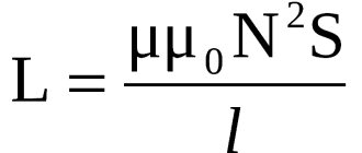
Inductance Formula
The resonance of the oscillatory circuit is calculated based on the values of capacitance and inductance. As a rule, the capacitance of a capacitor is a constant value, with the exception of cases of using variable devices in tunable electrical circuits. The self-inductance coefficient of the coil depends on many factors:
- Number and location of winding turns;
- The presence or absence of a core;
- Core material.
There is no general formula for determining the inductance of an oscillating circuit coil. For calculations, formulas corresponding to the shape of the coil are used. Unfortunately, all formulas for determining the qualitative value of an electrical circuit with an inductor connected to it allow only approximate calculations.
You may be interested in this Features of the Frls cable
Inductance devices of various types
Important! In order to obtain a coil with the given parameters, it is necessary to take additional measures, for example, adjusting the self-induction coefficient by changing the length of the core or adjusting the distance between the turns in single-row coils.