Principle of operation
The main area of application of this device is production. Although they are also installed in everyday life if the owner of a private house has organized a small workshop for himself.
The rules for installing starters are varied. For example, it can be mounted in the machine panel itself, or it can be moved outside of it, in which case it is installed in a distribution panel. The latter are installed in panel rooms. The buttons that control the device are moved outside the boards to any required location. That is, the control itself is performed remotely.
The purpose of an electrical network element is to turn on or otherwise close and open the power supply network. The thing is that other devices of this type, namely switches or circuit breakers, cannot be used in electrical installations, because the latter, when turned on, consume a large starting current, three times the rated current. That is why the starter is connected to the network, because it can withstand these currents.
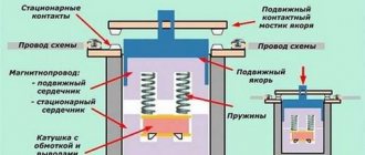
From a purely structural point of view, a magnetic starter is a simple device. It has two types of contacts: moving and fixed. The former are so called because they move with the armature, which moves under the influence of the magnetic floor towards the core when electric current is applied to the latter. The core is located in the coil, and it is itself energized by its own separate circuit to create a magnetic field. It is created precisely inside the coil.
Magnetic starter device Source infourok.ru
Essentially, the operating principle of a magnetic starter is as follows:
- clicked the “Start” button;
- power is supplied to the core and to the moving contacts;
- the core draws the armature into itself;
- he pulls the moving contacts behind him;
- the latter are pressed against the fixed contacts.
If it is necessary to de-energize the electrical installation, the “Stop” button is pressed. It cuts off the power supply to the core. The magnetic field disappears, the armature goes back to its original position, pulling the moving contacts behind it. A gap is formed between the two contact pairs. That is, the supply circuit is interrupted.
It should be noted that the magnetic device itself is not a so-called independent device in terms of functionality. For example, an RCD is such an element of the supply network. The starter is part of the electrical network, which includes this element itself, as well as paired control buttons. Without the latter, it will not work.
Control buttons "Start" and "Stop" Source opt-1362940.ssl
At the same time, it is necessary to highlight the fact that the magnetic starter is a kind of protection of the electric motor from overheating, because it has a thermal relay installed. And if the electric motor starts to operate under heavy load, that is, it starts to overheat, the starter will immediately turn it off automatically.
This device has one more important factor in terms of its installation in the power supply network. Since it is a switching device, that is, powered by buttons, there is no chance that it will turn on spontaneously. For example, if for some reason the mains voltage disappears, any machine will turn off. If there was a regular switch in place of the starter, then the machine would turn on itself if electricity were supplied to the machine again.
Imagine if one of the workers suddenly decided to carry out a small repair of the equipment without turning off the switch. There could have been serious injury. This cannot happen with magnetic starters. Because if you don’t press the “Start” button, the machine will not turn on.
Connection diagrams for a magnetic starter (contactor) and principle of operation
The connection diagram for a magnetic starter (small-sized contactor “KM”) is not difficult for experienced electricians, but for beginners it can cause many difficulties. Therefore, this article is for them.
The purpose of the article is to show as simply and clearly as possible the very principle of operation (operation) of a magnetic starter (hereinafter referred to as MP) and a small-sized contactor (hereinafter referred to as KM). Go.
MP and KM are switching devices that control and distribute operating currents along the circuits connected to them.
MP and KM are mainly used for connecting and disconnecting asynchronous electric motors, as well as their reverse switching using remote control. They are used for remote control of lighting groups, heating circuits and other loads.
Compressors, pumps and air conditioners, heating furnaces, conveyor belts, lighting circuits are where and not only you can find MP and KM in their control systems.
What is the difference between a magnetic starter and a small-sized contactor, according to the principle of operation - nothing. Essentially, these are electromagnetic relays.
The difference found for a contactor - power - is determined by the dimensions, and for a starter - by the values, and the maximum power of the MP is greater than that of the contactor.
Magnetic starter - device and design features
So, contacts were discussed above. Let us add that there are usually either three or four pairs. This block is located inside a plastic case. Insulating cross-beams are located here. The device cover is installed on top. And, of course, inside there is an electromagnetic circuit consisting of a coil, a core and an armature.
There is one more element in this circuit that is not powered by anything. This is a spring. Its purpose is to quickly disconnect the contacts when the current stops flowing to the coil. It is against the spring that the core rests. The thing is that when the contacts open, an electric arc is formed between them. It negatively affects the material from which the contacts are made. That is, the arc will reduce the service life of the latter, and, accordingly, the entire device. Therefore, the faster the opening occurs, the better.
In addition to power contacts, the starter also contains so-called blocking elements. Their purpose is to block any launch actions if the latter is carried out incorrectly.
Note that today manufacturers produce devices of this type in different versions. The most common is with open contacts. In this form there are two modifications, designated as PME and PAE.
Magnetic starter brand PME Source i.simpalsmedia.com
The first ones are installed on electric motors with a power ranging from 0.27-10 kW. The second are 4-75 kW. Both modifications are used in networks with voltages of 220 and 380 V.
As for purely structural design, magnetic starters come in four types:
- open;
- closed, they are also protected or dust-proof;
- dust-splashproof;
- dust and waterproof.
Another difference between PME and PAE is that the former has one two-phase type relay - TRN. In the second, several such relays are installed. Their number depends on the size of the device itself.
Water-dust-proof starter in a casing with buttons Source multiscreensite.com
Connection diagrams
Let's move on to the important part of the topic - connecting the magnetic starter. Here it is necessary to consider two positions that differ from each other in the supply voltage: 220 or 380 volts.
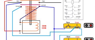
Let us first consider the standard circuit, which is most often used in networks with a voltage of 380 volts. But we note the fact that the coils inside the device can have different voltages: from 12 to 380 volts. Therefore, the schemes may differ slightly.
For example, if the coil is 220 volts. The bottom photo is a wiring diagram for this type.
Magnetic starter connection diagram Source skad.com.ua
In this circuit, a starter with three power contacts and one blocking contact must be installed. It is optimal if a double “Start-Stop” button is installed. You can use two separate buttons, as in the photo and shown.
Pay attention to how the buttons are connected to the device itself - through a blocking contact. Therefore, it is impossible to make a mistake here. The main thing is not to confuse the contacts of the “Start” button with the contacts of the “Stop” button.
Now another question - how to connect a 380V starter with buttons and a 380 volt coil. This circuit is usually used when there is a need to organize protection against a situation where a phase failure may occur. Let us add that this is the simplest scheme. True, it is precisely this that helps protect only two phases. But this is better than being left without three at the same time in case of a break.
Essentially, everything will happen something like this. If one of the phases of the supply network disappears, the starter simply turns off the power supply to the electric motor. And this makes it possible to keep the motor in operating condition.
Connection diagram for a starter with a 380 volt coil Source amperof.ru
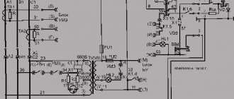
Standard switching diagram for magnetic starters
This starter connection diagram is required in order to start the engine through the starter using the “Start” button and de-energize this engine with the “Stop” button. This is easier to understand if you divide the circuit into two parts: the power circuit and the control circuit. The power part of the circuit should be powered with a three-phase voltage of 380 V, having phases “A”, “B”, “C”. The power part consists of a three-pole circuit breaker, power contacts of the magnetic starter “1L1-2T1”, “3L2-4T2”, “5L3-6L3”, as well as an asynchronous three-phase electric motor “M”.
The control circuit is supplied with 220 volt power from phase “A” and to the neutral. The control circuit diagram includes the “Stop” button “SB1”, “Start” “SB2”, the coil “KM1” and the auxiliary contact “13HO-14HO”, which is connected in parallel with the contacts of the “Start” button. When the circuit breaker of phases “A”, “B”, “C” is turned on, the current passes to the contacts of the starter and remains on them. The supply control circuit (phase “A”) passes through the “Stop” button to contact 3 of the “Start” button, and in parallel to the auxiliary contact of the 13HO starter and remains there on the contacts. If the “Start” button is activated, voltage comes to the coil - phase “A” from the starter “KM1”. The starter electromagnet is triggered, the contacts “1L1-2T1”, “3L2-4T2”, “5L3-6L3” are closed, after which a voltage of 380 volts is supplied to the engine according to this connection diagram and the electric motor begins to operate. When the “Start” button is released, the starter coil supply current flows through contacts 13HO-14HO, the electromagnet does not release the starter power contacts, and the engine continues to operate. When the “Stop” button is pressed, the power supply circuit of the starter coil is de-energized, the electromagnet releases the power contacts, voltage is not supplied to the engine, and the engine stops.
You can also watch the video to see how to connect a three-phase motor:
Rules for installing a magnetic starter
If the device was installed incorrectly, there is a high probability that it will work with false alarms. Therefore, some useful tips:
- Do not install the starter in areas that are subject to vibration or shock loads.
- Installation is usually carried out in an electrical panel. But there are also rules here, the first of which is that the installation site must be flat, vertical and level.
- It should not be exposed to heat from any sources. This may cause the thermal relay to trip on its own.
- The switchboard cannot be installed in rooms where there is electrical equipment with a current higher than 150A. the whole point is that starting and stopping such equipment is accompanied by a shock.
- If one end of the wire is inserted into the contact clamp, then it must be bent in the shape of the letter “P”.
- If two ends of the wire are inserted into the clamp at once, then they are installed on both sides of the screw, and they must be straight, not bent.
- Before making the first start, the magnetic starter must be checked for technical condition and for correct connection of the contacts.
Installation is carried out in the switchboard Source tehnormal.by
Schemes for connecting magnetic starters
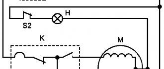
One of the simplest magnetic starter connection diagrams is shown below:
The principle of operation of this circuit is quite simple: when the QF circuit breaker is closed, the power supply circuit for the magnetic starter coil is assembled. The PU fuse provides short circuit protection for the control circuit. Under normal conditions, the thermal relay contact P is closed. So, to start the asynchronous machine, we press the “Start” button, the circuit closes, current begins to flow through the coil of the magnetic starter KM, the core is retracted, thereby closing the power contacts of the KM, as well as the block contact BC. The block contact BC is needed in order to close the control circuit, since the button, after it is released, will return to its original position. To stop this electric motor, just press the “Stop” button, which will disassemble the control circuit.
In case of prolonged current overload, the thermal sensor P will be triggered, which will open contact P, and this will also lead to the machine stopping.
When using the connection diagram above, you should take into account the nominal voltage of the coil. If the coil voltage is 220 V, and the motor (when connected in a star) is 380 V, then this circuit cannot be used, but can be used with a neutral conductor, and if the motor windings are connected by a delta (220 V), then this system is quite viable.
Circuit with neutral conductor:
The only difference between these connection schemes is that in the first case, the control system power is connected to two phases, and in the second to a phase and a neutral conductor. When automatically controlling the starting system, instead of the “Start” button, a contact from the control system may turn on.
You can see how to connect a non-reversible magnetic starting device here:
The reversible connection circuit is shown below:
This circuit is more complex than when connecting a non-reversible device. Let's look at the principle of its operation. When you press the “Forward” button, all the actions described above occur, but as you can see from the diagram, a normally closed contact KM2 appears in front of the forward button. This is necessary to electrically block the simultaneous activation of two devices (avoiding short circuits). When you press the “Back” button while the electric drive is running, nothing will happen, since the KM1 contact in front of the “Back” button will be open. To reverse the machine, you must press the “Stop” button, and only after turning off one device can you turn on the second.
And a video of connecting the reversible magnetic starting device:
What is the difference between magnetic starters and contactors?
Both devices are switching devices, that is, they control power networks. And more often they are installed in the electric motor starting system. In both devices, in addition to power contacts, there is at least one, and often more, which is used for the control circuit.
Otherwise they differ. Firstly, in size and weight. Starters are much more compact. At the same time, their weight is much less. For example, if you take both devices of the same rating in different hands, the contactor will be many times heavier. In addition, it should be noted that contactors that would be designed for low currents simply do not exist. They are replaced in power networks by starters.
Secondly, it's all about the design. Contactors are open type devices. They do not have a body or lid. Therefore, the installation and connection of contactors is carried out in special rooms, which must be locked with a key. Outsiders are prohibited from entering such premises. In addition, they are well protected from precipitation. The design of contactors contains arc-extinguishing chambers.
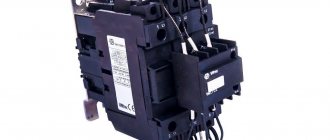
Contactor for power circuit Source dc-electro.ru
The latter are not included in the starters. But this variety is equipped with a sealed case closed with a lid. There are modifications located in metal casings. Therefore, the starters can be installed anywhere, even outdoors.
Thirdly, the magnetic starter has three pairs of power contacts in its design. Therefore, their main purpose is to control electric motors. Contactors are designed to control any type of electrical circuit. Therefore, the number of power contacts in them can vary in the range of 2-4.
There are no other differences.
Magnetic starter device
All types of magnetic starters are united by such design elements as an alternating current electromagnet, a system of moving and fixed power and auxiliary contacts. The supporting part is a body made of heat-resistant and non-flammable plastics. These plastics must be mechanically strong and not deform at elevated temperatures. Any starter is usually three-phase.
- Contact springs for smooth starting
- Moving contacts (bridges)
- Fixed contacts (plates)
- Plastic traverse
- Anchor
- Starter coil
- W-shaped part of the magnetic circuit
- Additional contacts
The classification of magnetic starters is made according to several criteria, among which the main one is usually the size of the starter. The value does not mean the dimensions or weight of the starter, but what current it can switch and how resistant it is to an arc in circuits with inductances (when the electric motor is turned off). The basis is a non-reversible magnetic starter, since the reversible ones are assembled from the latter. Magnetic starters operate under different conditions, so they are also classified according to the degree of protection: open, protected, dust-splash-proof.
The operation of a magnetic starter very often requires a thermal relay. All types of magnetic starters have structurally compatible thermal relays. They are often produced by the same manufacturer. A particularly important application of thermal relays is to protect electric motors from overheating. The thermal relay consists of two-phase bimetallic conductors (conductors with different coefficients of thermal expansion) - one for each phase.
From an electrical point of view, they are resistors with very low resistance, and thus serve as current sensors. When too much current flows through the phases (or one of them), the bimetallic strip bends and opens the magnetic contacts, that is, the contacts in the starter coil circuit. Thermal relays are connected between the starter and the load.
Modular starters are becoming more and more common. These are DIN rail mounted starters. This is a metal profile strip fixed in cabinets on a panel. The simplicity and ease of installation are exceptional. Next to the starter (contactor) you can attach thermal relays, circuit breakers, RCDs (residual current devices), microprocessor controllers and much more. Modular devices are very easy to assemble into circuits, thanks to the wire channels laid between the DIN rails. Installation is carried out with stripped wires of the required cross-section and crimped lugs. The tips are inserted into the holes of the device terminals according to the circuit diagram and clamped with screws.
Markings required for installation and repair are applied to the top side of the starters. There is a type designation, a contact diagram and in some cases manufacturers leave space for a sticker or signature of consumer data.
Great advances in power electronics over the past decades have meant that most major manufacturers now offer consumers contactless starters containing high-power semiconductor switches. They have certain advantages. They operate silently, do not spark, and have a high switching frequency.
Some models, thanks to PWM controllers, allow smooth starting of electric motors, and even network interfaces are provided for automation. Disadvantages include high price, highly qualified repair personnel and unsafe galvanic connection to the network, which can threaten repair electricians.
Briefly about the main thing
Magnetic starter is a switching device for controlling a power network. Namely, starting and stopping electric motors.
Magnetic starter device: three pairs of power contacts, a coil with a core to which an armature is connected. The latter is connected to a block of moving contacts.
The starter is connected via the start-stop button.
Although the starter performs the functions of a power network contactor, it is not a contactor, because it is very different from the latter in its design form and current rating.
Ratings 0
Components of the apparatus
First of all, let's look at the device of the magnetic starter. In fact, the design is not complicated and includes a movable and a fixed part. To make the information more clear, let’s consider the design of the device, based on the PME series model:
PME apparatus design
- Contact springs, which ensure smooth closing of the contacts when the starter is turned on, and also create the necessary pressing force.
- Contact bridges.
- Contact plates.
- Plastic traverse.
- Anchor.
- Winding.
- W-shaped part of the core (fixed)
- Additional contacts.
In addition, the magnetic starter device may include shock absorbers, the purpose of which is to soften the shock during startup of the device. In the PM12 series, shock absorbers are designated by the number 8, but they are shown more clearly in the second picture - the design of the PAE-311 magnetic starter (designation “10”).
PAE-311
We told you what a magnetic starter consists of, but it’s unlikely that this would give you anything to understand, especially if your level of knowledge is “a kettle in electrics.” To make everything fall into place, next we will look at the principle of operation of the device.