A magnetic starter is a switching device with which, at a distance, you can repeatedly turn on and off a consumer (electric motors, electric heating elements, electric boilers, and so on). Before understanding the topic of the article - the starter connection diagram, you need to understand the principle of its operation.
Magnetic starters are mainly used today to control asynchronous motors. It is used to “start”, “stop” and reverse the motor. But there is one more point that should not be overlooked. This is an opportunity to relieve low-power electrical networks where conventional circuit breakers (circuit breakers) are installed. In order to understand this, it is necessary to give an example.
If a 10 ampere circuit breaker is installed in the distribution board, then its throughput power is calculated according to Ohm's law: P=UI=220x10=2200 W or 2.2 kW. In fact, such a machine can withstand lighting in which there are twenty-two light bulbs of 100 watts each. To increase the power consumption of an electrical chain, for example, by two times, you should not divide it into sections where you will have to install several circuit breakers and install separate electrical wiring. It is enough to install a magnetic starter, for example, of the third magnitude.
This device has contacts rated at 40 amperes. Hence the ability to withstand power consumption: 40x220 = 8800 W or 8.8 kW. That is, by connecting 88 100 W bulbs in series, you can turn them on and off simultaneously with one click.
The design of the magnetic starter is based on an electromagnetic coil. So, at the moment of startup (switching on), the device consumes 200 watts. In operating condition, the power does not exceed 25 W. Even if you calculate the current strength at the time of start-up, there will be insignificant parameters: 200 W / 220 V = 0.9 amperes. That is, this value is enough for the device to turn on the main electrical circuit. It turns out that even the smallest magnetic starter can easily control the machine. In this case, there will always be a reduced current on the contacts of the latter, which will not lead to their burning. This means that the circuit breaker will turn off quite large powers with its contacts.
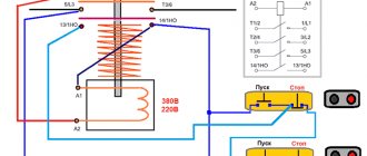
Attention! There are several types of magnetic starters, in which the coil is designed for different voltages. These are 220 volts, 380 and 36.
Connection diagrams
So, now let’s move on to the main topic of the article – starter connection diagrams. There are two of them:
- Reversible.
- Irreversible.
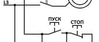
How to connect a non-reversible circuit. It is standard when the electric motor connected to the network rotates in one direction.
The diagram clearly shows that the motor is started by the “Start” button located on the magnetic starter KM 1. In order not to hold this button, it is bridged with the contacts of the device. That is, when you press the “Start” button, it closes the contacts of the starter, through which current will be supplied to the electromagnetic coil of the device.
Switching off is done with the “Stop” button. On the starter diagram it is indicated by the letter “C”. This button simply opens the contacts. In this case, the core returns to its normal state under the action of the springs, and the electric motor is turned off.
In principle, the thermal relay, indicated in the starter connection diagram with the letter “P,” works in exactly the same way.
Operating principle of an asynchronous motor
The electric motor can operate in both three-phase and single-phase modes . The operating principle of the circuits changes slightly, but there are some additions to the power supply from a single-phase network.
Three-phase network
The electrical circuit diagram of the reversible start of a three-phase electric motor with a squirrel-cage rotor is as follows (the diagram is shown in Fig. 1) The entire circuit is powered from a three-phase alternating current network with a voltage of 380 V through an automatic circuit breaker.
In order to reverse such an electric machine (M), you need to change the alternation of any two phases connected to the stator. In the diagram, magnetic starter Mn1 is responsible for forward rotation, and Mn2 is responsible for reverse rotation. The figure shows that when Mp1 is turned on, the phases on the stator A, B, C alternate, and when Mp2 is turned on - C, B, A, that is, phases A and C change places, which is what we need.
When voltage is applied to the circuit, the coils Mp1 and Mp2 are de-energized. Their power contacts Mn1.3 and Mn2.3 are open. The electric motor does not rotate.
When you press the Start1 button, power is supplied to the MP1 coil, the starter is triggered and the following happens:
If there is a need to stop the engine or reverse , you need to press
Stop button. In this case, the power circuit Mn1 opens, the contactor is turned off, its contacts return to their original state shown in the figure, and the electric motor stops.
In order for the engine to start rotating in the opposite direction, you need to press the Start button2. By analogy with Mp1, contacts Mp2.3, Mp2.1, Mp2.2 will operate, a phase switch will occur on the stator winding and the motor will begin to rotate in the opposite direction.
The control circuit is powered from two phase wires. With this connection, contactors with 380 V coils must be used. Fuses Pr1 and Pr2 provide protection against short circuit currents. In addition, removing these fuses completely de-energizes all controls and avoids the risk of electrical injury during maintenance and repair.
Protection of the electrical machine from overloads is provided by thermal relay RT . When an increased current flows in any of the three stator windings, the bimetallic plate RT heats up, causing it to bend. At a certain current, the plate heats up so much that its bending causes the thermal relay to operate, due to which it opens its normally closed contact PT in the control circuit of the coils Mp1 and Mp2 and the motor is disconnected from the network.
The response time depends on the current value: the higher the current, the shorter the response time. Due to the fact that the RT operates with a certain delay, inrush currents, which can be 7-10 times higher than the rated ones, do not have time to trigger the protection.
Depending on the type of device and settings, after the thermal relay is triggered, there are two options for returning the circuit to working condition:
The considered three-phase motor reverse circuit can be modified depending on conditions and needs. For example, the control circuit can be powered from a 12 V network, in which case all control elements will be under safe voltage and such an installation can be safely used in high humidity.
Reversing the motor can only be done when the motor is completely stationary, otherwise the starting currents will increase several times, which will lead to the protection being triggered. In order to monitor the fulfillment of this condition, time relays can be added to the control circuit, the contacts of which are connected in series to MP2.2 and MP1.2. Thanks to this, after pressing the Stop button, the engine can be started in the opposite direction only after a few seconds have passed, which are necessary to completely stop the mechanism .
Single phase mode
In order for a three-phase asynchronous motor with a squirrel-cage rotor to operate from a single-phase 220 V network, a connection diagram with starting and running capacitors is used.
Three wires come from the stator winding of the electric motor. Two wires are connected directly to the phase and neutral wires, and the third is connected to one of the supply wires through a capacitor. In this case, the direction of rotation depends on which of the supply conductors the capacitor is connected to.
If you want to turn such a connection diagram into a reversible one, it needs to be supplemented with a toggle switch that will switch the capacitance from one power wire to another.
Reversible circuit
In fact, this circuit, regardless of the size of the starter, works similarly to the previous one. Of course, it is more complex, because it adds another button - reverse, and another magnetic starter.
Reverse itself is the reconnection of two phases in places. But here it is necessary to observe one point - it is necessary that the second starter does not turn on at this time. That is, it needs to be blocked. According to the diagram, it is clear that if two starters turn on at the same time, a short circuit will occur.
Here are the dynamics of the circuit:
- the QF automatic switches on;
- press the “Start 1” button;
- voltage is supplied to the electric motor, which begins to work.
When reversing, the following happens:
- the “Stop 1” button is pressed, with which the electric motor is disconnected from the power supply;
- then you need to press the “Start 2” button, which supplies voltage to KM 2;
- The engine starts to work only its rotation changes to the opposite.
Both considered connection diagrams apply to three-phase consumers. Two-phase systems are no different from them in operating principle. True, the connection diagram here is simpler. Here is this non-reversible scheme:
Selecting a magnetic starter
The main characteristic that you need to focus on is the size of the starter, which is selected depending on the load current. Here it must be taken into account that the current for which the power contacts of the starter are designed must be greater than the maximum load current.
For example, to select a contactor for controlling an asynchronous motor with a squirrel-cage rotor, first of all we need to determine the technical parameters of the motors, such as:
- η – efficiency (Engine efficiency)
- cos Ф – power factor
- P – rated engine power
- U – operating voltage
The rated current of the starter is determined by the formula:
Inom=P/ (U*η* cosφ*√3)
Next, we determine the starting current
Istart = k* IN
k is the multiple of the starting current to the rated current, that is, how many times the starting current will exceed the rated current when starting the engine. This parameter influences the choice of the starter application category, for example, category AC-3 can withstand a starting current 5-7 times higher than the rated current.
Based on these calculations, we select a starter with a rated current greater than the calculated one and the required category of application.
In addition, we select the operating voltage of the coil - it must be the same as that of the control circuits, the degree of protection, the presence of auxiliary make or break contacts, and the wear resistance class.
Specifications
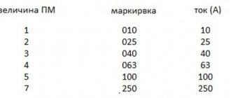
We will not consider all the parameters of the device here, because the choice is always made based on the size of the starter, which is characterized by the rated load current acting on the contacts of the device. There are seven starter values, each of which corresponds to the permissible current load. The photograph below shows these same values and in what areas such magnetic starters are used.
It should be noted that small errors in the parameters are acceptable. But in some cases it is necessary to take into account the range in which the thermal relay operates. If the starters have an overestimated load, and the relays have an underestimated minimum thermal shutdown value, then there may be a mismatch with the specified power of the electrical circuit or consumer.
Magnetic starter device
Structurally, the magnetic starter consists of a double housing, an upper part in which there is a moving part of the magnetic circuit (armature) with an attached traverse with spring-loaded moving contacts and fixed contacts, and a lower part in which there is a control coil, a return spring and a fixed part of the magnetic circuit (core) with short-circuited turns necessary to reduce vibrations.
The moving and stationary parts of the magnetic circuit must have a smooth, polished surface without any contamination, otherwise the starter will produce a strong hum during operation.
When voltage is applied, an electromagnetic field appears in the control coil, under the influence of which the armature is attracted to the core, and the main and auxiliary contacts are closed. When the voltage is removed, the coil is de-energized, the armature, under the action of the return spring, returns to its original position, the contacts open and the circuit is de-energized.
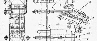
Reversible starting circuit for an asynchronous electric motor
As promised in the previous article, I present a diagram for reversing starting of an asynchronous motor using two magnetic starters.
Principle of operation
similar to irreversible starting, so we will not go into detail.
The main difference is the use of additional blocking contacts KM1:5
and
KM2:5
.
It is known that to change the direction of rotation it is necessary to change the phase sequence (in the above diagram, phases A
and
C
).
And if both magnetic starters are turned on simultaneously, a short circuit will occur on the contacts of the magnetic starter KM1:1.
3 /
KM2:1.
3. To protect against accidental reverse switching on in the power supply circuit of KM1
and
KM2
normally closed contacts
KM1:5
and
KM2:5
.
For example, when you press the SB2:1
“Forward ”
KM1:5
open , and only then the power contacts
KM1:1 close.
3 and contact block
KM1:4
.
Pressing the SB3:1 “Back ”
will not turn on the second magnetic starter, and, consequently, to a short circuit.
To start the engine in the opposite direction, you must stop the engine by pressing the SB1:1
“Stop ” button.
It is also possible to vary the above circuit using locking contacts on buttons rather than on magnetic starters.
As you can see, the difference in the scheme is minimal. Only the work is different. Now, to change the direction of rotation, there is no need to press the SB1:1
“Stop ”
.
For example, if the engine rotated "forward"
, then when you press the
SB3 “Back ”
, first of all the blocking contact
SB3:2 will open,
which will turn off the magnetic starter
KM1
, and only then the contacts
SB3:1
, which will turn on the starter
KM2.
And finally, the appearance of the control box, assembled according to the described scheme:
Source
Reversible connection diagram for a magnetic starter
Electric motors are used overwhelmingly for drive mechanisms and independent units. When it is necessary to change the direction of rotation of its shaft, a reversing starter is used for starting, the connection diagram of which is the object of study by professionals and ordinary people.
- How does a starter work and what is it used for?
- Difference between direct and reversing starters
- Type and operation of a 220 V reversible circuit Operating principle