Schemes for connecting magnetic starters
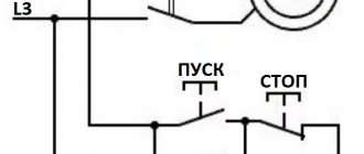
One of the simplest circuits for connecting a magnetic starter is shown below:
The principle of operation of this circuit is quite simple: when the QF circuit breaker is closed, the power supply circuit for the magnetic starter coil is assembled. The PU fuse provides short circuit protection for the control circuit. Under normal conditions, the thermal relay contact P is closed. So, to start the asynchronous machine, we press the “Start” button, the circuit closes, current begins to flow through the coil of the magnetic starter KM, the core is retracted, thereby closing the power contacts of the KM, as well as the block contact BC. The block contact BC is needed in order to close the control circuit, since the button, after it is released, will return to its original position. To stop this electric motor, just press the “Stop” button, which will disassemble the control circuit.
In case of prolonged current overload, the thermal sensor P will be triggered, which will open contact P, and this will also lead to the machine stopping.
When using the connection diagram above, you should take into account the nominal voltage of the coil. If the coil voltage is 220 V, and the motor (when connected in a star) is 380 V, then this circuit cannot be used, but can be used with a neutral conductor, and if the motor windings are connected by a delta (220 V), then this system is quite viable.
Circuit with neutral conductor:
The only difference between these connection schemes is that in the first case, the control system power is connected to two phases, and in the second to a phase and a neutral conductor. When automatically controlling the starting system, instead of the “Start” button, a contact from the control system may turn on.
You can see how to connect a non-reversible magnetic starting device here:
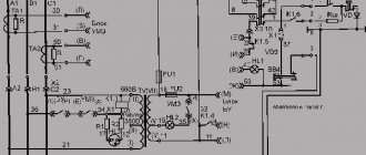
The reversible connection circuit is shown below:
This circuit is more complex than when connecting a non-reversible device. Let's look at the principle of its operation. When you press the “Forward” button, all the actions described above occur, but as you can see from the diagram, a normally closed contact KM2 appears in front of the forward button. This is necessary to electrically block the simultaneous activation of two devices (avoiding short circuits). When you press the “Back” button while the electric drive is running, nothing will happen, since the KM1 contact in front of the “Back” button will be open. To reverse the machine, you must press the “Stop” button, and only after turning off one device can you turn on the second.
And a video of connecting the reversible magnetic starting device:
When installing magnetic starting devices with thermal relays, it is necessary to install with a minimum difference in ambient temperatures between the electric motor and the magnetic starting device.
It is undesirable to install magnetic devices in places subject to strong shocks or vibrations, as well as near powerful electromagnetic devices whose currents exceed 150 A, since they create quite large shocks and jolts when triggered.
For normal operation of the thermal relay, the ambient temperature should not exceed 40 0 C. It is also not recommended to install it near heating elements (rheostats) and not install them in the most heated parts of the cabinet, for example at the top of the cabinet.
Comparison of magnetic and hybrid starters:
A reversible magnetic starter is used to start an asynchronous electric motor in two directions of rotation - forward and reverse. I recommend reading about the technical characteristics and how the magnetic starter works in ours.
Circuit short circuit protection
As already stated before, before carrying out the phase change process, it is necessary to stop the rotation of the motor. For this purpose, the system takes into account normally closed contacts. Because if there is a shortage of them, operator inattention would lead to an interphase direct short circuit, which can occur in the motor winding of the second and third phases. The proposed model is considered optimal, since it allows the operation of only one magnetic starter.
The connection diagram of a reversible magnetic starter is considered the core of the control, since a lot of electrical equipment operates in reverse, and this device directly changes the direction of rotation of the motor.
Reversing circuits of electromagnetic starters are installed where they are actually needed, since similar devices exist, and the reverse process is unacceptable and can cause serious automatic damage.
Specifications
Purpose, design and operation of a magnetic starter
We will not consider all the parameters of the device here, because the choice is always made based on the size of the starter, which is characterized by the rated load current acting on the contacts of the device. There are seven starter values, each of which corresponds to the permissible current load. The photograph below shows these same values and in what areas such magnetic starters are used.
It should be noted that small errors in the parameters are acceptable. But in some cases it is necessary to take into account the range in which the thermal relay operates. If the starters have an overestimated load, and the relays have an underestimated minimum thermal shutdown value, then there may be a mismatch with the specified power of the electrical circuit or consumer.
{SOURCE}
Magnetic starter device for reverse starting
Headphone connection diagram
Starting a motor using a star-delta circuit When starting powerful three-phase electric motors directly using a reverse control circuit, voltage drops occur in the network
If you look at the diagram again, you will notice that the KM1 starter has a direct phase connection to the motor, and KM2 provides some bias
Switching on the engine via an electromagnetic starter provides, in addition to all the convenience of control, zero protection. The internal circuitry of the reversing device is characterized by the fact that it is impossible to run two modes at the same time - direct and reverse. Now look at the KM2 contacts.
Action with a certain time delay prevents mechanical damage and eliminates strong voltage surges when connected to a load source with inductive characteristics.
How does motor protection occur during irreversible starting? Protection of an electric motor is implemented using bimetallic contacts TP, they bend as the current increases, and the release acts on the contact in the starting winding, stopping the supply of electrical energy. It removes the reactive component from the network, resulting in a reduction in load and, as a consequence, current consumption.
In a similar way, by closing the existing contact KM1, the effect of self-capture of the magnetic device occurs. This is due to the large inrush currents flowing at this moment. At the conclusion of this article, watch a video demonstrating the detailed operation of the engine reverse starting circuit. I highly recommend reading it before further reading.
It is better not to skimp on connection components, because this is a so-called push-button post. In the starter, the coil in the metal core is directly responsible for switching the power contacts, to which the armature is pressed, pressing on the contacts and closing the circuit. The simplest engine control circuit is shown in Fig.
In all the diagrams given in this article, electromagnetic starters have a coil for voltage V. When a change in the direction of rotation of its shaft is required, a reversible starter is used for starting, the connection diagram of which is the object of study by professionals and ordinary people. When using low-power motors that do not require starting current limitation, starting is carried out by turning them on at full mains voltage.
Power and blocking contacts can be normally open or normally closed. Changing the direction of rotation of the engine and associated actuators is a fairly popular procedure. The reversing starter consists of two ordinary starters assembled according to a special circuit. Electrical circuit of the hoist
Reversing magnetic starter circuit
Pass-through switch connection diagram for 1 lamp
It will not be difficult for most people to assemble the circuit on their own. The only thing you must take into account is that you cannot do the mechanical locking yourself; you need a factory-made device. In principle, a properly assembled electrical lock will be sufficient.
Let's start looking at the description of the circuit from the power section. The machine comes with three different phases. Yellow "A", green "B" and red "C". Next they go to the power contacts of two starters designated KM1 and KM2. On the other hand, 3 jumpers are made between the central green phases, and between the yellow on the first and red on the second, and also between the red on the first and yellow on the second.
Next, the phases go to the electric motor through a thermal relay, which controls the current in only 2 phases. There is no need to control the thirds, because all three phases are closely interrelated. Simply put, an increase in current in one causes the same in the other. If the current consumed by the motor increases beyond safe limits, the power supply circuit of both coils is opened at once.
The control circuit performs the function of turning on/off the power contacts KM1 and KM2. It consists of buttons, a block of contacts and a coil, which, when voltage is applied to it, draws in an armature that closes the contacts. When it is turned off, KM1 or KM2 opens under the action of the return spring.
The described circuit has a 380 Volt coil, which is powered from 2 different phases. If the operating voltage on the coil is 220 Volts, then use any one phase and zero to connect.
In our case, one green phase goes directly through the thermal relay contact to the first contacts of both coils.
The other phase to the second contacts goes through the common “Stop” button. And then jumpers are made to the constantly open contacts of the “Forward” and “Back” buttons. From there, wires are connected to the corresponding starters to the open contacts in the off state - KM 1.3 and KM 2.3. And on the second side of these contact blocks, wires are respectively connected to the second contacts of the start buttons.
But in order for there to be an electrical lock, it is necessary to connect the wire from the start buttons to the coil not immediately, but through the permanently closed contacts of another starter.
When turned on, the constantly open ones close, and the constantly closed ones, on the contrary, open. Previously, all block contacts were made on the side of the starter. Today, for the permanently open one, the fourth one next to the 3 power contacts is used. And for a permanently closed one, a special attachment is used on top of the power ones. Example in the picture.
What causes the reversible switching of a three-phase motor?
You might be interested: What is simplification?
First, let's take a superficial look at what causes the reverse? It is caused by the swapping of two wires, usually in the branded engine box.
In the photo: a sample of a branded box with a star connection.
In the figure above we see that the beginnings of the windings (C1, C3, C5) are free to be connected to the network. The ends of the windings (C2, C4, C6) are connected together.
In the photo: connection with direct connection of the engine to the network.
In the figure, colored circles indicate contacts for connecting phases. Phase A is indicated in yellow, and it is connected to contact C1, phase B (C3) is green, phase C (C5) is yellow.
Observing the above conditions, we will swap any 2 phases and connect as follows. Phase A remains in its place, contact C1, phase B is placed on contact C5, and phase C is placed on contact C3.
In the photo: star connection with reverse connection.
Thus, it turns out that we need 2 starters. One starter is required to provide direct switching, and the second is required for reverse switching.
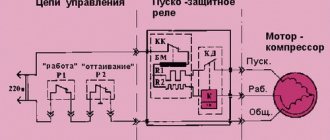
Type and operation of a 220 V reversible circuit
In this wiring diagram you can see the following main elements (indicated by numbers):
- Blocking or blocking contacts;
- Magnetic starter coils designed for a supply voltage of 220 V;
- Thermal or current protection contacts (relay elements);
- Starter power contacts.
Our readers recommend!
To save on electricity bills, our readers recommend the Electricity Saving Box. Monthly payments will be 30-50% less than they were before using the saver. It removes the reactive component from the network, resulting in a reduction in load and, as a consequence, current consumption. Electrical appliances consume less electricity and costs are reduced.
Type of reversible circuit for 220 V
In addition, alphanumeric designations distinguish:
- MP-1, MP-2 – magnetic starters. Their boundaries are indicated by dashed lines in the diagram;
- Stop, Start – controls (the block itself is highlighted with a dashed line). Only the Stop button is highlighted separately. The start buttons (forward and reverse) are designated as two pairs of contacts connected to the MP-1 and MP-2 starters;
- M – electric motor.
Operating principle
As you can see, three opposite phases from the 380 V network are supplied to the power contacts of the starters. There is no designation in the diagram above, but in other cases you can find the symbols A, B, C or L1, L2, L3. A block connection is organized by direct jumper of the central phases of the relay, as well as diagonal jumpers of the side phases (conditionally 1 phase MP-1 is connected to 3 phase MP-2, etc.).
After this, the wires go to the electric motor M. At this interval, a thermal relay is connected to the open circuit. It monitors two of the three phases to cut off power to the motor in the event of an overload.
The control unit with start buttons is connected from one of the central phases to the thermal relay open, and the neutral wire (ground) from the PML starter coils. Protection against simultaneous activation of starters is organized by cross-connecting the contacts of the start/reverse buttons with the blocking contacts of the opposite contactor.
When turned on from the forward control unit, the contacts close to the first starter, which starts the engine. At the same time, the contacts of the second starter open, and the proper voltage does not flow to the coil.
Reverse is turned on after stopping the engine with the Stop button and then pressing reverse. Thus, we have reversed side phases on the coils, which leads to the motor rotating in the opposite direction. Blocking of the first starter occurs according to a similar principle.
Starter capabilities
To limit the starting current of a three-phase motor, its windings can be connected in a star, then, if the motor has reached its rated speed, switch to a delta. In this case, magnetic starters can be: open and in a housing, reversible and non-reversible, with and without overload protection.
Each electromagnetic starter has blocking and power contacts. Power switches loads. Interlocking contacts are needed to control the operation of the contacts. Blocking and power contacts can be naturally open or normally closed. In circuit diagrams, contacts are shown in their normal state.
The ease of use of reversing starters cannot be reviewed. This includes operational control of three-phase asynchronous motors of various machines and pumps, and control of the ventilation system, fittings, right down to the locks and valves of the heating system. The possibility of remote control of starters is especially noteworthy if the electrical source of remote control switches the starter coils in a similar way to relays, and the latter safely connect power circuits.
Basic operating principles
The reversing starter is based on an electromagnetic three-pole AC contactor
This part is considered the most important, and it is also the one that ensures the performance of all functions that relate to working with rated current and voltage, as well as the switching capabilities of the starter and its resistance to mechanical wear
The reversing starter can operate in several modes:
- the first operating mode is called “long-term”;
- the second operating mode is intermittent-continuous;
- the third mode is intermittent;
- The last operating mode of the starter is short-term.
To find out the duration of activation of each individual reversing starter model, you must refer to its technical characteristics, which are attached to each product.
Design and principle of operation
Magnetic contactors or starters refer to switching devices that remotely start electric motors and other equipment.
The design and circuit of these devices is very similar to an electromagnetic relay
An important additional function is the ability to promptly connect and disconnect a three-phase load. The main structural element is a magnetic core made in the shape of the letter Ш
The material used was electrical steel in the form of thin sheets.
The core itself consists of two halves, one of which is stationary and is fixed to the base of the device. The other part - the movable one - in the absence of current is held at a certain distance from the fixed part by a spring. This creates an air gap between both parts.
The starter is controlled through a coil placed on the central rod of the core, located in the stationary part. Contacts are attached to the moving magnetic circuit through a bridge connection. At the moment the starter is triggered, these bridges move simultaneously with the magnetic circuit and make a short circuit with the fixed contact group.
The starting device is triggered after voltage is applied to the control coil. An electromagnetic force arises, under the influence of which the moving part of the core is attracted to the stationary part. As a result, the power contact groups become closed, and current begins to flow to the output terminals. After the voltage supply is stopped, the coil is de-energized and the moving part returns to its place. At this moment, the return spring is activated, ensuring the opening of the contacts.
During switching off, a double gap is formed at each pole of the contacts, facilitating more efficient extinguishing of the electric arc. The function of the arc chute is performed by the device cover, under which the contacts are located.
The starter has not only the main contact group, but also an additional one - in the form of block contacts, used for auxiliary purposes. They are mainly used in control, signaling and blocking circuits.
How does a starter work and what is it used for?
As can be logically determined from the name, this device is designed to start electric motors of various drive mechanisms and equipment.
This is specific equipment that is necessary for switching power purposes with large loads, both direct and alternating current. The starter has wider functionality than the basic contactor and, in addition to providing frequent starts and stops, can act as a protective barrier during overloads. In addition, reversing and non-reversing starters, for example, the PML series, have found their application in organizing remote control circuits, starting pumping, ventilation, crane units, air conditioners, etc. Any magnetic starter consists of the following main parts:
- Electromagnetic part. It consists of a coil and disconnected magnetic circuits - a fixed core and a movable armature,
- Main contact block. They are needed to close/open powerful power loads. Taking into account the parameters of the starter, it can have up to 5 pairs of contacts. One half of them is located on the anchor crossbeam, and the other half is located on the upper part of the hull,
- Blocking contacts. They are used when switching control circuits of a circuit, for example, when starting/stopping occurs using start buttons. The main contacts are blocked, which means that the need to hold the control button is eliminated,
- Return mechanism. Essentially, it is just a spring that, when the contacts open, returns the armature to its original position, providing the necessary gap between the pairs.
Reversing starters with mechanical interlocking PML
The use of this type of reversing starters is also carried out where it is necessary to monitor the starting, reversing and stopping of an asynchronous three-phase motor.
The design of these devices is considered quite simple. The body is made of plastic, and inside there is an anchor and a core. A special pull-type coil is installed on the core. Due to the design features of this device, it turns out that the entire upper part of the body is occupied by traverse guides, above which the anchor is installed. In addition, special bridges with springs are also mounted near this element, which are designed to block the product.
The operating principle of this device is quite simple. When current is applied to the device, voltage accumulates in the coil, causing the armature to begin to be attracted to it. When these two parts are closed, the armature opens the closed contact and closes the open one. The PML reversing starter is turned off at the moment when the contacts open.
Required Components
Independently connecting the motor for reverse rotation will not cause any particular difficulties if you follow the diagram provided. One of the important components that will facilitate this task is a magnetic starter or contactor. In fact, a magnetic starter and a contactor are not identical concepts. To put it simply, the contactor is part of the magnetic starter, but for simplicity, in the article both concepts are used as equivalent. Magnetic starters are precisely used for starting, reversing and stopping asynchronous motors.
Perhaps the question arises as to why you can’t use a regular switch or power circuit breaker. In principle, this is acceptable, but the starting currents that the engine needs for normal operation are not always safe for humans. When switched on, a breakdown may occur, which will damage both the switch and harm the operator. To minimize risks, you will need a starter. In it, the contact part is separated from the one with which the operator interacts. It contains a separate module with a coil that creates an electromagnetic field. The coil may require 12 volts or more to operate. When this voltage is applied, it interacts with the metal core, which is pulled into the coil. A plate is attached to the core, which goes to the contact group. They close and the engine starts. Stopping occurs in reverse order.
In addition to the contactor, you will need a three-button station. One key performs the stop function, and the other two start functions with a difference in the direction of rotation. A three-button station must have two normally open contacts and one normally closed. Simply put, the normal position of the contactor is its non-operating position. That is, when a contact is acted upon, it either closes or opens. If in operating condition it is closed, it is designated as NO, and if it is open, it is designated as NC. The NC contact is used for the stop button.
Reversible circuit for connecting an electric motor through starters
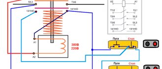
In some cases, it is necessary to ensure that the motor rotates in both directions. For example, for the operation of a winch, in some other cases. A change in the direction of rotation occurs due to phase reversal - when connecting one of the starters, two phases must be swapped (for example, phases B and C). The circuit consists of two identical starters and a button block, which includes a common “Stop” button and two “Back” and “Forward” buttons.
To increase safety, a thermal relay has been added, through which two phases pass, the third is supplied directly, since protection in two is more than enough.
Starters can be with a 380 V or 220 V coil (indicated in the specifications on the cover). If it is 220 V, one of the phases (any) is supplied to the coil contacts, and “zero” from the panel is supplied to the second. If the coil is 380 V, any two phases are supplied to it.
Also note that the wire from the power button (right or left) is not fed directly to the coil, but through the permanently closed contacts of another starter. Contacts KM1 and KM2 are shown next to the starter coil
This creates an electrical interlock that prevents two contactors from being supplied with power at the same time.
Since not all starters have normally closed contacts, you can take them by installing an additional block with contacts, which is also called a contact attachment. This attachment snaps into special holders; its contact groups work together with the groups of the main body.
The following video shows a diagram of connecting a magnetic starter with reverse on an old stand using old equipment, but the general procedure is clear.
Add site to bookmarks
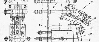
Connection diagram for a three-phase asynchronous motor, in the starting position of which the stator windings are connected by a star, and in the operating position by a triangle.
There are six ends suitable for the engine. The KM magnetic starter is used to turn the motor on and off. The contacts of the magnetic starter KM1 work as jumpers to turn on the asynchronous motor in a triangle
Please note that the wires from the motor terminal block must be connected in the same order as in the motor itself. The main thing is not to confuse
The KM2 magnetic starter connects jumpers for star connection to one half of the terminal block, and voltage is supplied to the other half.
When you press the “START” button, power is supplied to the KM magnetic starter. It is triggered and voltage is supplied to it through the block contact. The button can now be released. Next, voltage is applied to the radio, it counts down the set time. Also, voltage is supplied through the closed contact of the time relay to the magnetic starter KM2, and the engine starts in the “star”.
After the set time, the RT time relay is activated. Magnetic starter P3 is turned off. The voltage is supplied through the time relay contact to the normally closed (closed in the off position) block contact of the magnetic starter KM2, and from there to the coil of the magnetic starter KM1. The electric motor is connected to a triangle.
The KM2 starter should also be connected through a normally closed contact block of the KM1 starter to protect against simultaneous activation of the starters.
It is better to take double magnetic starters KM1 and KM2 with a mechanical lock for simultaneous activation.
The “STOP” button turns off the circuit.
The scheme consists of:
- Circuit breaker.
- Three magnetic starters KM, KM1, KM2.
- Start-stop button; - Current transformers TT1, TT2; - Current relay RT; - Time relay RV.
- BKM, BKM1, BKM2 are block contacts of their starter.
More about deadlock
The electrical circuit for reversing starting of an asynchronous motor requires an interlock. It is worth understanding that to change the direction of rotation of an asynchronous motor, you need to swap any 2 phases. To do this, the starter inputs are connected directly, and the output is connected crosswise across any 2 phases. If both starters are turned on at the same time, a short circuit will occur, which will most likely burn out the power contact groups on the starters.
You may be interested in: Boyle-Mariotte Law: formula and example of a problem
In order to avoid a short circuit when installing a reversible motor start, it is necessary to prevent the simultaneous operation of both starters. This is why it is necessary to use an interlocking scheme. When the first starter is turned on, the power to the second starter is interrupted, which prevents its accidental activation, for example, both “start” buttons are pressed simultaneously.
If it turns out that when you press the button that should turn on “rotation to the right,” the engine rotates to the left, and, conversely, when you press “rotation to the left,” the engine rotates to the right, you should not reassemble the entire circuit. Just swap 2 wires at the input - that's all, problem solved.
It may happen that this is impossible to do at the input due to some circumstances. In this case, swap the 2 wires in the brand box on the engine. And again the problem is solved. The right spin button will spin right, and the left spin button will spin left.
Reversible circuit
In fact, this circuit, regardless of the size of the starter, works similarly to the previous one. Of course, it is more complex, because it adds another button - reverse, and another magnetic starter.
Reverse itself is the reconnection of two phases in places. But here it is necessary to observe one point - it is necessary that the second starter does not turn on at this time. That is, it needs to be blocked. According to the diagram, it is clear that if two starters turn on at the same time, a short circuit will occur.
Here are the dynamics of the circuit:
- the QF automatic switches on;
- press the “Start 1” button;
- voltage is supplied to the electric motor, which begins to work.
When reversing, the following happens:
- the “Stop 1” button is pressed, with which the electric motor is disconnected from the power supply;
- then you need to press the “Start 2” button, which supplies voltage to KM 2;
- The engine starts to work only its rotation changes to the opposite.
Both considered connection diagrams apply to three-phase consumers. Two-phase systems are no different from them in operating principle. True, the connection diagram here is simpler. Here is this non-reversible scheme:
This one is reversible:
Protection of motor reverse operation
Always, before changing the order of connecting a 3-phase motor, changing the order of phases on the windings of the electric motor, it is necessary to stop it. This is implemented in the switching circuit by normally closed contacts, which “safeguard” the operator’s work and prevent phase-to-phase short circuits in the electric motor when its connection is reversed. In the considered connection diagram for the reversing starter, it can be seen that only one starter can operate.
Every day there is work to connect direct and reverse rotation electric motors; the circuit diagram for switching on the starters is not difficult for qualified electricians. It must always be remembered that the function of stopping the engine must be implemented before it rotates back.
Similar articles:
- Single-phase electric motors 220V
- What is soft starting of an electric motor?
- What is a stepper motor and how does it work?