Technical characteristics and markings
Despite the fact that the operating principle of all magnetic starters is the same, certain types of this device have a number of technical differences. To identify design features and performance characteristics, there is a system of symbols for these products. For example, you can take the specific PM marking.
PM12-025 2 4 1 UHL 2 B
PM12 – product series. All products in this series have the same housing and actuator design. The housing dimensions may vary depending on the current load. The more powerful the starting device, the larger its size.
PM12-025 _ _ _ UHL _ _ (first three digits), 025 – rated load on power contacts – up to 25 Amperes. A PM with such a current characteristic is classified as a magnetic starter of magnitude 2. PM12, depending on the size, can provide operation of electric motors, the current range of which is from 10 to 250 Amperes.
Table of correspondence of markings to the operating current load of the PM
PM12 ___ 2 _ _ UHL _ _ (fourth digit), 2 irreversible starter, equipped with a thermal relay to protect the electric motor from long-term current overloads in the event of a break in one phase, as well as in the event of jamming of the drive or driving mechanism. The purpose of starters and the presence of thermal protection is determined by the following marking system:
PM12 ___ _ 5 _ UHL _ _ (fifth digit), 5 degree of protection IP20, open design, without shell. Prevents foreign mechanical objects from getting inside the device and accidental human contact with active and live parts. A magnetic starter made with this degree of protection is not protected from the ingress of water or other liquid into it, therefore, as a rule, it is placed in lockable electrical panels on DIN rails. The bulk of electrical devices that are most widely used have a degree of protection IP20.
PM12 ___ _ _ 1 UHL _ _ (sixth digit) design according to the number of block contacts, 1 – 2 normally open (open) and 2 normally closed (closed).
Marking on magnetic starter PM12
PM12 ___ _ _ _ UHL 2 _ (UHL) design of electrical equipment for moderately cold climates, UHL 2 - intended for operation in rooms without heating or under a canopy.
PM12 ___ _ _ _ UHL _ B (B) performance characteristics for wear resistance. A – 320 thousand cycles, B – 100 thousand cycles, C – 30 thousand cycles.
For the convenience of the average consumer, the manufacturer often, in the marking established by standardization requirements, additionally indicates the rated current characteristics of the starter, the type of current, as well as the operating voltage of the magnetic coil. Below, in highlighted text, the load characteristic is indicated - 25A, voltage - 380V and alternating current - AC.
PM12-025 2 4 1-25A-380AS-UHL2-B
Alternating current is indicated by the symbol AC, direct current by DC. The pull-in coils of PM12 starters are, in most cases, designed to operate on alternating current with a voltage of 24V, 220V or 380V.
Types and applications of magnetic starters
Installation of startersMagnetic starters
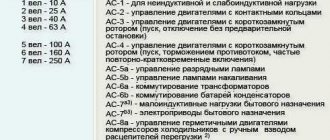
Magnetic starters are produced in both non-reversing and reversible versions. Starters of the PME type are used when starting low-power motors, and are used in electrical circuits for electric motors:
- 127V – from 1.1 to 3 kW;
- 220V – from 1.1 to 5.5 kW;
- 380V – from 4 to 10 kW;
- 500V – 10 kW;
- 660V – 7 kW
In the mid-80s, PME starters began to be replaced by starters of the PME-M series.
Magnetic starters
types PA and PAE are necessary to start medium-power electric motors:
- 127V – from 4.5 to 7.5 kW;
- 220V – from 10 to 40 kW;
- 380V
- 500V - from 17 to 75 kW.
Starter modifications are indicated by numbers that indicate:
- the first is the size of the starter;
- the second is the type of execution (1 – open, 2 – protected, 3 – dust and waterproof);
- third - irreversible or reversible, the presence or absence of a thermal relay (1 - non-reversible without a thermal relay, 2 - non-reversible with a thermal relay, 3 - reversible without a thermal relay, 4 - reversible with a thermal relay).
In an example it looks like this:
- PME-111 – magnetic starter of the first magnitude in an open design, irreversible, without a relay;
- PA-423 – magnetic starter of the fourth magnitude, manufactured in a protected design, reversible, without a relay;
- PA-312 is a magnetic starter of the third magnitude, manufactured in an open design, irreversible, with a thermal relay.
Since the 80s, PAE magnetic starters have been replaced with improved analogues of the PMA series.
The PMA and PML series of magnetic starters are designed for currents from 6.3 to 160A at voltages up to 660V. Installation of starters
This type is carried out to start high power asynchronous motors - up to 90 kW. They are equipped with three-pole electrical and thermal relays, which makes it possible to prevent overloads of unacceptable duration, including protection against two-phase operation. Magnetic starters of the PMA and PML series are produced in both open and protected versions, irreversible or reversible, with the ability to switch the connection diagram from star to delta. The switching wear resistance of these devices for category AC-3 is from 2 to 3 million VO cycles. Mechanical wear resistance – from 10 to 16 million VO cycles.
Thyristor starters are used to control three-phase electric motors located in stationary or mobile installations. Their power part is made of thyristors, which are connected in back-to-back parallel pairs for each phase. The starter should be installed in a vertical position, but deviations from vertical up to 45° in any direction are allowed. The starter can operate in both continuous and intermittent modes with a switching duration of 60% and a switching frequency of up to 600 times per hour. The devices have thermal protection against possible overloads, as well as maximum current protection, the operating threshold of which can be adjusted. The starter is controlled using buttons with or without latching the command. Control using contactless logic elements is also possible.
© All materials are protected by the Russian Federation copyright law and the Civil Code of the Russian Federation. Full copying is prohibited without permission from the resource administration. Partial copying is permitted with a direct link to the source. Author of the article: team of engineers from OJSC Energetik LTD
Device and principle of operation
Today, manufacturers have launched the production of magnetic starters, which are used in all areas of industry, transport, and everyday human activity. They differ in design, complexity of the control circuit, overall dimensions, magnitude of current loads, degree of protection from the influence of the external environment, but they are all united by the fact that their operation is based on one principle.
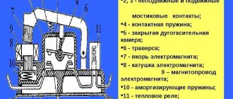
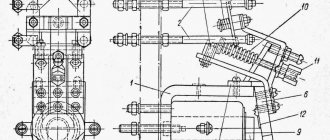
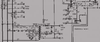
Figure 1 Design of a magnetic starter of the PM12 series
The plastic housing of the magnetic starter consists of two parts (2) and (3). In the lower part (3) there is the main working element - the magnetic system of the starting device, consisting of a retractor coil (6), an armature (4) and a core (7), assembled from W-shaped plates made of electrical steel.
A retractor coil (6) and a return spring (11) are placed on the middle core of the fixed core (7), which is attached to the body (3) with a plate (8). In order to soften the dynamic load, a shock absorber (8) is installed between it and the iron of the core.
The body has special guide grooves along which the traverse (1) makes reciprocating movements. The movable part of the magnetic system (armature) and the starter contact bridge (12) are rigidly attached to the traverse
A short-circuited coil (5) is attached to the outer cores of the core in special grooves, ensuring gentle operation of the coil.
When current passes through the turns of the coil, a field is created, under the influence of which the moving part of the magnetic system of the actuator is drawn into it. The movement of the armature towards the coil carries along the traverse along with the device for closing and opening the power and auxiliary contacts of the starter. When the PM is de-energized, the return spring returns the armature to its original position, which will cause the contacts to open.
At the base of the housing there is a clamp designed for quick-release fastening of the starter to the DIN rail.
Basic connection diagrams for starters
In practice, three main types of starter connection schemes are used: direct, reversible and star-delta. Each of them, in turn, can be divided into subtypes depending on the voltage.
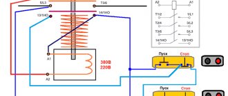
Non-reversible circuit
This technique is used if there is no need to change the direction of rotation of the engine during operation. In the basic version, for 220 volt coils, such circuits will look like:
The same circuit, but for 380 volt coils:
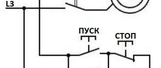
Each of them includes the following elements:
- Automatic switch (QF),
- Magnetic starter (KM1),
- Blocking contacts (BC),
- Thermal protection relay (P),
- Asynchronous type motor (M),
- Safety element (PR),
- Controls or buttons (Start, Stop).
After connecting the power through the QF circuit breaker, the Start button is pressed, which closes the contacts and supplies voltage to KM1. It puts the engine into operation. After this, the Start button can be released, as the blocking on the BC contacts will work. The power is turned off automatically when the voltage drops (the BC holding contacts open) or overload (the thermal relay or fuse trips). You can also stop the voltage supply manually using the Stop button.
Reversible circuit
When there is a need to change the direction of rotation of the electric motor, reverse is used, which is based on the starter unit. Device connection diagrams for 220 and 380 volts will look like this:
Reversible circuit scheme No. 1
Reversible circuit scheme No. 2
As you can see, the same elements are present here as in non-reversible circuits, but another starter (KM2) and a button to start it (Start2) have been added. Changing the direction of rotation occurs due to a change in phases. But there are a number of key points to consider, including preventing two switches from being turned on at the same time to avoid a short circuit. When voltage is applied through the QF machine, the start button on the first contactor (Start1, KM1) is turned on. At the same time, the normally closed contacts BK1 in front of the reverse button are split. Reverse is activated in the same way, through Start 2, but before that you need to turn off the power - Stop (C).
Star and triangle combination diagram
Star and delta circuits are the most common when connecting a motor to an electrical line. In the first case, it will work smoothly, but will not be able to develop full power. The triangle connection, in turn, does not give such even revolutions, but allows you to develop full power, up to one and a half times the nameplate.
In high-power engines, an interesting move is often used: the initial smooth input is organized along a star, and after reaching the required speed, they automatically switch to a triangle. This allows, among other things, to significantly reduce the consumed starting currents. An approximate circuit for switching on the starter and time relay in this mode will look like this:
Types of electromagnetic starters
In fact, there are a great many of them, but we will focus on the PM series... PMA - the main purpose: starting, stopping, assembling reversible circuits for starting three-phase asynchronous low-voltage AC electric motors.
PME - these starters are intended for use in stationary installations for remote starting by direct connection to the network, stopping and assembling reversing circuits of three-phase asynchronous electric motors with a squirrel-cage rotor of alternating voltage 660 V, frequency 50 and 60 Hz. The presence of three-pole thermal relays of the RTT and RTL series PME starters makes it possible to protect controlled electric motors from long-term overloads and from overflows that occur when one of the phases is broken.
PM-12 - this type is intended for remote switching on and off, assembling reversing circuits for low-voltage asynchronous AC electric motors and other electricity consumers. KMI starters, manufactured by IEK, operate in AC-1, AC-3 (described above) and AC-4 modes (starting by direct connection to the power supply, achieving rated speed, operating mode, stopping and reversing asynchronous electric motors (for reversing connect two identical contactors, provide a mechanical relationship that does not allow simultaneous activation).
In fact, the series of these starters differ in installation option, IP protection level, and wear resistance. KME can be called a separate series. This is a complete device that is immediately supplied in a box; depending on the design and purpose, a further abbreviation is “selected”.
Specific types of starters and their operation schemes
In addition to typical tasks, these devices, due to their functionality, can be used in more specific conditions. Let's consider them briefly using the example of a thyristor starter, explosion-proof switches such as PVR-125r and PVI-250 V, connections through thermostat contactors and the organization of automatic transfer switches.
Thyristor starters and their connection circuit
The peculiarity of this type of starting relay is that they do not use the method of direct physical breaking of the circuit. That is, they are non-contact and, in principle, do not have the key disadvantages of conventional devices (mechanical wear of contacts, arc formation, etc.). You can turn on the electric motor correctly using thyristor DC devices, the connection diagram of which is as follows:
The following elements are involved in the circuit:
- L1, L2, L3 – phase wires (poles),
- TA1, TA 2 – current transformers,
- R1, R 2 – resistors,
- VD1, VD 2 – transistors,
- VS1…VS6 – thyristors,
- CU - control unit,
- SB1, SB2 – “Start” and “Stop” buttons.
Starters type PVR-125r and PVI-250 V
Electric motors are used not only in conditions that are more or less familiar to us: for example, at various mining enterprises, mines, etc., where there is a potential explosive atmosphere, dust and other negative factors. Consequently, the design of starting devices must provide for such situations. In such conditions, relay modules PVR-125r and PVI-250 V (BT) are used.
The PVR type starter is a reversible modular unit, which is mounted in an explosion-proof housing. It is used to commission three-phase electric motors of various mining equipment operating in coal mines. PVRs are subject to special requirements in terms of combating methane and dust.
Starter PVR-125r
The PVI-250 V starter (BT, D) is used in the same conditions as PVR, but based on the marking it also has spark protection. Designed to turn on and off the engines of mining equipment. Through PVI-250 additional protection is provided against possible short circuits or overloads in the network.
Starter PVI-250 V
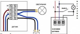
Connecting thermostats using start relays
A warm floor or infrared heater is additionally equipped with thermostats to maintain the required temperature background. They can be used not only on a domestic, but also on an industrial scale. An approximate connection diagram for such a system, when the circuit thermostat is connected not directly, but through a contactor, looks like this:
Formation of automatic transfer switches on starters
Another case where the use of switches is in demand is the installation of ATS (emergency transfer switch) systems. This increases the reliability of power supply, since there are at least two sources. You can correctly organize the input node on the ATS according to the following scheme:
Here you can see two power supplies (1 and 2), circuit breakers on each of the lines (AB1, AB2), starters and their contact units (PM1 and PM2). In case the power sources are not completely independent (for example, one of the lines comes from a conditional neighbor), the circuit provides a voltage control relay RKN, which selects a guaranteed input line.
Starting magnetic devices are one of the most important elements for the correct commissioning of electrical equipment, in particular synchronous motors, including in hazardous mine conditions (we are talking about PVR and PVI contactors). The connection can be organized in a direct, reverse or combined circuit (star-delta). In addition, starters are widely used in other areas where there is no need to use motors, for example, for organizing the supply of power to home networks or to heating systems using thermostats, a direct or backup source (AVR).
Magnetic starters
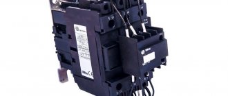
A magnetic starter is a low-voltage device of a combined type and electromagnetic principle, which starts electric motors, ensures their continuous rotation, disconnects them from the power supply, protects, and performs reversing functions.
Principle of operation
This device consists of a main part for stationary mounting, a coil, an armature that moves along the guides of the mechanism, a spring mechanism, stationary and moving contacts and a housing. The simplest starters appear in the form of a box equipped with a button and terminals for connection to power circuits and stationary contacts.
The principle of operation is that when current enters the starter coil, it is triggered according to the principle of an electromagnet. Under the influence of a magnetic field, the armature is attracted to the core, as a result of which the contact bridge closes and the electrical equipment starts up. The lower position of the armature affects the operation of the entire device. In this position, there must be reliable contact between the contacts, since this component plays the role of a strong connection of the input and output electrical wires at the moment the circuit operates.
The absence of current entails the disappearance of the magnetic field around the coil. This leads to the armature being thrown upward due to the energy of the springs; the contact bridge located on the moving part ensures a break in the power circuit, which leads to a shutdown of power and equipment. This system also has auxiliary block contacts.
The serviceability of magnetic starters can be checked manually. If the device is working properly, then when you press the anchor, you should feel resistance from the compression of the springs. This manual control is only valid for checks and is not used during the work process.
Application area
The main area of use of magnetic starters is starting, stopping and reversing asynchronous electric motors. And, since these devices are quite unpretentious and protected from environmental influences, they are installed for remote control of lighting equipment, compressor units, pumps, cranes, electric furnaces, conveyors, and air conditioners.
The use of DIN rails for fastening
Often the starter is connected via a DIN rail. In this case, a special modular type device is used together with it. DIN rail is a metal profile that is used to connect modular equipment. The equipment is mounted in cabinets, special installation boxes, as well as on electrical panels.
DIN rails of various widths are used in industry. The distances between their mounting holes may also differ.
Starter prices
A large number of starters of various series are produced in our country. Many of them are designed for 220V power supply. Their prices vary over a fairly wide range. It depends on the design of the device and its technical characteristics.
The size (power) of the PM has the greatest influence on the price. For home use, it is advisable to purchase a starter with a current load of 25 A and a degree of protection IP54, which provides complete protection against accidental contact with active parts and the ingress of dust, moisture and liquid into it.