Field of application of reed switches
Contact groups on reed switches are actively used in electrical circuits of security alarms. A group of contacts on reed switches in one housing can simultaneously make switches in several electrical circuits not connected to each other. In alarm systems, this is used to turn on sound and light indications of operation, and to transmit signals to the duty control panel.
An example of installing reed switches in the control panel of a mobile fuel pumping station
At enterprises with explosive impurities, reed switches are effectively used for switching electrical equipment for various purposes, since when closing and opening contacts there are no sparks extending beyond the sealed glass flask of the housing. To start powerful electric motors, reed switches are used that are capable of connecting circuits with a load of up to 45 kW.
In addition to low-voltage equipment, there are models of reed switches that are used to close circuits with voltages from 1000 V to 100 kV, in relay protection of high-voltage overhead lines for transmitting electricity. Arc-extinguishing structures and damping devices are installed on such elements to dampen vibration vibrations of the contacts. Reed products for switching provide the opportunity to develop new directions in instrumentation, automatic control and protection devices in relay systems.
Disadvantages of reed relays
- Low sensitivity of MDS control of reed relays.
- Susceptibility to external magnetic fields, which requires taking special measures to protect against external influences.
- Fragile reed relay cylinder, sensitive to shock.
- Low power of switched circuits for reed switches and gersikons.
- Possibility of spontaneous opening of contacts of reed relays at high currents.
- Inadmissible opening and closing of reed relay contacts when powered by low frequency alternating voltage.
Over the decade of virtual downtime of the domestic relay industry, the Russian market has been filled with foreign analogues of reed relays (mainly German, Chinese, Taiwanese), their use has become common in electrical installations.
Basically, such relays are structurally produced on the basis of a reed switch with cut leads located inside the control winding, with a reed switch and a coil welded to the terminals of the technological frame, which, after crimping with special plastic and cutting out jumpers on the frame, form the relay itself.
Operating principle of reed switches
The work is based on the use of magnetic field forces arising between ferromagnetic elements in the reed switch. These forces can deform and move the ferite contact plates, causing them to close or open. The magnetic field for magnetizing ferromagnetic contacts in the area where the device is located is created in two ways:
- A coil wound on the body, to which direct current is supplied;
A coil wound on a glass bulb of a reed switch
Tip No. 1, you can regulate the magnetic flux yourself by winding the wire around the coil body until the contacts are activated
- External permanent magnet.
On the left side of the picture, the permanent magnet is removed and the reed switch contacts return to their original position.
On the right side, the magnet is brought to the reed switch, the magnetic field switches the contacts.
The simplest design of a reed switch
Design and principle of operation of reed switches
The reed switch consists of two ferromagnetic plates, usually made of steel and nickel, sealed in a glass capsule. The plates are placed so that they overlap, providing a small air gap, and close in the presence of a magnetic field of appropriate strength. The contact area of both plates has a sprayed or galvanic coating made of a very resistant metal (usually rhodium, ruthenium). The structure of the contact coating layers is shown in Figures 2 and 3 for rhodium and iridium, respectively.
Rice. 2. Structure of the NiFe-W-Ru contact group
Rice. 3. Structure of the NiFe-Au-Ro-Ir contact group
Iridium and rhodium are very resistant to erosion metals. They make it possible to ensure long operating time of contacts if they do not switch a very powerful load. The capsule cavity typically contains nitrogen or similar inert gas. Some types of reed switches are evacuated to increase the switching voltage potential. The plates of a reed relay behave like a magnetic circuit: when an external magnetic field is applied from a magnet or electromagnetic coil, mutual attraction of the plates occurs. The generated fields with the opposite sign ensure that the contacts close when the magnetic force exceeds the return force of the contact plates. When the strength of the external magnetic field decreases so that the force between the contacts becomes less than the return force, the contact opens.
The reed switch described above and presented in Figure 1 is characterized as 1 Form A (normally open or unipolar unidirectional SPST contact group).
Rice. 1. The device of a simple reed switch with a contact group of type A (normally open contacts)
Multidirectional switches of this configuration are described as 2 Form A (two normally open contacts or a bipolar unidirectional DPST relay), a 3 Form A relay has three normally open contacts, and so on. The normally closed contact is described as 1 Form B. A relay with a changeover contact is shown in Figure 4 and is characterized as a single-pole bidirectional (SPDT) 1 Form C.
Rice. 4. Three-terminal reed switch device type 1 Form C (unipolar bidirectional)
The main types of contact groups used for both reed switches and reed relays are given in Table 1.
Table 1. Main types of contact groups of reed switches and reed relays
| Name, type of contact group | Electrical diagram of the contact group* |
| 1 Form A | |
| 1 Form B | |
| 1 Form C | |
| 3 Form A | |
| * – other combinations of the number and type of contact groups for reed switch relays are also possible. However, for single reed switches, only single contact groups of 1 Form A, 1 Form B or 1 Form C are used. | |
The common plate is the only moving part of this type of reed switch and is closed to the normally closed relay contact in the absence of a magnetic field. When a magnetic field of appropriate strength occurs, the common contact closes with the normally open contact. Both plates of the normally open and normally closed contacts are stationary. All three plates have a ferromagnetic coating, but the contact area of the normally closed contact is made of non-magnetic material welded to the ferromagnetic plate. When placed in a magnetic field, both terminals assume the same polarization, opposite the moving contact. The non-magnetic material interrupts the magnetic flux in the normally closed contact, and the movable contact is attracted to the normally open contact, forming with it a continuous magnetic circuit for the magnetic flux.
Triggering of a magnetically controlled contact can be achieved in two ways:
- using a magnetic field created by a permanent magnet (Figure 5);
Rice. 5. Operating principle of a magnetically controlled contact - reed switch
- using a magnetic field created by an inductor (Figure 6).
Rice. 6. Interaction of a permanent magnet with a magnetically controlled contact: a) parallel orientation of the permanent magnet, b) perpendicular orientation of the permanent magnet
When a permanent magnet approaches a magnetically controlled group of contacts, each plate becomes magnetized. In this case, the force of their mutual attraction arises. When the magnetic field force reaches a threshold value exceeding the elasticity of the contact plates, they close. When the external magnetic field disappears, the residual magnetic field in the ferromagnetic contact plates also dissipates, causing them to open. If there is a residual magnetic field on the contact plates, the characteristics of the reed switch will be different from those specified during production. Therefore, in their manufacture, high-temperature annealing is used to remove the residual magnetic field.
The magnetic characteristic of the contact group of magnetically controlled contacts has a pronounced anisotropic symmetrical directionality. Figure 6 shows a diagram of the interaction of a permanent magnet with a magnetically controlled contact, a “reed switch”.
Let's take a closer look at this interaction.
Since the reed switch contacts have their own sensitivity diagram, then, depending on the location of the magnet and its orientation in space relative to the contact group, three interaction options are possible:
- the magnet is out of range (Figure 6a, positions 1, 5; Figure 6b - positions 1, 5, 8);
- magnet in the trigger zone (Figure 6a, position 3; Figure 6b - positions 3, 4);
- the magnet is in the hysteresis zone (Figure 6a, positions 2, 4; Figure 6b - positions 2, 4, 7).
In Figure 6, solid lines show the zone of reliable operation of the contact group. When a permanent magnet is within its limits, the magnetic field is sufficient for reliable operation of the contact group. The dotted line shows the hysteresis zone - when a magnet enters this zone, the magnetic field is not yet strong enough to trigger the contact group, but it is still sufficient to keep the contact group in the “triggered” state. In the case of a different configuration of the reed switch contact group, different from the considered 1 Form A, “triggering” will be understood as opening the group 1 Form B or switching 1 Form C. Moreover, the sensitivity diagram is different for parallel (Figure 6a) and perpendicular (Figure 6b) orientation of the constant activator magnet relative to the contact group of the reed switch.
Based on this principle of operation of a magnetically controlled sealed contact group, there are several ways to control a reed switch, presented in Figure 7.
Rice. 7. Methods of controlling a magnetically controlled contact
Figure 7a, c, d shows methods for controlling the contact group of a reed switch using a rotating permanent magnet, and the number of operations per revolution of such an activator will be determined by the number of poles of the activator magnet.
Figure 7b shows the method of angular movement of the permanent activator magnet.
In Figure 7d, the magnet is stationary - the curtain moves, shielding the magnetic field of the activator - a permanent magnet.
The main types of reed switches produced by Standex-Meder Electroincs are shown in Table 2.
Table 2. Main types of single reed switches
| Name | Appearance and dimensions, mm | Power dissipation, W | Switching voltage, V | Switched current, A | Application |
| KSK-1A35 | 0…20 | 0…200 | 0…1 | General, automotive equipment | |
| KSK-1A46 | 0…10 | 0…200 | 0…0,5 | instrumentation | |
| KSK-1A66 | 0…10 | 0…200 | 0…0,5 | General, automotive equipment | |
| KSK-1A87 | 0…10 | 0…200 | 0…0,5 | General, automotive equipment, instrumentation |
When using single reed switches, it should be remembered that a significant excess of the permissible switching current through the contacts can lead to their spontaneous opening, burning and, as a result, failure of the reed switch. This also applies to the reed relays based on magnetically controlled contacts considered below.
Types of reed relays
The great demand for the use of reed switches in a wide variety of industries, taking into account production conditions, gives rise to a large number of product models. All reed relays can be divided by type of contact:
- With open contacts in the initial state;
- With closed contacts in the initial state;
- With combined groups of contacts, when normally closed and open reed switches are located in one housing.
Based on their design, reed relays are divided into two types:
- Dry - with the flask filled with an inert gas or with a vacuum inside, this is done to increase the resistance of the contacts to high current loads;
- Wet - reed switches have liquid metal at the points of contact; mercury acts as a shock absorber during vibration, preventing opening.
Ferrite Reed Relays
This is a special class of reed relays with ferrite cores. They have a memory function. To make a switch in reed switches of this type, you need to apply a current pulse of reverse polarity in order to demagnetize the ferrite core. They are called memory hermetic contacts, or gelawns. Advantages of reed relays:
- The absolute tightness of the contacts makes it possible to use them in aggressive environments, under conditions of dust, humidity, etc.
- Small dimensions, light weight, simple design of the sensor.
- The increased operating speed makes it possible to use reed switches at high switching frequencies.
- Reliable operation in a wide temperature range (from -60 to +120 degrees).
- Wide range of applications combined with relay functionality.
- Availability of galvanic isolation of switching circuits and relay controllability on reed switches.
- Increased strength of electrical contacts.
- Long sensor life.
Disadvantages of reed switches:
- Low sensitivity of reed switch magnets.
- Excessive sensitivity of the sensor device to magnetic fields. This requires protective measures against magnetic forces.
- The reed switch cylinder is made of fragile material, sensitive to damage and shock.
- The switching power is small for both gersikons and reed switches.
- At high currents, the reed contacts open spontaneously.
- When operating on low-frequency voltage, the contacts open and close without control.
Reed relay in the diagram.
Reed switch is an ultra-precise, high-speed sealed switch controlled by a magnetic field. The number of its operations is up to five billion times. Based on it, magnetic field sensors and reed relays are produced for a wide variety of applications - from household appliances to aviation and astronautics. The article describes the features of choosing reed switches and provides a tabular overview of the wide range of these products produced by Littelfuse. The word "reed switch" is an abbreviation of the words "sealed contact". The first reed switch was developed in 1936 by the American company Bell Telephone Laboratories. Subsequently, they became widely used as sensors, and reed relays were created on their basis.
It will be interesting➡ Time relay: what is it and where is it used
The reed switch consists of two ferromagnetic conductors having flat contacts, sealed in a glass capsule. Without an external magnetic field, the contacts are open and there is a small dielectric gap between them. In a magnetic field, the contacts close. The contact area of both plates has a sputtered or galvanized coating made of a metal that is very resistant to erosion (usually rhodium, iridium or ruthenium). The structure of contact coating layers is shown in Fig. 2a and 2b for rhodium and iridium, respectively.
Iridium, ruthenium and rhodium are very resistant to erosion platinum group metals. Thanks to the deposition of these metals, the number of contact activations reaches five billion times. Nitrogen is usually pumped into the capsule cavity. Some types of reed switches are evacuated to increase the maximum permissible switching voltage. The reed switch contacts in a magnetic field are magnetized, and a magnetomotive force equal to the magnetic field strength arises between them. If the magnetic field strength is high enough to overcome the elastic forces in the contacts that arise during their elastic deformation, then the contacts close. When the field weakens, the contacts open again.
Relay connection.
There are two types of reed switches: SPST-NO (Single Pole, Single Throw Normally Open, that is, “one pole, one channel”) - a regular switch in which two contacts are normally open; SPDT-CO (Single Pole, Double Through Change Over, that is, “one pole, two channels - switching”) is a switch in which one contact is always normally closed and the second is normally open. The common plate is the only moving part of such a reed switch; in the absence of a magnetic field, it is closed with a normally closed relay contact. When a magnetic field of appropriate strength occurs, the common plate closes with a normally open contact. Both plates of the normally open and normally closed contacts are stationary.
The open contacts have a ferromagnetic coating, and the normally closed contact is made of non-magnetic material. When placed in a magnetic field, the moving contact and the normally open contact are magnetized in the same direction, and with sufficient magnetic field strength, the moving contact closes with the stationary ferromagnetic contact. When the external magnetic field disappears, the magnetization of the contacts weakens and they open. To ensure that the residual magnetization is minimal, high-temperature processing of the contacts is used in the manufacture of reed switches. A permanent magnet (Fig. 5) or a solenoid is most often used as a source of magnetic field for a reed switch.
Main technical characteristics of reed switches
Due to the wide variety of designs of reed relays, with different functional purposes, there are characteristics that are relevant only for a specific type. Let's look at the main ones that are inherent in all types of reed relays:
- Vibration level - if the specified level is exceeded, the glass bulbs of the reed switches may crack, the contacts may close or open. This quantity is measured by the number of vibrations per second;
- The maximum voltage for contacts in a switched electrical network is measured in volts and kV, depends on the cross-section and material of the contacts, and is written as Umax;
- Allowable powerat which the contacts do not lose their ferromagnetic properties and ability to perform their functions. The power of the reed switch is determined by the material and cross-section of the contacts; the larger the cross-section, the greater the allowed electrical power of the network, designated in the technical documentation as Pmax measured in W; kW;
- The number of switching cycles is the number of openings and closings until the contacts wear out, at which point they can no longer fulfill their functional purpose. In some technical sources this is called the service life, denoted as N max, where N is the number of operations, usually estimated at 4-5 billion;
- Release time - the period of time from the moment the coil is de-energized until the contacts transition to their original state 0.2 - 1 μs;
- Reaction time – time from the moment current is supplied to the coil until the contacts close or open 0.5 - 2 μs;
- Contact capacitance - Sk, can only be in the open state of the contacts, depends on the gap between them and the geometric dimensions of the contact plates.
The last two parameters in technical documentation can be formulated as the speed of closing and opening contacts in milliseconds, written as Tsp and Totp. These values indicate the speed of the reed switch; small-sized models have higher speed. The frequency of switching cycles can reach 1000 Hz.
- Breakdown voltage is the voltage value (tens of kV) at which an electric arc or spark breaks through between the ferrite contacts in the open state. This voltage characterizes the electrical strength of the reed switch, which largely depends on the materials from which the contacts are made, the coating and the gap between them;
- Field strength is the value at which contacts switch, sometimes this parameter is called magnetic force Vav - actuation. Triggering means the closure of contacts and Votp. Releases imply the opening of contacts.
- Resistance of the contact transition - has two values, measured in the closed state Rк (contact) in very small quantities. In the open state, Riz(insulation) is the insulation resistance within tens of MOhms.
Table: CHARACTERISTICS OF REED SWITCHES FOR CONTACT CLOSING
| Reed switch model | KEM-1 | KEM-6 | MK36701 | MKA-27101 |
| Type of reed switch modification | standard | standard | intermediate | intermediate |
| magnetic field strength, A | 54…110,1 | 37…50 | 51…80 | 31…60 |
| Response time interval, ms | 3 | 2 | 2 | 1,5 |
| Allowable switching power, W | 31 | 11 | 20 | 11 |
| Permissible switching voltage, V | 221 | 151 | 101 | 111 |
| Switching current value, A | 1,1 | 0,26 | 0,36 | 0,36 |
| Breakdown voltage, V | 501 | 501 | — | 501 |
| Contact resistance of a closed reed switch, Ohm | 0,09 | 0,11 | 0,071 | 0,121 |
| circuit frequency, Hz | 101 | 21 | 50 | 100 |
| Operating temperature, °C | -61…+123 | -61…+125 | -61…+100 | -61…+100 |
| Permissible vibration frequency range, Hz | 1…601 | 1…50 | 1…600 | 1…601 |
| Length and Ø of the cylinder, mm | 50/80 | 36/63,5 | 36/63,5 | 27/45,6 |
Parameters of switching and measuring reed switches
| Reed switch brands | MKS-27102 | KEM-3 | MKS-15101 | MKA-52181 | MKA-27801 |
| magnetic flux strength, A | 51…74 | 31…100 | 31…45 | 81 | 31…100 |
| Switching time interval, ms | 1,51 | 1,51 | 1,51 | 2.1 | 2.1 |
| Allowable switching power, W | 31 | 31 | 0,36.1 | 1,49 | 1 |
| Permissible switching voltage, V | 151 | 125 | 35 | 35 | 301 |
| Permissible switching current, A | 1.1 | 1.1 | 0,011 | 0,11 | 0,011 |
| Resistance of closed contacts, Ohm | 0,151 | 0,31 | 0,151 | 0,081 | 0,11 |
| frequency of closing and opening, Hz | 51 | 101 | 100,1 | 100,1 | 50.1 |
| Operating temperature intervals, °C | -61… + 125 | -61… + 125 | -61… + 125 | -61… + 85 | -61… + 85 |
| Vibration range, Hz | 1…2000.1 | 1…2000.1 | 1…2000,1 | 1…601 | 5…601 |
| Length and Ø of the cylinder, mm | 27/67 | 18/54 | 15/50 | 53/79,5 | 28/52,3 |
high power reed switches
| Reed switch brand | MKA-52141 | MKA-52142 | MKA-52202 |
| Reed switch modification | high voltage | high voltage | powerful |
| Switching magnetic flux strength, A | 100…200,1 | 300.1 | 180…300.1 |
| Switching time interval, ms | 3,1 | 3,1 | 8,1 |
| Allowable switching power, W | 51 | 51 | 251 |
| Permissible switching voltage, V | 5000.1 | 10000.1 | 380.1 |
| Permissible switching current, A | 3,1 | 3,1 | 4,1 |
| Breakdown voltage, V | 10000.1 | 15000.1 | 800.1 |
| Resistance between closed contacts, Ohm | 0,1 | 0,1 | 0,3 |
| Operating temperature range, °C | -40…+85 | -60…+100 | -45…+60 |
| Permissible frequencies of vibration loads, Hz | 1…600 | 1…60 | 1…10 |
| Flask length and Ø mm | 53/5,4/80 | 52/5,5/90 | 52/7,0/0 |
Features of reed switch contact management
There are two control methods, each of which has its own design features:
Control by means of a magnetic field from a permanent magnet.
The reed switch is installed motionless, the magnet moves in space relative to the reed switch, and when approaching a distance when the magnetic field strength is sufficient to switch the contacts, it is triggered. Similarly, when the magnet is removed from the reed switch, the field will weaken and the reed switch contacts return to their original state.
Force field lines acting on reed contacts
A classic example of this option is the use of a reed switch in security alarm systems, when the reed switch is installed on the door frame, and the magnet on the door, or vice versa.
An example of installing reed sensors on a door: A - contacts are in an open state; B - contacts are closed; the alarm is triggered:
Tip No. 2 In this case, it is recommended to use cylindrical sensors in a plastic case. They are installed discreetly into drilled holes in the frame and door. For camouflage, elastic plugs of the appropriate color can be glued on top.
Hidden reed sensors in the profile of metal doors
Depending on the operating conditions and functional purpose, design solutions may be different:
- The magnet can rotate around its axis, changing polarities, thereby switching the reed switch contacts.
- A shielding magnetic curtain can move between the reed switch and the magnet to shunt the field;
- Any element can be movable, several elements or all, a curtain, a magnet and a reed switch, all determine the conditions of a particular object.
Reed switch control by means of a coil through which direct current is passed
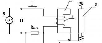
This method is widely used in the design of reed relays with a small number of contact groups. One or more reed switches are placed in the hollow core of the housing on which the winding is wound.
Design elements of the reed relay RES-24
An example of such use is current protection sensors in electrical networks supplying equipment. The coils are wound with wire thick enough to handle the current loads used in the manufacturing process. If the current exceeds, the magnetic field disconnects the reed switch contacts, and the equipment is de-energized. The setting is carried out by moving the reed switch along the threaded connection inside the coil along the axis.
Operating principle of a reed relay
The operation of a normally closed reed switch uses the principle of interaction of forces arising between magnetic bodies. In the electromagnetic field, impulses appear and are transmitted, electrons begin to move, causing movement and deformation of current-carrying contacts. Changing the position and state of the magnetic limit switch in a specific device or circuit leads to the opening of the contacts. Further changes in their position occur under the influence of other moving elements - buttons, end springs, disks, etc. Thus, the contacts are switched on and off alternately.
It will be interesting➡ Current relay: what is it and what is it used for?
This operating principle became the basis for the functioning of an intermediate reed relay that acts on a short circuit. Its design consists of two cores and a sealed durable glass cylinder filled with gas or a gas mixture. The cylinder itself is under constant action of electric current. The gases prevent the oxidation of the metal cores.
When a DC reed switch is connected to such a reed switch, a powerful magnetic field is formed around the cores. The presence of special gaps greatly facilitates the passage of this field between the parts of the relay. Next comes the emergence of an autonomous magnetic flux moving in a given direction. The joining of the cores is greatly accelerated by coating them with precious metals with lower resistance than conventional material. A constant magnetic flux is ensured by the design features of the reed relay.
The uniformity and integrity of parts is created through casting and stamping, and welding processes are used to connect them together. Therefore, the relay coil is magnetized to a minimum extent. A reed switch relay works according to this scheme, the principle of operation of which is quite simple. If the DC supply is interrupted, the contacts will open and the magnetic flux will disappear.
Related material: How to connect a capacitor
Advantages of reed switches
- Unlike conventional relays with electromagnetic coils and a core, reed switches do not have mechanical elements, a lever drive for moving the contacts and a steel core in the coil. Due to this, the design is smaller in size.
- Many indicators of reed relays are hundreds of times higher than conventional relays, insulation resistance, breakdown voltage, and, accordingly, electrical strength.
- Obviously, conventional relays cannot compare with reed switches in terms of speed. Switching frequency of contacts on reed switches is 1000Hz;
- The service life of reed switches is calculated in billions of switching cycles;
Characteristics of reed relays
A reed switch is a device consisting of two contacts made of a ferromagnetic alloy. They are placed in a special flask, which allows monitoring their work. When a permanent magnet approaches the contacts, a short circuit occurs to form a continuous circuit. For this reason, reed switches are known as limit switches.
All reed switches are marked according to the area of application. For example, the designation KEM refers to the switching of electrical mechanisms, the letter “A” means the ability to work in any climate, the letter “B” implies operation of the device only indoors. MKA is a magnetic switch for any climatic conditions.
The resistance of a standard switching track reed switch is approximately 0.2 Ohm. For a reed switch that operates to open, this indicator is at least 1 kOhm. These indicators can significantly speed up circuit switching. Magnetic switches of this type are used for power voltage circuits and have improved performance. Trip magnetic reed switches are used in many circuits, mainly for computer or security systems, control sensors and many other devices.
Typical errors when installing reed switches
- Installation of reed switches on moving elements of equipment, without taking into account vibration protection, as a result of which the glass bulb is destroyed.
- Installation of reed switches without taking into account the maximum permissible voltage and power values, as a result of which the contacts can stick, burn, and ultimately fail.
- When the reed switch moves linearly in space relative to the magnet, or vice versa, the distance interval must correspond to the strength of the magnetic field for switching contacts. At a large distance, the magnetic field may not be strong enough to trigger.
- Before connecting the installed network, check its operation with a multimeter in dialing mode. Especially when the structure is covered with a front panel or other elements, otherwise, to fix it, you will have to disassemble the installed elements.
- When installing current protection sensors on reed switches, do not forget to adjust them to the maximum operating current by rotating the core. Otherwise, they will operate at a lower current, limiting the production process, or they will not operate at all and the equipment will burn out.
FAQ
- To dampen vibration, they install reed switches containing mercury, is this not dangerous to health?
The mercury is in a sealed glass flask and in a durable shell, so it is not dangerous. It is prohibited to disassemble; if it fails, it must be disposed of in accordance with the established procedure in specialized organizations.
- Ultrasounds can affect the performance of reed switches?
Yes, indeed, ultrasound can significantly change the characteristics of the reed switch; the structure of the magnetic field can change, as a result of which its strength will not be enough to switch contacts. Therefore, when choosing a reed switch location, the influence of ultrasound should be avoided.
Types of models
High-quality reed relays are usually divided into several categories, which differ in the design of the contact group. Each variety has numerous positive characteristics that are highly valued by both specialists and home craftsmen. There are several types of reed switches on sale:
- With switching contact type.
- Traditional open-loop installations.
- Specific elements with closed contacts.
In addition to the main functional characteristics, experts also highlight technological parameters that divide sealed switching units into dry and mercury.