Rotor:
The moving part of an electric motor that rotates with the electric motor shaft, moving along with the magnetic field of the stator.
Stator:
Fixed component of an electric motor. It includes several windings whose polarity changes when alternating current (AC) passes through them. Thus, a combined stator magnetic field is created.
Rotation under the influence of a magnetic field
The advantage of magnetic fields created by current-carrying coils is the ability to swap the poles of a magnet by changing the direction of the current. It is this ability to change poles that is used to convert electrical energy into mechanical energy.
Like poles of magnets repel each other, opposite poles attract. This property can be said to be used to create continuous rotor motion by constantly changing the polarity of the stator. The rotor here is a magnet that can rotate.
Pole rotation using alternating current
Pole rotation using alternating current
The polarity is constantly reversed using alternating current (AC). Next we will see how the rotor is replaced by a magnet, which rotates under the influence of induction. Alternating current plays an important role here, so it will be useful to provide some brief information about it here:
Alternating current - AC
Alternating current is understood as an electric current that periodically changes its direction in a circuit so that the average value of the current over the period is zero. A rotating magnetic field can be created using three-phase power. This means that the stator is connected to a three-phase AC source. A complete cycle is defined as a 360 degree cycle. This means that each phase is located at an angle of 120 degrees relative to the other. The phases are depicted as sinusoidal curves, as shown in the figure.
Three-phase alternating current
Three-phase power is a continuous series of overlapping alternating current (AC) voltages.
Pole reversal
The following pages explain how the rotor and stator interact to make the motor rotate.
For clarity, we replaced the rotor with a rotating magnet and the stator with coils. On the right side of the page is an image of a two-pole three-phase electric motor. The phases are connected in pairs: the 1st phase corresponds to coils A1 and A2, the 2nd phase - B1 and B2, and the 3rd phase corresponds to C1 and C2. When current is applied to the stator coils, one of them becomes the north pole, the other becomes the south pole. Thus, if A1 is the north pole, then A2 is the south pole.
AC Power
The windings of phases A, B and C are located at an angle of 120 degrees relative to each other.
The number of poles of the electric motor is determined by the number of intersections of the winding field with the rotor field. In this case, each winding is crossed twice, which means that we have a two-pole stator. Thus, if each winding appeared four times, it would be a four-pole stator, etc.
When electric current is applied to the phase windings, the motor shaft begins to rotate at a speed determined by the number of poles (the fewer poles, the lower the speed)
Rotor rotation
The following describes the physical principle of operation of an electric motor (how the rotor rotates inside the stator). For clarity, let's replace the rotor with a magnet. All changes in the magnetic field occur very quickly, so we need to break the whole process into stages. When three-phase alternating current passes through the stator windings, a magnetic field is created in it, resulting in mechanical forces that cause the rotor to rotate in the direction of rotation of the magnetic field.
Once it starts rotating, the magnet will follow the changing magnetic field of the stator. The stator field is changed so as to maintain rotation in one direction.
Classification of electric motors
Today, industrial and household appliances use several types of electric motors, which belong to several classes of equipment. In turn, motors are classified according to several criteria, the main of which is the type of supply voltage. Depending on the supply voltage, electric motors are divided into three types:
- direct current;
- alternating current;
- universal electric motors operating on both direct and alternating current.
Each of these types has several design implementations that divide a large group of electric motors into several subgroups according to the design features of the system for exciting electromagnetic fields and controlling the operation of the motor.
DC motors, in turn, are divided into two subgroups:
- brushed motors with different options for connecting the excitation windings of electromagnetic fields in the rotor and stator, as well as with permanent magnets;
- brushless DC electric motors with an electronic control system that generates a rotating electric field of a given frequency.
The scope of application of DC motors is determined by their features and the following advantages:
- high efficiency;
- high torque regardless of rotation speed;
- compact dimensions compared to AC electric motors of equal power;
- simple control system for the frequency and direction of shaft rotation;
- the ability to operate in generator mode in systems of regenerative return of electricity to the supply network in braking mode.
Thanks to these advantages and features, the DC motor has become widely used to solve various problems related to:
- drive of various types of electric vehicles;
- use in crane systems;
- use as servo drives for various purposes;
- use in miniature devices for household and special purposes. As a rule, electric motors with permanent magnets are used for these purposes.
Read here! Characteristics of electric motors: main parameters and explanation of the markings of modern electric motors
The most widespread in technology are engines with a commutator and brushes located on the rotor, which determine several main disadvantages of this type of engine:
- the need for periodic maintenance;
- significant noise generated during operation;
- possibility of sparks and unpleasant odors.
Depending on the method of connecting the rotor and stator windings in brushed DC motors, four types of winding switching are distinguished, each of which has its own advantages, disadvantages and area of optimal use. These include:
- connection with serial excitation of an electromagnetic field;
- connection with parallel excitation;
- switching with biased excitation;
- the use of an electric motor with permanent magnets, usually on the motor stator.
Induction
Previously, we established how an ordinary magnet rotates in a stator. AC motors have rotors rather than magnets. Our model is very similar to a real rotor, except that the rotor is polarized under the influence of a magnetic field. This is caused by magnetic induction, due to which an electric current is induced in the rotor conductors.
Induction
Basically the rotor works the same way as a magnet. When the electric motor is turned on, current flows through the stator winding and creates an electromagnetic field that rotates in a direction perpendicular to the rotor windings. Thus, a current is induced in the rotor windings, which then creates an electromagnetic field around the rotor and rotor polarization.
In the previous section, to make it easier to explain the principle of operation of the rotor, replacing it with a magnet for clarity. Now let's replace the stator with a magnet. Induction is a phenomenon that occurs when a conductor moves in a magnetic field. The relative movement of a conductor in a magnetic field leads to the appearance of a so-called induced electric current in the conductor. This induced current creates a magnetic field around each rotor conductor winding. Since three-phase AC power causes the stator's magnetic field to rotate, the induced magnetic field of the rotor will follow this rotation. This way the motor shaft will rotate. AC motors are often called AC induction motors, or AC induction motors.
Design and principle of operation
The main driving force of any electric motor is electromagnetic induction.
Electromagnetic induction, to describe it in a nutshell, is the appearance of current in a conductor placed in an alternating magnetic field. The source of the alternating magnetic field is a stationary motor housing with windings placed on it - a stator connected to an alternating current source. It contains a moving element - a rotor, in which current arises. According to Ampere's law, an electromotive force - EMF - begins to act on a charged conductor placed in a magnetic field, which rotates the rotor shaft. Thus, the electrical energy supplied to the stator is converted into mechanical energy by the rotor. Various mechanisms that perform useful work can be connected to the rotating shaft. AC electric motors are divided into synchronous and asynchronous. The difference between them is that in the first, the rotor and the magnetic field of the stator rotate at the same speed, and in the second, the rotor rotates more slowly than the magnetic field. They differ both in structure and principle of operation.
Asynchronous motor
Asynchronous motor device
Windings are attached to the stator of an asynchronous motor, creating an alternating rotating magnetic field, the ends of which are brought out to the terminal box. Since the engine heats up during operation, a cooling fan is installed on its shaft.
The rotor of an asynchronous motor is made with the shaft as a single unit. It consists of metal rods closed to each other on both sides, which is why such a rotor is also called a squirrel-cage rotor. In appearance, it resembles a cage, which is why it is often called a “squirrel wheel”. The slower rotation of the rotor compared to the rotation of the magnetic field is the result of power loss due to friction of the bearings. By the way, if there had not been this difference in speed, the EMF would not have arisen, and without it there would have been no current in the rotor and no rotation itself.
The magnetic field rotates due to the constant change of poles. In this case, the direction of the current in the windings changes accordingly. The rotation speed of an asynchronous motor shaft depends on the number of poles of the magnetic field.
Synchronous motor
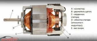
Synchronous motor device
The design of a synchronous electric motor is slightly different. As the name suggests, in this motor the rotor rotates at the same speed as the magnetic field. It consists of a housing with windings attached to it and a rotor or armature equipped with the same windings. The ends of the windings are brought out and fixed to the collector. Voltage is applied to the commutator or slip ring via graphite brushes. In this case, the ends of the windings are placed in such a way that voltage can be applied to only one pair at a time.
Unlike asynchronous motors, voltage is supplied to the rotor of synchronous motors by brushes, charging its windings, and is not induced by an alternating magnetic field. The direction of the current in the rotor windings changes in parallel with the change in the direction of the magnetic field, so the output shaft always rotates in one direction. Synchronous electric motors allow you to regulate the speed of rotation of the shaft by changing the voltage value. In practice, rheostats are usually used for this.
Operating principle of electric motors
Induction motors consist of a rotor and a stator.
The currents in the stator windings are created by the phase voltage, which drives the induction motor. These currents create a rotating magnetic field, also called a stator field. The rotating magnetic field of the stator is determined by the currents in the windings and the number of phase windings.
A rotating magnetic field forms a magnetic flux. The rotating magnetic field is proportional to the electric voltage, and the magnetic flux is proportional to the electric current.
The rotating magnetic field of the stator moves faster than the rotor, which promotes the induction of currents in the windings of the rotor conductors, resulting in the formation of a rotor magnetic field. The magnetic fields of the stator and rotor form their own fluxes, these fluxes will attract each other and create a torque that causes the rotor to rotate. The operating principles of an induction motor are shown in the illustrations on the right.
Thus, the rotor and stator are the most important components of an AC induction motor. They are designed using CAD (Computer Aided Design). Next we will talk in more detail about the design of the rotor and stator.
How do electric motors work?
Asynchronous motors
We briefly described the external differences of electric motors, now a few words about the design and operation. Asynchronous motors use a stator to create a rotating magnetic field along the axis. The squirrel cage drum is rarely, if ever, made from ferromagnetic materials. Otherwise, the heating would be significant. In fact, it turns out to be an induction furnace.
The silumin drum contains copper conductors along the magnetic field lines. The difference in conductivity is such that no insulation is carried out: the red-brown wires carry the current. The field induced by the stator emf is weak. Special measures are used to help accelerate the shaft. The magnetic field of the rotor does not adhere well, the asynchronous motor stands still. An effective countermeasure to the problem is limited to the creation of a double squirrel cage: a second row of copper wires runs along the drum at a certain depth. United at the ends by a single network.
At startup, the current frequency and field penetration depth are high. Both layers of the squirrel cage are included in the work. As you accelerate, the difference levels out and drops to zero. The amplitude of the field decreases, the outer layer of the squirrel cage remains working. Please note that the rotor is powerless to catch up with the field; it slips and lags. Therefore, the motors are called asynchronous. The British make it simpler - they call it induction.
If the field is rotated at the rotor speed, the emf ceases to be induced. A deceleration will follow, and the cycle will repeat, starting with acceleration. The rotor will still lag behind the field. This is how a short-circuit type device works. A phase rotor (thanks Wikipedia), containing a three-phase winding, performs several functions, according to the purpose of the device:
- It is fed with electricity through the current collector ring. Now the rotor receives phase and induces an emf on the stator. Gradually the shaft is picked up by the field, the further process is described above.
- Powered by direct current. A synchronous motor is formed.
- It is equipped with rheostats and chokes that regulate speed.
- Implements inverter control (complicated first case).
The operating principle of asynchronous motors: an induced EMF is used, the rotation speed is unable to catch up with the field (currents disappear). Otherwise, the motor type changes (synchronous). To regulate speed, the amplitude of the supply voltage is often used. The method is suitable for asynchronous motors with a squirrel-cage wound rotor. Let's list the methods:
AC Motor Operation
- Suitable for machines with squirrel-cage rotors:
- Regulation of supply voltage frequency.
- Changing the number of stator pole pairs. As a result, the speed of rotation of the field changes, giving the desired effect.
- For machines with a wound rotor it is allowed:
- Insert a rheostat into the power circuit. Sliding losses increase, naturally changing the speed.
- Use special valves. The sliding energy is rectified by a Larionov circuit and supplied in the form of a direct voltage to an auxiliary electric motor, which cuts pulses through externally controlled thyristors. Power that would normally be lost is returned. Through the shaft of the auxiliary motor, a transformer, the windings of which are partially connected to the power supply network. Speed control is performed by introducing additional EMF. This is done either directly (via the power source) or by shifting the switching angle of the thyristors relative to the power supply. The frequency deviates from the nominal value.
- A dual-fed motor is an option for implementing speed control in wound-rotor equipment. The type is more often used to implement generator circuits. The rotor floats with rotation speed - the motor is still asynchronous. The stator and rotor are powered separately. Allows you to set the frequency for each winding, which naturally leads to the desired speed changes.
For asynchronous motors, changing the amplitude of the supply is suitable. The most expensive valve circuits have the highest efficiency.
Asynchronous motor
Motor stator
The stator is the stationary electrical component of an electric motor. It includes several windings, the polarity of which constantly changes as alternating current (AC) passes through them. Thus, a combined stator magnetic field is created.
All stators are installed in a frame or housing. The stator housing of Grundfos electric motors for electric motors up to 22 kW is most often made of aluminum, and for electric motors with higher power - from cast iron. The stator itself is installed in the stator housing. It consists of thin plates of electrical steel wrapped in insulated wire. The core consists of hundreds of such plates. When power is applied, alternating current passes through the windings, creating an electromagnetic field perpendicular to the rotor conductors. Alternating current (AC) causes the magnetic field to rotate.
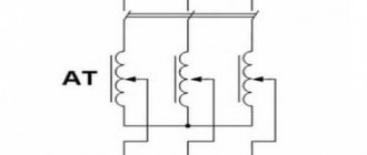
The stator insulation must comply with the requirements of IEC 62114, which provides different protection classes (temperature levels) and temperature change (AT). Grundfos electric motors have protection class F, and when the temperature increases, class B. Grundfos produces 2-pole motors with power up to 11 kW and 4-pole motors with power up to 5.5 kW. Grundfos purchases more powerful electric motors from other companies whose product quality meets Grundfos standards. For pumps, stators with two, four and six poles are mainly used, since the speed of the electric motor shaft determines the pressure and flow of the pump. The stator can be manufactured to handle different voltages, frequencies and output powers, as well as a variable number of poles.
Links
Wikimedia Foundation. 2010.
See what “AC electric motor” is in other dictionaries:
AC motor
– – [A.S. Goldberg. English-Russian energy dictionary. 2006] Topics: energy in general EN ac motor ...
Rice. 1 The design of the simplest commutator DC motor with a two-pole stator and a two-pole rotor. DC motor is an electric machine, ma ... Wikipedia
An alternating current machine designed to operate in motor mode (see Alternating current machine). P. t. e. divided into synchronous and asynchronous. Synchronous electric motors (See Synchronous electric motor) are used in... ...
An electrical machine used to produce alternating current (generator) or to convert electrical energy into mechanical energy (motor) or into electrical energy of another voltage or frequency (converter) P. t. m.... ... Great Soviet Encyclopedia
AC machine current, intended for operation in engine mode. P. t. e. divided into synchronous and asynchronous. Synchronous electric motors are used in electric drives mainly. when constant angular velocity is required. From asynchronous... ... Big Encyclopedic Polytechnic Dictionary
AC electric drive
– direct [alternating] current electric drive An electric drive containing a direct [alternating] current electric motor. [GOST R 50369 92] Topics: electric drive EN ac drivealternating current drive DE Wechselstromantrieb ... Technical Translator's Guide
DC (AC) electric drive
– 3.1.3 direct (alternating) current electric drive: A drive containing a direct (alternating) current electric motor and a gearbox;
The phenomenon of electromagnetic induction became the basis for the emergence and development of all electrical machines. The discoverer of this phenomenon at the end of the 19th century was Michael Faraday, an English scientist and experimenter. He conducted experiments with the first electric machines. Now it is impossible to imagine our life without them. Electric motors have become one of the most common electrical machines.
To operate an electric motor, voltage is required, the properties of which determine its design. The following electric motors operate on alternating voltage and current:
operate at constant voltage and current:
- collector;
- unipolar;
- stepper.
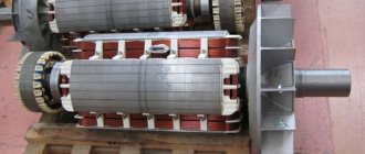
Motor rotor
Electric motors use so-called “squirrel wheels” (squirrel-cage rotors), the design of which resembles squirrel drums.
When the stator rotates, the magnetic field moves perpendicular to the windings of the rotor conductors; current appears. This current circulates through the windings of the conductors and creates magnetic fields around each rotor conductor. Since the magnetic field in the stator is constantly changing, the field in the rotor also changes. This interaction causes the rotor to move. Like the stator, the rotor is made of electrical steel plates. But, unlike the stator, with windings made of copper wire, the rotor windings are made of cast aluminum or silumin, which act as conductors.
Principle of operation
The operation of an asynchronous motor is based on the property of a three-phase current, capable of creating a rotating magnetic field in the stator windings. In the electric motors under consideration, the synchronous rotation frequency of the electromagnetic field is directly proportional to the natural frequency of the alternating current.
There is an inversely proportional dependence of the rotation speed on the number of pole pairs in the stator windings. Considering that the phase shift is 60º, the dependence of the rotor speed (in rpm) can be expressed by the formula:
As a result of the action of magnetic induction on the rotor core, an emf will arise in it, which, in turn, causes the appearance of an electric current in a closed conductor. An Ampere force will arise, under the influence of which the closed loop will begin to rotate in pursuit of the magnetic field. In the nominal operating mode, the rotor rotation speed is slightly behind the rotation speed of the magnetic field created in the stator. When the frequencies coincide, the magnetic flux stops, the current disappears in the rotor windings, as a result of which the force ceases. As soon as the shaft rotation speed lags behind, the action of the ampere force is resumed by alternating currents of magnetic fields.
The difference in the rotation frequencies of the magnetic fields is called the slip frequency: ns=n1–n2, and the relative value s, which characterizes the lag, is called slip.
s = 100% * (ns/ n1) = 100% * (n1 - n2) / n1, where ns is the slip frequency; n1, n2 – rotation frequencies of stator and rotor magnetic fields, respectively.
In order to reduce the harmonics of the EMF and smooth out the pulsations of the moment of force, the rods of the short-circuited turns are slightly beveled. Take another look at Fig. 2 and pay attention to the location of the rods that act as rotor windings relative to the axis of rotation.
Slip depends on the mechanical load applied to the motor shaft. In asynchronous electric motors, the sliding parameters change in the range from 0 to 1. Moreover, in idle mode, the rotor that has gained speed experiences almost no active resistance. S approaches zero.
An increase in load contributes to an increase in slip, which can reach unity when the engine stops due to overload. This condition is equivalent to a short circuit and can damage the device.
The relative value of the lag corresponding to the rated load of the electrical machine is called the rated slip. For low-power electric motors and medium-power engines, this figure varies within small limits - from 8% to 2%. When the electric motor rotor is stationary, the slip tends to 0, and when idling it approaches 100%.
When starting an electric motor, its windings are under load, which leads to a sharp increase in starting currents. When the rated power is reached, electric motors with squirrel-cage turns independently restore the rated rotor frequency.
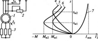
Pay attention to the sliding torque curve shown in Fig. 3.
Rice. 3. Sliding torque curve
As the torque increases, the coefficient s changes from 1 to 0 (see the segment “motor region”). The shaft rotation speed also increases. If the shaft rotation speed exceeds the rated frequency, the torque will become negative and the engine will go into generation mode (the “generating region” segment). In this mode, the rotor will experience magnetic resistance, which will lead to braking of the motor. The oscillatory process will be repeated until the torque stabilizes and the slip approaches the nominal value.
Asynchronous electric motors
In previous sections, we discussed why AC motors are also called induction motors, or squirrel wheel motors. Next, we will explain why they are also called asynchronous electric motors. In this case, the relationship between the number of poles and the number of revolutions made by the rotor of the electric motor is taken into account.
The rotation frequency of the magnetic field is generally considered to be the synchronous rotation frequency (Ns). The synchronous speed can be calculated as follows: line frequency (F) multiplied by 120 and divided by the number of poles (P).
If, for example, the mains frequency is 50 Hz, then the synchronous speed for a 2-pole electric motor is 3000 rpm.
The synchronous speed decreases as the number of poles increases.
The table below shows the synchronous speed for different numbers of poles. Synchronous speed for different number of poles
| Number of poles | Synchronous speed 50 Hz | Synchronous speed 60 Hz |
| 2 | 3000 | 3600 |
| 4 | 1500 | 1800 |
| 6 | 1000 | 1200 |
| 8 | 750 | 900 |
| 12 | 500 | 600 |
Connection diagram of the electric motor to the network
AC motors are available in three and single phase types. Asynchronous single-phase motors have 2 outputs on the body and connecting them to the network is not difficult. Because The entire household electrical network is mainly single-phase 220V and has 2 wires - phase and zero. With synchronous ones everything is much more interesting, they can also be connected using 2 wires, just connect the rotor and stator windings. But they need to be connected so that the single-pole magnetization windings of the rotor and stator are located opposite each other. Motors for 3-phase networks present difficulties. Well, firstly, such motors generally have 6 terminals in the terminal box, and this means that the motor windings need to be connected yourself, and secondly, their windings can be connected in different ways - “star” and “delta” type. Below is a diagram of the terminal connections in the terminal box, depending on the type of winding connection.
Connecting the same electric motor in different ways to the same electrical network will result in different power consumption. In this case, incorrect connection of the electric motor can lead to melting of the stator windings.
Typically, asynchronous motors are designed to be connected to a three-phase network at two different voltages that differ by a factor of two. For example, the motor is designed to be connected to a network with a voltage of 380/660 V. If the network has a linear voltage of 660 V, then the stator winding should be connected with a star, and if 380 V, then with a triangle. In both cases, the voltage on the winding of each phase will be 380 V. The terminals of the phase windings are placed on the panel in such a way that it is convenient to connect the phase windings using jumpers, without crossing the latter. Some small motors have only three terminals in the terminal box. In this case, the motor can be connected to the network at one voltage (the stator winding of such a motor is connected with a star or triangle inside the motor).
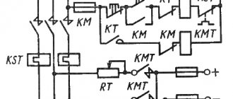
A schematic diagram of connecting an asynchronous motor with a wound rotor to a three-phase network is shown in the figure. The rotor winding of this motor is connected to a starting rheostat YAR, which creates an additional resistance Radd in the rotor circuit.
Motor slip
Now we already know that AC electric motors are called asynchronous because the moving field of the rotor lags behind the field of the stator.
In AC motors, torque results from the interaction between the rotor and the rotating magnetic field of the stator. The magnetic field of the rotor windings will tend to approach the magnetic field of the stator, as described earlier. During operation, the rotor speed is always lower than the speed of the stator magnetic field. Thus, the rotor magnetic field can cross the stator magnetic field and create torque. This difference in the rotational speed of the rotor and stator fields is called slip and is measured in %. Sliding is necessary to create torque. The greater the load, and therefore the torque, the greater the slip.
Types of engines and their design
AC electric motors have a different design, thanks to which it is possible to create machines with the same rotor speed relative to the stator magnetic field, and machines where the rotor “lags behind” the rotating field. According to this principle, these motors are divided into corresponding types: synchronous and asynchronous.
Asynchronous
The design of an asynchronous electric motor is based on a couple of important functional parts:
- The stator is a cylindrical block made of steel sheets with grooves for laying conductive windings, the axes of which are located at an angle of 120˚ relative to each other. The poles of the windings go to the terminal box, where they are connected in different ways, depending on the required operating parameters of the electric motor.
- Rotor. In the design of asynchronous electric motors, two types of rotors are used:
- Short-circuited. So called because it is made from several aluminum or copper rods short-circuited using end rings. This design, which is a current-carrying rotor winding, is called a “squirrel cage” in electromechanics.
- Phase. On rotors of this type, a three-phase winding is installed, similar to the stator winding. Most often, the ends of its conductors go to the terminal pad, where they are connected in a star, and the free ends are connected to slip rings. The phase rotor allows you to use brushes to add an additional resistor to the winding circuit, which allows you to change the resistance to reduce inrush currents.
In addition to the described key elements of an asynchronous electric motor, its design also includes a fan for cooling the windings, a terminal box and a shaft that transmits the generated rotation to the working mechanisms of the equipment whose operation is provided by this motor.
The operation of asynchronous electric motors is based on the law of electromagnetic induction, which states that electromotive force can only arise under conditions of a difference in the speed of rotation of the rotor and the magnetic field of the stator. Thus, if these speeds were equal, the EMF could not appear, but the influence on the shaft of such “braking” factors as load and bearing friction always creates conditions sufficient for operation.
Synchronous
The design of synchronous AC electric motors is somewhat different from the design of asynchronous analogues. In these machines, the rotor rotates around its axis at a speed equal to the rotation speed of the stator's magnetic field. The rotor or armature of these devices is also equipped with windings, which are connected at one end to each other and at the other to a rotating collector. The contact pads on the commutator are mounted in such a way that at a certain point in time it is possible to supply power through the graphite brushes to only two opposite contacts.
Operating principle of synchronous electric motors:
- When the magnetic flux in the stator winding interacts with the rotor current, a torque arises.
- The direction of movement of the magnetic flux changes simultaneously with the direction of the alternating current, due to which the rotation of the output shaft is maintained in one direction.
- The desired rotation speed is adjusted by adjusting the input voltage. Most often, in high-speed equipment, such as rotary hammers and vacuum cleaners, this function is performed by a rheostat.
The most common reasons for failure of synchronous electric motors are:
- wear of the graphite brushes or weakening of the pressure spring;
- wear of shaft bearings;
- collector contamination (clean with sandpaper or alcohol).
Three Phase Alternator
How the device works
The parts of an asynchronous motor are a stator and a rotor.
If you start applying electric current to the stator cables, the motor will start running. Induction begins inside the machine, that is, a powerful electromagnetic field is induced in the engine. For example, in technology with constant electric current it is necessary to create an electromagnetic field in the armature using brushes.
According to Faraday's law, an induced electric current passes through a device that has a short-circuited winding because the circuit is closed using the short circuit method. This current, like the voltage in the stator, leads to the appearance of a magnetic field. The rotor of the device becomes a magnet in the stator, which has a rotating electromagnetic field.
The stator does not move and the field moves inside the machine at normal speed and an electric current is induced in the rotor, making it a powerful magnet. Thanks to this, the movable rotor begins to move due to the stator field. Why asynchronous rotation occurs can be understood by knowing that at the moment of unification, the magnetic fields try to compensate for each other’s shortcomings.
The sliding process can take place not only with a slight delay, but also with an advance. In the first case, the motor converts electrical energy into mechanical energy (for example, the machine begins to move). And in the second, generator work occurs, that is, the movement of the device parts generates electricity.
The torsional torque generated is entirely dependent on the DC voltage power to energize the stator. By constantly changing the frequency of the electric current and the voltage, a person can control the torque, which allows him to influence the operating mode of the engine. This idea works both on simple single-phase motors and on three-phase motors.