Application and design of commutator electric motors
The design of a commutator electric motor The distinctive features of commutator motors include: high armature rotation speed, small overall dimensions and weight. Used in vacuum cleaners, kitchen machines, hand-held power tools. For these machines, as a rule, universal (built-in) commutator electric motors are used. It is customary to call universal motors commutator motors that operate on both alternating and direct current.
An AC commutator motor is structurally more complex than a DC motor. These complications are associated with the need to assemble the inductor core from separate sheets, as well as laying an additional winding that compensates for the phenomena associated with sparking under the brushes. It is impossible not to note such disadvantages of these machines as high noise levels, interference with radio reception, and abrasion of carbon brushes. At the same time, in some respects they are superior to asynchronous motors. These include: a high maximum rotation speed (up to 25,000 rpm), the possibility of its smooth adjustment, and the availability of good starting data.
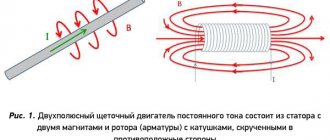
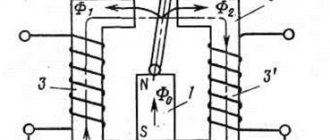
In order to understand how a commutator electric motor works, its operating principle can be illustrated using the following simple experiment (Fig. 1). If you pass current through a rectangular frame placed between the poles of a magnet (permanent or electromagnet), it begins to rotate. Using half-ring contacts, the current in the frame is switched, which ensures its continuous rotation in one direction. Commutator motors contain many such frames, and a corresponding number of pairs of contacts. Thus, the operation of motors of this type is ensured by the interaction of magnetic fields present in the stator and armature.
In Fig. Figure 2 shows a diagram explaining the connection of commutator electric motors. The entire power load is carried out by a triac that supplies voltage to the motor and is connected in series to it.
Single-phase commutator electric motors have a high power density. They are quite widely and successfully equipped with household appliances and hand-held power tools. Commutator single-phase electric motors are installed on the vast majority of household electrical appliances. The connection to the DC network is carried out using the entire field winding. Only part of it is used to connect to the variable network. This eliminates the need to turn on compensation windings.
The original article is posted on our website cable.ru
.
If this material was useful to you, please share
them on social networks!
And in order not to miss the release of new articles, click “Like”
and
subscribe
to our channel:
Kabel.RF: all about electrics
.
Source
Description of the commutator motor
First, before considering installation options, let’s clarify what the concept of a commutator motor means. An electric motor is a device that converts electrics into mechanics and vice versa. If the motor winding has a connecting link with the collector unit and takes part in the transformation of energy, then such a unit is called a collector unit.
Jacobi B.S. (1801-1874) inventor of the first commutator engine in 1837.
Electric motor components:
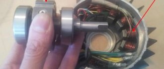
- The rotor, a part of the motor, is subject to rotation;
- The stator, a part of the motor, remains in a stationary position;
- An inductor, a piece of an aggregate that, in order to generate a torque, participates in the formation of a magnetic field flow. The inductor consists of: magnets, a set of turns. The mechanism is made as part of a rotor or a fixed part;
- An anchor, a unit that supports the movement of the load, ordered movement of particles, electric charge carriers and, due to induction, generates an electromotive force. The armature function is performed by either the rotor or the stator;
- Brushes, a part that is part of the electrical circuit through which current is transmitted to the armature. The material from which brushes are made is usually graphite. The motor contains at least two brushes for the “positive” and “negative” poles;
- The commutator is the part of the unit that is in contact with the brushes and distributes the current.
The name of the unit comes from the name of the electric motor rotor assembly - the commutator. Visually, the collector is a part in the form of a cylinder, which consists of copper plates isolated from each other.
Important! Experienced users know that to increase the service life of a new installation, break in the commutator motor. To do this, the unit operates at 15-20% power without load for 10-15 minutes. This will avoid burning out the collector and will give a power increase of 10-15%.
Universal commutator motor.
Read also: Chipper for woodchips production
Operation of an AC commutator motor
In household appliances, hand-held power tools, automotive electrical equipment and automation systems, a commutator AC motor is often used, the connection diagram of which, as well as the device, are similar to DC motors.
Their widespread use is explained by their compactness, low weight, low cost and ease of operation. In this segment, motors with high frequency and low power are most in demand.
Commutator motor design - alternating current
A general idea of the structure of an AC commutator motor can be clearly obtained from this schematic representation in Fig. 1.
Typical malfunctions of this type of electric motors include the following reasons:
and bearing wear.
The AC commutator motors that we all know - from vacuum cleaner photo 1 and other household appliances with such motors - are subject to:
and thermal overloads, and in some cases parts must be repaired or completely replaced.
Operating principle and design features
This device is quite specific, having, due to its similarity with DC machines, similar characteristics and inherent advantages.
The difference from DC motors is the material of the stator housing, made of sheets of electrical steel, due to which it is possible to reduce eddy current losses.
So that the engine can operate from a regular network, i.e. 220 V, field windings are connected in series.
These motors, called universal due to the fact that they operate on alternating and direct current, are single- and three-phase.
Video: Universal brushed motor
Design features and principle of operation
In fact, a commutator motor is a rather specific device that has all the advantages of a DC machine and, therefore, has similar characteristics.
The difference between these motors is that the stator housing of the AC motor is made from separate sheets of electrical steel to reduce eddy current losses. The excitation windings of the machine are connected in series to optimize operation in a 220V household network. They can be either single- or three-phase; due to the ability to operate on direct and alternating current, they are also called universal. In addition to the stator and rotor, the design includes a brush-commutator mechanism and a tachogenerator. The rotation of the rotor in a commutator motor occurs as a result of the interaction of the armature current and the magnetic flux of the field winding. Through the brushes, current is supplied to a commutator assembled from trapezoidal plates and is one of the rotor units connected in series to the stator windings.
In general, the principle of operation of a commutator motor can be clearly demonstrated using the experiment known from school with the rotation of a frame placed between the poles of a magnetic field. If current flows through the frame, it begins to rotate under the influence of dynamic forces. The direction of movement of the frame does not change when the direction of current movement in it changes.
Connecting the field windings in series gives a large maximum torque, but high idle speeds appear, which can lead to premature failure of the mechanism.
Connection diagram (simplified)
A typical connection diagram provides for the output of up to ten contacts to the contact strip. The current L flowing through one of the brushes enters the commutator and armature, then passes to the stator windings through the second brush and jumper, leaving the neutral N.
This method of connection does not provide for reversing the motor, since connecting the windings in parallel leads to a simultaneous change in the poles of the magnetic fields. As a result, the direction of the moment is always the same.
We recommend:
It is possible to change the direction of rotation if you change the locations of the winding outputs on the contact strip. The motor is turned on directly when the rotor and stator outputs are connected to a brush-commutator mechanism. To turn on the second speed, the terminals of half the winding are used. We must not forget that from the moment of such connection the motor operates at maximum power, so its operation time cannot exceed 15 seconds.
Video: Connecting and adjusting engine speed from a washing machine
Engine control
In practice, various methods of regulating engine operation are used. This can be an electronic circuit where the regulating element is a triac, which “passes” a given voltage to the motor. It works like an instantaneous key, opening when a control impulse is received at its gate.
The principle of operation implemented in circuits with a triac is based on full-wave phase control, where the voltage supplied to the motor is tied to the pulses that arrive at the electrode. In this case, the frequency with which the armature rotates is directly proportional to the voltage supplied to the windings.
Simplified, this principle can be described by the following points:
- a signal from an electronic circuit is supplied to the triac gate;
- the gate opens, current flows through the stator windings, causing the motor armature M to rotate;
- instantaneous rotation speed values are converted by the tachogenerator into electrical signals, forming feedback with control pulses;
- as a result, the rotation of the rotor remains uniform under any load;
- Using relays R and R1, the motor is reversed.
Another circuit is a phase-pulse thyristoran.
How to check the armature of a commutator motor
There are three methods for such verification. I check them sequentially.
Method one: measuring the resistance between adjacent lamellas
In the photo you see the determination of the resistance between the collector plates in exactly this way.
I place the multimeter probes on adjacent lamellas. I marked the place of the first check with a marker, and moved from it sequentially in a circle, checking the collector plates one after another. With this method you need to have a lot of patience, I tell you.
Due to my ignorance, I made a mistake that I want to warn you against. When checking, it is necessary to remove the brushes from the brush holder, as they create additional connections in electrical circuits that distort the real picture. The measurement data turns out to be unreliable.
You should carefully monitor the readings of the multimeter; they were all the same for me: the accuracy class of the ohmmeter is quite high.
When it is insufficient, it will be difficult to operate the device, since the resistance of these parts is small. In this case, a different technique is used.
Method two: measuring the resistance of diametrically opposed lamellas
What I told you about patience was just flowers. This is where the eightieth level of care and precision is required.
The ohmmeter probes must be placed not on adjacent lamellas, but on diametrically opposite ones, that is, on those places that are connected by brushes on the engine. I also marked them with a marker.
Method three: measuring the voltage drop with a voltmeter
I assembled the following circuit:
· 12 V battery;
· increased power resistance of 20 ohms;
· multimeter with probes;
Here I want to make a small digression and explain that the accuracy of the measurement increases the stabilization of the current source due to:
· large battery capacity, which creates a constant voltage level during short-term testing;
· increased resistor power, which prevents it from heating up and maintains the accuracy of the parameters at a current of less than 1 A;
· low-impedance connecting wires.
I ran the first connecting wire directly from the battery terminal to the collector plate. In the second I inserted a current-limiting resistor, which limited the high current. I installed a voltmeter in parallel with the collector plates. It turned out like this.
Then I sequentially placed probes on pairs of collector lamellas and took voltmeter readings. The battery, through a resistor and connecting wires, produces the same voltage for the duration of the measurement. Therefore, the voltmeter readings according to Ohm's law depend only on the circuit resistance.
The same method allows you to measure the current through the collector plates with a milliammeter and compare it.
My resistance measurements turned out to be the same in all three cases. I concluded that there are no defects in my armature electrical circuit. Oof! The screwdriver is ready for baptism of fire!
What about my new multimeter? He may have his shortcomings, but he coped with the task.
The final conclusion about the serviceability of the commutator motor can be made after checking its stator.
The article was written for you by Elena Rogozhnikova. You can contact her at the following addresses:
Source
Machine advantages and disadvantages
The advantages include:
- small sizes;
- versatility, i.e. work on constant and alternating voltage;
- high starting torque;
- independence from network frequency;
- speed;
- soft adjustment of rotation speed over a wide range when varying the supply voltage.
Disadvantages are also associated with the use of a brush-collector junction, which entails:
- reducing the service life of the mechanism;
- sparks occurring between the brushes and the commutator;
- high noise level;
- a large number of collector elements.
Basic faults
The sparking that occurs between the brushes and the commutator is the most important issue that requires attention. To avoid more serious malfunctions, such as peeling and deformation of the lamellas or overheating of the lamellas, a worn-out brush must be replaced.
In addition, a short circuit between the armature and stator windings is possible, causing strong sparking at the commutator-brush junction or a significant drop in the magnetic field.
To extend the service life of the engine, two conditions must be met - a professional manufacturer and a competent user, i.e. strict adherence to operating hours.
Video: Brushed electric motor
Source
Field winding options
There are several ways to connect a brushed DC motor. The excitation of the motor depends on the method of connecting the windings.
- Independent connection. The DC motor windings are connected separately. Two DC sources are used for connection. The stator winding is equipped with a rheostat. It is necessary to set the required rotor speed. The rotor winding is equipped with a starting rheostat. It is needed to control the current strength in the rotor winding when starting the power plant;
- Parallel connection. The armature and stator windings are powered from the same power source. The windings are equipped with regulators;
- Series-connected. An electric motor of this design has a stator winding connected in series with the armature winding. The rotor may be equipped with a regulator necessary to limit the starting current. The stator is equipped with a rheostat that regulates the shaft rotation speed.
IMPORTANT: Using a commutator motor with a serial connection without a load can lead to its failure.
- Mixed excitement. This design uses two coils connected in parallel and in series at the same time.
How does a commutator motor with a brush mechanism work in household appliances?
A vacuum cleaner, coffee grinder, drill, hammer drill, trimmer is not a complete list of equipment that uses the conversion of electrical energy into mechanical energy to operate household devices.
They contain complex technical components and require skillful handling, periodic inspection, and proper maintenance. When handled carelessly, various breakdowns occur.
The material in the article provides advice to a home craftsman working with electric tools or planning to independently repair an electric motor with a brush mechanism and commutator. The text is visually supplemented with diagrams, pictures and videos.
The information provided is collected in order to draw the attention of users to the rules for operating household appliances with a commutator motor. It will help you consciously identify emerging defects in a working circuit and promptly eliminate them.
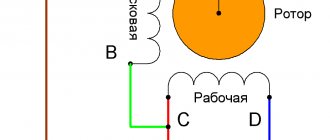
Brushed Motor Diagram - AC
This figure shows a universal diagram of the commutator motor Fig. 2. The circuit has three wire outputs from two stator windings, for connection to both alternating and direct voltages, that is, the motor is capable of operating on both direct and alternating current. Fig.2
The diagram shows the following designations:
Two ends of the wire from the three terminals of the stator windings are also needed to connect the smoothing filter of the capacitor.
Winding resistance - commutator motor
To measure the resistance of the stator windings of a commutator motor, you need to alternately connect the probes of the measuring device to the wire leads of photo 2.
Measurements of the resistance of the stator windings are carried out in order to determine their integrity or a break in the burnout of the wire in the winding.
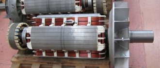
To measure the resistance of the rotor windings of a commutator motor, the resistance of the lamellas of the beginning and ends of the rotor windings connected to the metal plates is measured - on the collector photo 3, fig. 3.
And to check the absence or short circuit of the winding to the body of the rotor magnetic circuit, you need to connect one end of the probe of the device to the collector plate and connect the second probe to the magnetic circuit (Fig. 4.
When the rotor winding is short-circuited to the magnetic core body, the resistance for this section will take on a zero value.
In this topic, you got acquainted with the device and methods of diagnosing a commutator electric motor, and that’s not all.
The design of a modern car involves a commutator motor, a unit that uses contacts to determine the position of the rotor. Current trends in the global automotive market boil down to the complete replacement of power plants powered by internal combustion of fuel with electric motors. In recent years, calls for increasing the level of harmful emissions into the atmosphere have been heard almost daily, and this strengthens the position of electric units.
The operating principle of an electric motor is to convert electrical energy into mechanical work. If we compare units with internal combustion engines, electric motors are preferable; the advantage is: compactness, simplicity, durability, environmentally friendly and a lot of other advantages.
The design of a modern car involves a commutator motor, a unit that uses contacts to determine the position of the rotor.
Electric car Tesla model S:
Layout and operating principle
The moving part of a commutator motor, like any other, is mechanically balanced and secured in rotation bearings mounted in a stationary frame.
The stationary stator and rotating rotor have their own windings made of insulated wire. An electric current flows through them, creating magnetic fields with their own poles: north N and south S.
The interaction of these two electromagnetic fields creates rotation of the rotor.
Since voltage must be constantly supplied to both windings, and the rotor rotates, a special device is mounted for it: a commutator with a brush mechanism.
Areas of use
Despite the fact that in many areas there is an active replacement of brushed DC motors with brushless ones, brushed motors continue to be used in a number of applications:
- In many applications with stringent cost requirements, solutions that limit the use of complex and expensive control electronics
- In systems operating under harsh conditions (for example, high temperature or radiation) or where there are strict size restrictions.
Electrical diagram
For practical work, it is convenient to use two types of its representation:
Simplified display
The method allows you to very simply imagine the connection of all motor windings to the electrical network diagram.
The switch breaks both phase and zero potentials or one of them. Through the brushes with the commutator, a current circuit is created along the rotor windings.
Schematic diagram
Depending on the design features of the stator and rotor windings, they may have additional taps for powering various control and automation devices of the commutator motor or do without them.
Thermal protection prevents overheating of the motor winding insulation. It removes the supply voltage when the sensor is triggered, stopping the rotation of the rotor and actuator.
The tachogenerator allows you to judge the speed of rotation of the rotor. For some engines it is replaced with a Hall sensor. To transmit signals to these devices, collector plate contacts are also used.
Problem areas of the structure
Most often, malfunctions can occur in:
- bearings:
- brush commutator unit;
- layer of insulation of windings and wires.
Bearings
Their location is carried out at the edges of the rotor in such a way as to transmit the axial torque load as much as possible.
In ordinary household tools, they can be damaged for two main reasons:
- from incorrect load application:
- as a result of pollution.
Directions of effort
Bearings in household power tools are generally not designed to support lateral loads. From their frequent use, for example, when, when working with a drill, they do not load the end of the drill, but cut slot holes on its side, shaft beating is transmitted to the bearing mechanism, creating additional play of the balls in the cages.
Working in a polluted environment
The commutator motor has an air cooling system. The impeller, mounted on the rotor, takes air through special slots in the motor casing and drives it throughout the entire housing to remove excess heat from the heating windings. Warm currents are ejected through special holes.
If a dusty environment is created in the room, it will be sucked into the housing and penetrate the bearings and commutator-brush mechanism. There will be an abrasive effect on the parts that come into contact during rotation, their premature wear, as well as a violation of the electrical conductivity at the brush contacts.
Using a commutator motor for purposes other than its intended purpose, for example, collecting a flow of construction dust with a household vacuum cleaner instead of a construction one, is the most common cause of its breakdown.
Why do brushes spark?
Design features
When the engine is running, there is constant friction of the brushes against the contact plates of the commutator, which requires periodic inspection.
A slight layer of coal dust appears on the working surfaces of copper pads, as shown in the photograph. This is due to material consumption and brush wear.
This process always occurs when a commutator engine is running. Even with normal sliding of the brush, a slight break in the electrical current circuit is created. And this is always associated with sparking due to the occurrence of transient processes and the appearance of microscopic arcs. In addition, the windings have high inductive reactance.
Therefore, a fully operational brush mechanism sparks during normal operation, which is not noticeable to the naked eye, but is felt by sensitive electronic devices: televisions, computers and other equipment. Noise suppression filters are always installed in their power supply circuit. An example is the electrical diagram of a microwave oven shown on the website with a highlighted green fragment.
Wear of brush material
The current-carrying part pressed against the collector plate is made of coal. Its volume wears out and its length decreases. This weakens the pressure force created by the expanding spring.
This process may or may not be taken into account in different brushed motor designs.
Rare samples
On the old 1960 engine shown as an example, the spring is compressed by screwing the dielectric cap.
Types of commutator motors
For ease of perception in any area, there is a classification of products according to criteria, features, and functionality. As for collector installations, classification takes place according to different parameters.
Scheme of a universal commutator motor.
When classified by nutrition:
- Universal commutator motor;
- Collector unit (direction of movement of charged particles in an electric field = const);
- With permanent magnet inductor;
- With inductor on excitation coils:
- Excitation coil (independent winding type);
- Excitation coil (parallel winding type);
- Excitation coil (series winding type);
- Excitation coil (mixed winding type).
Universal collector unit.
The units are used in everyday life; a 220V AC commutator motor is used in household appliances. The motor consumes direct and alternating current. Popularity in use is due to reverse, rotation speed adjustment, and the need for a frequency above 3000 rpm.
Using a single-phase AC commutator motor, the stator and rotor windings are connected in series or parallel. No one makes the last connection option anymore. The universal single-phase collector unit works with alternating and direct current.
Disadvantages of the universal mechanism:
- Unit cost;
- Difficulty of maintenance;
- Noisy operation, complex controls, radio interference;
- The useful action is lower than necessary if an alternating current source is used;
- Wear of brushes due to the formation of sparks.
Collector unit (current = const).
Permanent magnet inductor.
The design difference from the universal installation is the use of magnets rather than field coils. The unit is popular and more widespread than other types of collector installations. The positive point is the cost and simplicity of the design. In addition, the device is easy to operate. The stumbling block is the magnets used, which are directly related to the power characteristics of the installation. The installation is affected by the field generated by the magnets.
| Positive aspects | Negative aspects |
| Significant torque at low speed; Wide range of adjustments; The price of the unit is affordable for consumers. | Low power; Aging of magnets, loss of properties. |
Commutator motor with permanent magnet inductor.
Excitation coils (independent and parallel)
The name of the type was obtained as a result of independent power supply. The peculiarity is that for torque to occur, the power supply of the inductor and the armature must be different, otherwise the rotor of the installation will not spin.
If it is not possible to organize the supply of different currents, then the connection is made in parallel. Both types are the same in terms of characteristics. The torque of power plants is high (even at low rotation), and as the frequency increases, the torque decreases. Feature: independence of the coil and armature. For the unit to fail, it is enough for the current exciting the coil to drop to the value “0”.
Independent excitation circuit:
| Positive aspects | Negative aspects |
| There are no magnets, so time does not affect the performance of the unit; Low speed - high torque; Easy adjustment, organized by the regulator. | The price is too high in comparison with opponents; A drop in the excitation coil current below the limit value is fraught with breakdown. |
Parallel excitation circuit:
Excitation winding (series type)
Sequence assumes equal current value. When the stator current is below the calculated value, the power of the magnetic flux decreases. The increase in load is comparable to the increase in flux power, until the limiting level is reached, when the increase in current does not increase the magnetic flux.
This feature does not allow the engine to start if the calculated load is below 25%. Having done this, there will be a sharp uncontrolled increase in rotation speed. This feature has left its mark on the use of the units; however, if the installation power is below 200W, the load may drop, even to idle speed.
| Positive aspects | Negative aspects |
| There are no magnets, so time does not affect the performance of the unit; The torque value is high, while the speed is insignificant. | The cost is too high, opponents are cheaper; The torque value decreases with increasing speed; Difficulties in adjusting the rotation speed of the unit; Operation without load leads to breakdown of the unit. |
Series excitation circuit.
Excitation winding (mixed type)
In such units, two coils are installed, connected in series and in parallel. The first has the status of the main one due to the ability to use a greater force of magnetism, the second has the status of an auxiliary one. It is possible to connect the coils using a counter or coordinated method. The selected connection determines what the field intensity will correspond to.
Read also: How to drill the ground for fence posts
You can connect a commutator motor if you need to obtain a constant frequency, or increase speed when the load increases.
Mixed excitation circuit.
| Positive aspects | Negative aspects |
| There are no magnets, so time does not affect the performance of the unit; Low speed - high torque; Reliability, tolerates boundary loads well; Simple control. | High price. |
The next step in the development of electric motors was brushless motors. The difference between a brushed motor and a brushless motor is that the latter lacks both a commutator and brushes. The function of the rotor in the engine is performed by magnets that are located around the shaft, and the windings are also located there. The rotor position is controlled by a sensor. Information from the sensor is processed by the computer. The unit has the positive aspects inherent in installations with a collector; it is not maintained; the only negative aspect is the high cost.
A vacuum cleaner, coffee grinder, drill, hammer drill, trimmer is not a complete list of equipment that uses the conversion of electrical energy into mechanical energy to operate household devices.
They contain complex technical components and require skillful handling, periodic inspection, and proper maintenance. When handled carelessly, various breakdowns occur.
The material in the article provides advice to a home craftsman working with electric tools or planning to independently repair an electric motor with a brush mechanism and commutator. The text is visually supplemented with diagrams, pictures and videos.
The information provided is collected in order to draw the attention of users to the rules for operating household appliances with a commutator motor. It will help you consciously identify emerging defects in a working circuit and promptly eliminate them.