Wire connection methods
There are several methods for connecting electrical wires. You can choose the most convenient and suitable option for your case.
Twist
Twist
Currently, connecting cables in junction boxes using the twisting method is prohibited - it is considered extremely unreliable compared to other existing options. By choosing twisting, you consciously accept all possible responsibility upon yourself.
How to properly splice and branch wires using twisting
The connection itself is extremely simple: approximately 10 mm of insulation is removed from the wires, and then they are carefully screwed onto each other. When connecting wires with a diameter of up to 1 mm, we perform at least 5 turns, in the case of twisting more “serious” cables - from 3 turns.
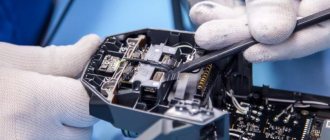
Crimping
Crimping tool
Popular connection option. It is performed using a special sleeve according to the size of the wire bundle. The sleeve material must also match the cable material.
To crimp the product, press pliers are used to crimp the sleeves. Craftsmen often try to perform crimping using pliers, but professionals recommend refraining from this option, because the connection will not be as reliable.
The work is performed in the following order.
We remove the insulation from the wires, focusing on the length of the sleeve used.
Second step
We twist the wires into a bundle and insert them into the connector.
We crimp the sleeve with the wires using press pliers.
Crimping process
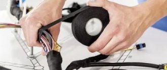
We insulate the finished connection with heat shrink or regular electrical tape.
Crimping process
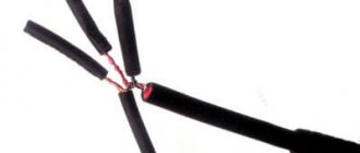
Welding
Welding
After making such a connection, you get essentially a solid wire, which is not afraid of either oxidation processes or other negative effects characteristic of detachable methods.
To connect wires using the welding method, you need to prepare the following:
- 24V welding machine with power from 1 kW;
- flux;
- carbon electrode;
- protective equipment (gloves, mask/goggles).
We work in this order.
We remove the insulation from the cables and strip the conductors until they shine. To do this we use sandpaper.
Second step
We connect the wires using the twisting method.
We pour flux into the recess of our electrode.
Twist welding machine TS 700 2
We turn on the welding machine, press the electrode against the cables and hold it until a ball forms - the so-called. "contact point".
Fifth step
Welding
We clean the resulting contact point from flux and cover it with varnish.
Finally, all we have to do is insulate the finished connection.
Soldering
Soldering
The procedure remains the same as when connecting wires by welding. The only difference is that the cables are connected using solder melted with a soldering iron. The molten solder should flow into the twist.
It is also not recommended to use soldering in areas of possible mechanical stress on the connection.
Screw terminals
Screw terminals
A great method for quickly and easily connecting wires in a junction box. Compact, inexpensive clamps allow you to connect both homogeneous and dissimilar conductors.
The job is done in two simple steps. You need to do the following:
- strip off approximately 5 mm of insulation from the ends of the wires;
- insert the wires into the clamp and tighten with a screw.
Bolted connections
Bolted connectionsWire termination
The connection is reliable, but very bulky. Suitable for the same bulky old-style boxes. In a modern box, a bolted connection may simply not fit.
The work is performed in the following order.
Second step
We put one of the wires to be connected on top of the bolt. First you need to peel off the insulation and form a ring from the cable. We do the same with the second wire in advance.
Fifth step
We put on the last washer and tighten the connection with a nut.
Of course, a bolted connection also needs insulation, which will not have the best effect on its dimensions.
Methodology for using RCD
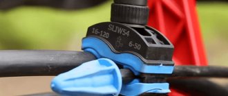
Self-clamping connections
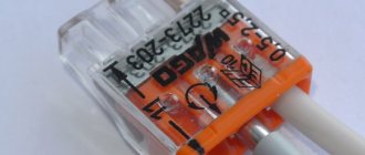
The most modern and popular option today. The clamps are extremely easy to use. In addition, such connections initially contain a paste that eliminates the risk of metal oxidation, which allows dissimilar conductors to be inserted into the clips without any fear.
We work in this order.
Self-clamping connections
First step. We remove approximately 10 mm of insulation from each wire.
Second step. Raise the clip lever up.
Third step. Insert the conductors into the connector.
Fourth step. We lower the lever down.
Clamps without levers simply snap into place.
Self-clamping connections
Why is it better to crimp (crimp) wires?
Wire crimping is one of the most reliable and high-quality methods of mechanical connections currently used. With this technology, loops of wires and cables are crimped into a connecting sleeve using press pliers, ensuring tight contact along the entire length.
The sleeve is a hollow tube and can be made independently. For liner sizes up to 120 mm², mechanical pliers are used. For large sections, products with a hydraulic punch are used.
When compressed, the sleeve usually takes the shape of a hexagon; sometimes local indentation is made in certain parts of the tube. In crimping, sleeves made of electrical copper GM and aluminum tubes GA are used. This method allows for crimping conductors made of different metals. This is largely facilitated by the treatment of the constituent components with quartz-vaseline lubricant, which prevents subsequent oxidation. For joint use, there are combined aluminum-copper sleeves or tinned copper sleeves GAM and GML. Wire connections using the crimp method are used for conductor bundles with a total cross-sectional diameter between 10 mm² and 3 cm².
Process description
The process of connecting electrical leads in a junction box is quite simple. If safety rules are followed, even a beginner can do this work. Before starting work, you should practice on individual metal parts to get used to the operation of the welding machine. You also need to learn how to regulate the temperature of the electrode so that it does not overheat and does not stick at the welding site.
The device is adjusted in accordance with the thickness of the wires that need to be welded and their number. First, using the usual twisting method, you need to fasten the wire strands. Strip about 5 cm from the end of the cord, removing the insulating winding. Then the contacts of the cores can be twisted together, making 6-7 turns.
Flux is poured onto the recesses. When welding, the electrode must be brought to the joint until a copper ball begins to form at the contact point. When the connection has cooled, you need to clean the contact from flux with sandpaper, and then insulate it with tape or heat-shrink tubing.
Soldering twisted copper wires
Let's start from the place where the wires are twisted in the junction box.
1. Twisting the wires in the box
In the left box, the wires are twisted according to the electrical wiring diagram. In principle, many electricians stop there. And they are 90% right, it can be insulated, such wiring will last 100 years, we don’t need any more. But this is provided that in this distribution. the box will always be dry and the circuit breaker has been selected correctly. I recommend my article about choosing a circuit breaker - How to choose a circuit breaker.
I saw that in old boxes there was a twisted connection between aluminum and copper. These were twists from 50 years ago! And everything worked great! This is very risky, and such compounds will live for a long time if several favorable conditions are met. Such twisting is usually subject to severe criticism among electricians, and it is considered extremely unprofessional. But we’ll forgive you, especially since those who made such twists are already in another world, where there is no need to connect wires...
Basic wiring diagrams
Above we talked in some detail about how to connect the wires in the junction box. However, the work is not limited to connecting wires in the junction box. You also need to connect the wires to sockets and switches.
Connecting sockets
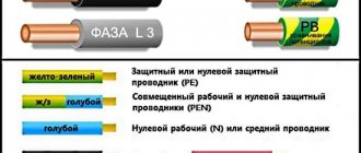
A group of sockets is usually separated into an independent line. There are three wires in the box, each of which has a color specific to its purpose. Brown is usually live, blue is neutral, and green/yellow is ground. In some cases other colors are used. For example, phase is red, zero is blue, ground is green.
Before laying, the wires are laid out to their full length and trimmed so that they are the same length. You need to have 10-12 centimeters of reserve - just in case. The connection of conductors is carried out using one of the methods described above.
If only a pair of wires is involved (where grounding is not used), then we are talking about neutral and phase. If the conductors are the same color, you first need to find the phase using a multimeter. For convenience, it is better to mark the phase wire with electrical tape or a marker.
Connecting a one-button switch
In the case of a switch, there are also three groups, but the connection is made a little differently. There are three inputs: from the junction box or electrical panel, from the lighting fixture, from the switch. The phase wire is connected to the switch button. From the output of the switch the wire is directed to the lamp. In this case, the lighting device will only work when the switch contacts are closed.
Connecting a two-button switch
In two-key switches, the circuit is somewhat more complex. A three-wire cable must go to the switch serving two groups of lighting fixtures (if grounding is not used). One conductor is assigned to the common contact of the switch, the remaining two are directed to the output of the buttons. The phase is combined with the common contact of the switch. The neutral wires from the input and two groups of lighting fixtures are connected. Phase wires from lighting fixtures and two conductors from the switch are combined in pairs: one from the switch to the phase of one of the lamps, the second from the switch to the other lamp.
Precautions during soldering
When soldering, especially with a crucible, you need to work very carefully so as not to get burned by the molten solder. Lead fumes are poisonous, so when doing large amounts of work you need to use a respirator.
What you absolutely cannot do!
It is unacceptable to use acid-containing active fluxes for soldering wires, since they require complete removal after completion of work. Flux residues have an aggressive effect on the material of the conductors and very soon the wires will be oxidized to the point of complete destruction. Zinc chloride or soldering acid are especially destructive to copper.
Read also: Is it possible to connect running lights to the dimensions
In this article I will look at the connection of copper wires in a junction box during electrical installation by soldering.
Despite the fact that I switched to Vago connectors, which significantly speed up the installation of electrical wiring, I still think that connecting wires by soldering is better. Now the welding devotees will attack me. But I won’t argue, I’ll just say that it’s more convenient for me, and the electrical and mechanical properties of such a connection are no worse than welding.
By the way, you know that 50-70 years ago radio equipment was assembled by welding. This applied to tube (there were no others) televisions and radios. And then we switched to printed wiring, which uses soldering. The soldering method requires higher technological preparation, but speed and ease of installation are everything.
So, I’m publishing a few photos illustrating the soldering of wires in a junction box. I will try to reveal all my secrets of such electrical installation. I hope my experience will be useful to my readers. Basically, for this purpose I write articles on SamElectric.
Soldering wires
The procedure for soldering conductors is as follows:
- Removal of insulation;
- Stripping wires;
- Maintenance;
- Twisting;
- Soldering;
- Isolation.
Before you start connecting the wires, you need to decide on their length. The wires are cut so that when soldered they are outside the junction box and can then be laid in the desired manner. Do not lay the wires under tension. Excess stock is also inappropriate in limited space.
To remove the insulation, use a sharp knife or a special tool (Figure 1).
Figure 1. Tool for stripping wires - stripper.
When working with a knife, the process of removing insulation should resemble the movements of a knife when sharpening a pencil. Do not make a circular cut into the insulation or trim it with side cutters or pliers. A transverse scratch or scratch on the wire can cause a break. As a last resort, this technique is allowed only on multi-core wires. The length of the bare conductor for soldering should be 1.5 - 3 cm. The thicker the conductor, the longer the stripped part should be. The number of turns when twisting the wires can serve as a guide. There must be at least 2 of them.
Before tinning, the surface of the cores must be cleaned from traces of oxide using a knife or fine-grained sandpaper. After stripping the wires, it is advisable to tin them immediately so that an oxide film does not form on the surface. The oxide formed on the surface of the solder is loose and will not interfere with subsequent soldering, so a break in work after the tinning stage has no time limit.
The tinned conductors are twisted together using pliers or pliers. The twist should consist of at least 2 turns. The twist should be tight, but not too tight, so that the stripped ends do not break off. The ideal variant of twisting is when part of the wire with insulation gets into it. The end of the twist must be even. When working with thick wires, they are often directed to the sides at the end of the twist, so the protruding ends must be trimmed. The figure below shows various ways to twist solder wires (Figure 2).
The twisted wires are soldered using a soldering iron so that the twist is evenly covered on all sides with a layer of solder without gaps or sagging. The quality of the soldering directly depends on how well the stripped ends were tinned.
After the soldering area has cooled down, you can begin insulating it. For these purposes, fabric insulation or special heat-resistant plastic tips are used. Their length should be such that they partially extend onto the insulated sections of the wires (Figure 3).
Figure 3. Isolation of adhesions using plastic caps
You cannot use ordinary PVC electrical tape for insulation, because when the wires heat up, for example, when the load is exceeded, PVC easily melts and this can lead to a short circuit inside the junction box.
Selecting the power of the soldering iron
For high-quality soldering you need a fairly powerful soldering iron, at least 65 W. Copper is a very good conductor of heat, so it effectively transfers heat away from the soldering area. A low-power soldering iron will not have time to heat the twisted area before the wire insulation begins to melt, and insufficient heating can lead to so-called “cold soldering.” Weakly heated solder has low fluidity and is not able to evenly cover the entire soldered area. When hardened, it will have a matte, grainy surface and low strength. Conductors soldered in this way will have a high contact resistance and, over time, will lose contact with each other. The soldering iron should warm up the soldering area in no more than 1 minute. The surface of the solder after hardening should be smooth and have a uniform shine.
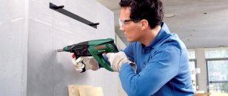
How to install bored piles correctly
When drilling wells for piles, a hand drill is used if the wells must be 300 millimeters wide; if you need holes at least 1.5 times wider, you will have to use an electric or motorized drill. Experts recommend this, and the sequence is as follows:
- Using roofing felt and soft steel wire, formworks are made, the diameter of which is the same as that of the well, and higher - by 20-30 centimeters. The roofing material at the top is rolled into 2-3 layers and secured with wire. You can also use ready-made cement-asbestos pipes.
- Sand is poured onto the bottom and the manufactured “pipes” are inserted into the wells. You need to carefully ensure that they rise at the same height.
- Reinforcement is inserted inside the support. It should be such a length that it is driven 30 centimeters into the ground and protrudes the same amount above the support.
- Before installing the reinforcement, you need to make sure that it is not affected by corrosion and coat it with a composition that prevents it, for example, epoxy resin.
- Concrete is poured inside and outside the support. The flow is the same gradually as in the previous case. If there is no vibration press, the air is “released” by piercing the still liquid concrete with a rod in several places.
A slightly different method involves the following actions:
- Concrete is poured into the pipe one third of the way.
- Having raised the formwork by 10 centimeters, they allow a certain amount of concrete to flow out to the bottom and press it in with force: the platform formed below will firmly secure the formwork. Then the reinforcement is inserted, but so that it does not protrude from the pillars.
- When the concrete is poured to the brim, a special threaded pin is inserted so that it protrudes 30 centimeters.
Soldering standardized cables
Now let's pay attention to the wires used when connecting all kinds of electronics and equipment.
Cables with RJ 45 connectors
RJ45 cable
Another name is twisted pair. They are used to connect a computer to a wired Internet, routers and switches, or to connect several machines into a local network. The wires in these cables are not soldered to the connectors, but simply crimped with a special tool.
A soldering iron may only be needed if the cable itself is damaged. The conductors are marked in different colors, so it is difficult to make a mistake. But we will still describe the order in which rj 45 4 wires are wired to the connector.
For connecting to routers, etc. in addition to connecting computers with each other
Direct order is used here (at both ends of the cable, the wires are connected in the same way). Let's go from bottom to top:
- brown;
- brown with white stripe;
- green;
- blue with white stripe;
- blue;
- green with stripe;
- orange;
- orange with stripe.
To connect machines to each other
In this case, the order is slightly different, it is called a cross connection, although it is no longer necessary to use it, since modern machines can themselves determine the type of wiring and adapt to it, but if you are dealing with outdated equipment, then we connect the wires as follows.
We connect on one of the connectors, as in the first case. On the second, the order changes if you go from below:
- brown;
- brown with stripe;
- orange;
- blue with stripe;
- blue;
- orange with stripe;
- green;
- green with stripe.
XLR connectors
xlr to jack cable
These connectors are designed for connecting microphones, pickups and high-quality audio equipment. The peculiarity of these cables is that the signal in them is transmitted in two polarities along a twisted pair of wires. This is done for better protection against interference.
A problem that often arises is that a microphone with this connector needs to be connected to a computer, which most often has TRS (Jack in common usage) sockets installed. Also, it is often necessary to connect XLR to other types of connectors, or a longer wire is required.
You can, of course, look for adapters in stores, but they are quite rare there. But there is a second way - if our instructions helped you master soldering, then you can make a cable with your own hands in 5-10 minutes.
For this you need:
- XLR connector;
- two-core shielded wire;
- Jack connector or any other type to which we will make an adapter.
Then everything is simple - we prepare and solder the wires in accordance with the diagram shown in the photo below.
XLR Connector Wiring Diagrams
They are drawn here (we count the drawings from top to bottom).
- The wiring of the xlr jack wire is balanced (protected from interference).
- The wiring is xlr xlr balanced.
- The xlr jack wiring is not balanced.
- RSA -xlr is not balanced.
- xlr - jack stereo, unbalanced.
The wire labeled “Ground/Shield” is the shield.
Advice! It is convenient to solder wires to the contacts of the plug by inserting it into the socket of a faulty or at least disconnected device.
USB cables
USB cable
USB is the most common connector format today. They were originally developed to connect computers and peripherals, but today almost all mobile devices use USB not only for data transfer, but also for charging.
Although it is not difficult to purchase a new cable to replace a damaged one, you can still make repairs yourself. This can help in critical situations when the store is inaccessible or you do not have time to visit it.
USB wiring is not complicated, all wires are of different colors depending on their purpose. Moreover, there are three twisted pairs of the same color in versions 3.0 (this is done to increase speed), but they are connected in parallel to the same pad.
- Red - power (+5V or VCC).
- White - negative data (D-).
- Green – data plus (D+).
- Black - ground (GND).
- Purple - used to implement OTG (ID designation);
- The screen is without color and is connected to the body.
The fifth purple wire is not used.
Location of contacts in regular (not micro and mini) plugs
The wires are connected in the following way. In type A (flat) connectors, they are connected in order (from left to right, if you place the plug with the contact pad down and look from the side where the wires are connected).
In type B plugs, the arrangement is as follows (the plug lies with the beveled edges up) from left to right:
- Top row 2.1;
- Bottom row 3,4.
Micro and mini plugs
In the same way, we look from the side where the wires are connected (the contact pad is at the bottom):
- Mini type A is connected as follows - 4,5,3,2,1.
- Mini type B - similar to the previous one, only the 5th wire is not connected at all, and the contact remains empty.
- Micro type A - 1,2,3,5,4.
- Micro type B -1,2,3,4 the platform for the fifth wire is empty.
That's all we wanted to tell you about connecting wires by soldering and repairing cables of various standards. We will be glad if we helped you master the technology of performing work and learn all the secrets of a soldering iron with which you can achieve quality. Do simple repairs yourself, save time and money.
Soldering and tinning technology
In order to solder or tin the wires, they must be positioned so that they are as horizontal as possible and there is access from all sides for the soldering iron tip. Contrary to many recommendations, you cannot place the twist vertically, because when soldering, drops of molten solder can roll off the twist and damage the insulation in the underlying conductors.
If such a drop is not detected and removed in time, it can subsequently cause a short circuit. For better contact of the soldering iron tip with the wire, the end of the tip should be flat and well tinned. An oxidized tip has a dark color, does not hold solder and is not suitable for soldering. You can clean the tip using a fine-grained file. The stripped end is immediately dipped into flux and tinned by rubbing a drop of solder onto the surface of a block of wood (Figure 4).
Figure 4. Tinning the soldering iron tip
Tip #2. It is convenient to combine stripping and tinting on a piece of sandpaper, sprinkled with rosin powder and small pieces of solder in advance.
A well-tinned tip should be shiny and free of shells. When melting solder, it should remain at the end of the tip in the form of a small bulge (Figure 5).
Figure 5. Correctly tinned soldering iron tip.
For tinning, the wire is heated with a soldering iron and, at the same time, a piece of rosin is touched to the heating site until it melts. Liquid flux is applied in advance, before heating begins. By moving the soldering iron tip along the wire, evenly cover it with a layer of solder. Stranded wires are not tinned before twisting, since it will be impossible to twist them later.
The tinned wires are twisted together. For soldering, the technology is somewhat different, since it requires a larger amount of solder. After applying the flux, use a soldering iron to simultaneously heat the twist of the tip of the solder rod. The molten drop is evenly distributed over the entire surface, making sure that it is completely covered with a layer of solder. If necessary, repeat the procedure. The main thing here is not to overheat the wires so that the insulation does not melt. When soldering thin wires, the solder is transferred to the tip of the tip. Stranded wires require a large amount of flux so that it can fill all the free space between the cores.
Soldering with crucible and torch
For large volumes of work, it makes sense to perform them using a crucible, which is a hollow metal cylinder with a handle filled with molten solder. The crucible can be used as an attachment to a powerful soldering iron or heated using a gas burner (Figure 6).
The large volume of metal in the crucible does not allow it to cool quickly, so a heated crucible can solder several strands in succession. The main advantage of this soldering method is that tinning and soldering of the twist occurs almost instantly when the flux-coated conductors are completely lowered into the solder bath.
Which connection is better?
The choice of connection depends on a number of criteria:
- wire material (same or different);
- number of wires in the connection;
- wire diameters (same or different);
- experience and skills of the master, availability of additional tools;
- Is a detachable connection required?
For the average person, it is easier to connect the wires using terminals or a bolt method.
The first, despite the relatively high cost of the terminals, is more preferable, since the bolted connection is large in size and will not fit in every junction box. The disadvantage of terminals is the danger of running into a fake or choosing the wrong product based on the rated current.
The most reliable, durable and high-quality connection method is welding. But this requires a welding machine - quite specific equipment that not everyone has. That’s why professionals often choose crimping with sleeves.
Soldering is practically not used when organizing connections in a junction box for the following reasons:
- it is extremely difficult to solder wires located under the ceiling, especially if there are several of them in the connection;
- over time, the resistance of the soldered joint increases, which, given the high current intensity inherent in power circuits, produces noticeable heating;
- low-melting solder melts during short circuits (short circuits) and even overload, as a result of which the contact in the connection is broken.
Soldering is usually used in low-current switching lines. Many professional electricians speak highly of PPE. One installation company reports on its website that it has been using such clamps for more than 15 years and they have never failed. Employees of this company use Wago terminals only at the insistence of the customer, since, in their opinion, the plastic parts of these products often melt under prolonged maximum load.
To connect aluminum and copper wires, a special sleeve is required - brand GAM or GMA. As experienced electricians testify, it can be difficult to find it on sale.
What's new in the VK SamElectric.ru group?
Subscribe and read the article further:
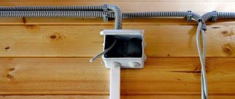
7. Closed boxes. Flush
You definitely don’t have to worry about contact in such boxes; you can completely bury them under a layer of plaster. Although, it’s better, of course, to have access to the boxes, you never know – check, connect additionally, etc.
Recommendations
Some useful tips have already been given, but I would like to highlight some additional recommendations. For example, how much solder is needed for the soldering to work properly. It’s impossible to say for sure here, but if there is not enough solder, then there will not be enough to cover the entire joint. If there is a lot of it, the soldering will end up in the form of a drop, which is also unacceptable, especially in a gasket system (in a bundle).
The same applies to the temperature of the soldering iron. If it is low or too high, then the soldering turns out to be unshiny and loose with low quality indicators. This fully applies to the amount of rosin and solder. If there is more rosin than solder, then the former will boil and splatter, which is very bad for adjacent connections and contacts.
If all of the above is normal, then the solder itself will be evenly distributed over the connection. The shape of the solder and its strength will form by itself. And one more point: soldering copper wires (quality) means preparing them, that is, tinning. Without this, the connection process cannot be carried out, because pure copper wires can be connected either by riveting or welding.
Beginners can be advised to first determine how long it takes for a soldering iron to overheat. If it takes ten to fifteen minutes, then it is better to purchase an additional transformer with smooth voltage regulation or an electronic thermostat. By the way, you can determine that the tip of the soldering iron is overheated very simply - the solder has flown off the tip of the tip, which has turned black (oxidized). Of course, you don’t have to buy additional devices, then during the soldering process the tool will have to be periodically disconnected from the network. Although this method is not the best, because it is almost impossible to control the temperature in such a situation.
And the last piece of advice in our article is to never artificially cool the soldering area. Cooling should occur naturally. Do not blow on the connection or apply wet objects to it.
Solder type of soldering iron
Among the many types of solder, only a few can be used for soldering copper wires. Table of characteristics of the most common brands of solders
Solder grade
Application area
Read also: Soldering iron with loop tip
The first three brands of solder have a very low melting point and low strength. They are not suitable for soldering high-current circuits. On the contrary, the latest brand of solder is too refractory. Soldering with such solder will lead to overheating and melting of the insulation. The most commonly used solders are POS-40 and POS-61 brands. They are inexpensive and widely available. Most radio amateurs use POS-61 solder in their work.
Twist connection
The easiest way to connect wires is twisting. Previously, this was the most common method, especially when wiring in a residential building. Now, according to the PUE, connecting wires in this way is prohibited. The twist must be soldered, welded or crimped. However, these methods of connecting wires begin with twisting.
In order to perform high-quality twisting, the connected wires must be cleared of insulation to the required length. It ranges from 5 mm when connecting wires for headphones to 50 mm if it is necessary to connect wires with a cross-section of 2.5 mm². Thicker wires are usually not twisted together due to their high rigidity.
The wires are stripped with a sharp knife, insulation stripping pliers (ISR) or, after heating with a soldering iron or lighter, the insulation is easily removed with pliers or side cutters. For better contact, bare areas are cleaned with sandpaper. If the twist is supposed to be soldered, then it is better to tin the wires. Wires are tinned only with rosin and similar fluxes. This cannot be done with acid - it corrodes the wire and it begins to break at the soldering site. Even washing the soldering area in a soda solution doesn’t help. Acid vapors penetrate under the insulation and destroy the metal.
The stripped ends are folded parallel into one bundle. The ends are aligned together, the isolated part is held firmly with your hand, and the entire bundle is twisted with pliers. After this, the twist is soldered or welded.
If there is a need to connect the wires to increase the total length, then they are folded opposite each other. The cleaned areas are placed crosswise on top of each other, twisted together by hand and tightened tightly with two pliers.
You can only twist wire made of the same metal (copper with copper, and aluminum with aluminum) and of the same cross-section. Twisting wires of different sections will turn out uneven and will not provide good contact and mechanical strength. Even if it is soldered or crimped, these types of wire connections will not ensure good contact.
Connecting wires by twisting and soldering - what does the PUE say?
Let's start with the fact that twisting wires in electrical installations is prohibited. At least in the PUE, twisting is not allowed (PUE, Chapter 4.2). This can be explained by the fact that the quality of twisting depends very much on the experience, tool, and even the mood of the electrician. And there is no way to check this quality, you can only evaluate it “by eye” or test it with increased current.
Soldering is also not allowed, this is stated in the PUE there. This is motivated by the fact that in some emergency conditions the connection temperature can reach 300°C, the solder will melt and drain. Honestly, I can’t imagine how this can happen if the circuit breakers are installed with the required rating. But even if this happens, in my opinion, such wiring will need to be completely changed! And it won’t matter whether the solder melted or not.
As for crimping - yes, the method is good, but it requires additional equipment (press molds) and consumables (sleeves). The same goes for welding - you need a transformer (inverter) and graphite rods. And experience - how many times have I seen that the ball at the end of the twist fell off due to excess current, or did not grab all the wires in the twist due to low current.
Therefore, I believe that twisting followed by soldering is the best way to connect wires in junction boxes. The soldering iron is lightweight, the price is low, the solder and rosin are cheap.
Next - more about this hot smelling process)
Required tools and materials
Before soldering two wires, you must first purchase all the necessary materials, and also stock up on the most important device - a soldering iron.
Soldering iron
This device is a heating device; it is used to heat the solder alloy and the surfaces of the parts that need to be soldered. It has three main parts:
- handle (it is made of wood or plastic, it does not heat up during operation);
- a heating element;
- work item.
Soldering irons come in different types:
- Electric heating. The working part of such a tool is the tip of a copper tip, which is heated by a heating element. The temperature of the tip reaches 300 degrees, and it is not very powerful (from 60 to 100 W).
- Gas. According to the principle of operation, this soldering iron is similar to an ordinary gas torch; the place where soldering should be done is heated using an open flame.
- Thermal air. The soldering area is heated with hot air.
- Hammer. The working part of this soldering iron is also a copper tip, but its shape resembles a massive hammer. Heating occurs using an open flame or due to the built-in electric heating element.
The most widely used electric heating soldering iron is for soldering radio components and wires.
Solder
The main material in the soldering process is solder. It is an alloy of several metals, which has a lower melting point than the metal of the elements being joined. Such alloys are made from tin, cadmium, silver, copper, lead, and nickel.
It is advisable to solder copper wires using POS-60 alloy. The letters POS indicate that this solder is made of tin and lead. The numbers show what percentage of tin is contained in the solder. Of course, pure tin is considered the best solder material, but it is expensive and is used in exceptional cases.
Solder comes in different forms - granules, pastes, ingots, powder, foil or wire.
How to use solder alloy? It is heated above the melting point and, when it reaches a molten state, it is touched to the solid surfaces of the elements being connected. At this moment, chemical and physical processes begin. The solder alloy spreads over metal surfaces, penetrating into all the gaps between them.
Keep in mind! Before you solder the aluminum wires, you will need to find a special solder. For this metal, zinc-based alloys TsO-12 (zinc with tin) or TsA-15 (zinc with aluminum) are more suitable.
Flux
Most often, a mixture of organic and inorganic substances is used as a flux, with the help of which surfaces are prepared for soldering. This can be rosin, acetylsalicylic or phosphoric acid, ammonia or borax salt.
The most common flux is rosin. Some people use acid for soldering, but it is inferior in quality to rosin. Although it is much easier to use acid, we soaked a brush in it and applied the substance to the surfaces to be joined. With rosin it’s a little more complicated; you need to place a core in it, heat it with a soldering iron, then the resin will begin to melt and envelop the wire.
Sometimes they use solder, which is a thin wire filled with rosin inside. Of course, this makes the process faster and more convenient; all you need to do is take solder with a heated soldering iron and apply it to the surfaces to be connected; there is no need to treat each wire with rosin separately.
Other tools
Also, in order to solder the conductors, you will need:
- The place to work must be covered with a material that will not be afraid of drops of molten solder. A metal table or some kind of stand made of metal or wood is suitable when work needs to be done, for example, in a distribution box.
- Stand for soldering iron (it should be reliable and comfortable).
- A piece of damp cloth or sponge for wiping the soldering iron tip.
- File. Before using a soldering iron, you will first need to clean its tip; there should be no traces of soot on it, then soldering will go easily.
- A knife or a special device for removing the insulating layer from wires.
- Pliers.
- Sandpaper.
- Alcohol.
- Insulating tape (or heat shrink tubing).
Methods for soldering aluminum wires
Despite the fact that in modern construction, during electrical work, aluminum cables are increasingly being replaced by copper cables, aluminum remains an indispensable material in the manufacture of large-section wires and cables.
The reasons for this lie on the surface - the electrical resistivity of aluminum is approximately one and a half times greater than that of copper, and the volumetric weight is three times less.
With a large conductor cross-section, when weight is more important than strength, the choice in favor of aluminum is obvious. The cross-sectional area of an aluminum conductor will be one and a half times greater than that of a copper conductor, and at the same time, aluminum will still be two times lighter than copper. Soldering, among other methods, is used to connect wires.
Soldering methods
The problem with using aluminum conductors is their rapid oxidation.
The oxide film significantly impedes the passage of electric current during connections. To do this, twisted aluminum wires are soldered. You can solder aluminum wires in a junction box using a soldering iron or a gas torch. It is more difficult to use a soldering iron due to the inability to accurately heat to the required temperature. And for aluminum, overheating is just as unacceptable as underheating.
Metal has high thermal conductivity, and the insulation over a large area from the soldering point can simply melt.
It is easier to regulate the heating temperature with a gas burner, but it takes a long time to prepare the surface. However, it is the torch that will need to be used if it is necessary to solder any massive parts to each other. In any case, when soldering aluminum wires, they need to be prepared.
Preliminary processing
The difficulty with soldering is that aluminum itself is a very low-melting material (660 ℃) and if heated carelessly it can melt.
Another factor that makes soldering aluminum wires difficult is rapid oxidation in air.
The oxide film on the surface of the material reliably protects aluminum from the effects of all kinds of external factors, but it also prevents the adhesion of solder to the material and must be removed.
It is almost impossible to mechanically remove the oxide film under normal conditions. The material is instantly oxidized and covered with a new film. You can mechanically remove the oxide film under the oil layer.
But before this, the oil must be heated to 200 ℃ in order to remove any active oxygen that may be present there. This method is very inconvenient at home and labor-intensive.
Therefore, the ends of aluminum conductors must be tinned before soldering. Using rosin or most other fluxes will not work due to the high chemical resistance of the oxide film. It does not dissolve even with organic acids.
To tin the wires, you must use both a special flux and a mechanical method.
Of course, this must be done before the wires are twisted, otherwise it will not be possible to mechanically clean the entire surface of the wire. Only the tinned ends can be twisted together and soldered.
Working with a soldering iron
In order to solder aluminum with a soldering iron, there are several methods, the essence of which is to clean immediately under the flux layer in direct contact with the molten solder.
The first method is that aluminum conductors, before soldering, are cleaned with a hot tinned soldering iron using a mixture of rosin and steel filings.
Sawdust has an abrasive effect, rosin removes all impurities and immediately the cleaned areas are covered with solder, which should be on the soldering iron tip.
The second method involves stripping the aluminum wire on medium-grit sandpaper directly under the influence of a hot soldering iron with solder and flux.
Gas burner
Processing with a gas burner is carried out when the parts are in the position relative to each other in which they will be used.
The processing smoothly transitions into the soldering process itself. This happens as follows:
- the burner heats the surfaces of aluminum parts;
- upon reaching the temperature at which the metal is reduced from the oxide, the film is mechanically peeled off;
- under the influence of a flame, the parts are coated with flux, and solder is introduced into the soldering area.
If the parts are thick, then their edges must be cut at an angle of 45°. Typically, heating occurs to the melting point of tin, when the solder spreads and fills the twist groove.
Differences in technology when using flux
Thanks to the achievements of modern science and technology, flux compositions for aluminum have been obtained that actively dissolve the oxide film and protect the material from further oxidation.
Examples of such drugs are formulations labeled F-59A and F-61A. The letter A means that these compounds are intended for soldering aluminum.
When using these fluxes, soldering aluminum wires is greatly facilitated. It is enough to simply treat the finished twist with flux, without even heating it, and then, after heating it with a soldering iron or torch, apply solder.
Soldering. Connecting wires by soldering.
Soldering is a method of joining metals using another, more fusible metal. Compared to welding, soldering is simpler and more affordable. It does not require expensive equipment, is less fire hazardous, and the skills needed to perform good quality soldering will require more modest skills than when making a welded joint. It should be noted that the metal surface in air is usually quickly covered with an oxide film, so it must be cleaned before soldering. But the cleaned surface can quickly oxidize again. To avoid this, chemicals are applied to the treated areas - fluxes, which increase the fluidity of the molten solder. This makes the soldering stronger.
Soldering is also the best way to terminate copper strands into a ring - the soldered ring is evenly coated with solder. In this case, all wires must completely fit into the monolithic part of the ring, and its diameter must correspond to the diameter of the screw clamp.
The process of soldering wires and cable cores consists of covering the heated ends of the connected wires with molten tin-lead solder, which after hardening provides mechanical strength and high electrical conductivity of the permanent connection. The soldering must be smooth, without pores, dirt, sagging, sharp bulges of solder, or foreign inclusions.
To solder copper conductors of small cross-sections, use solder tubes filled with rosin, or a solution of rosin in alcohol, which is applied to the joint before soldering.
To create a high-quality soldered contact connection, the wire (cable) cores must be thoroughly tinned, and then twisted and crimped. The quality of the soldered contact largely depends on correct twisting.
After soldering, the contact connection is protected by several layers of insulating tape or heat shrink tubing. Instead of insulating tape, the soldered contact connection can be protected with an insulating cap (PPE). Before this, it is advisable to coat the finished joint with a moisture-resistant varnish.
Heating of parts and solder is carried out with a special tool called a soldering iron. A prerequisite for creating a reliable connection using soldering is the same temperature of the surfaces being soldered. The ratio of the temperature of the soldering iron tip and the melting temperature is of great importance for the quality of soldering. Naturally, this can only be achieved with the help of a properly selected tool.
Soldering irons vary in design and power. To perform household electrical work, a conventional electric rod soldering iron with a power of 20-40 W is quite sufficient. It is advisable that it be equipped with a temperature regulator (with a temperature sensor) or at least a power regulator.
Experienced electricians often use an original method for soldering. In the working rod of a powerful soldering iron (at least 100 W), a hole with a diameter of 6-7 mm and a depth of 25-30 mm is drilled and filled with solder. In a heated state, such a soldering iron is a small tin bath, which allows you to quickly and efficiently solder several multi-core connections. Before soldering, a small amount of rosin is thrown into the bath, which prevents the appearance of an oxide film on the surface of the conductor. The further soldering process involves lowering the twisted connection into such an improvised bath.
Soldering wires quickly and efficiently using a simple device
Authorization on the site
Soldering wires is one of the most reliable methods of connecting electrical wires, prescribed in regulatory documents.
We make a homemade device for quick and high-quality soldering. Soldering twisted wires has always been one of the most reliable methods of connecting wires; it was used by our grandfathers. Recommendations are based on many regulatory documents.
But the procedure for soldering twists is quite complicated, for example, many use gas torches, this requires additional gas costs, and in addition there is a risk of damaging the insulation on the wires.
Someone solders with a hair dryer - this is also a good method, but very labor-intensive. I also saw guys who made special devices from an iron for heating tin and dipping twists, but my method seems much simpler to me.
So let's share it.
The first thing you need to make is a crucible.
Let me explain, for those who don’t know, the crucible
- this is a small container made of heat-conducting material for melting metals; they are used in jewelry, for example, gold is melted in graphite crucibles.
A lathe turned the crucible for me from a copper blank, but now in the age of the Internet you can very easily buy it from graphite.
I drilled a hole in the body of the turned blank and cut the thread. I also cut a thread on the tip of an old Soviet screwdriver; it will serve as a handle so as not to get burned.
Wire soldering process
Now about the most interesting part - the soldering process.
We prepare all the twists in the distribution boxes.
We put solder in the crucible and heat it with a gas burner.
After heating the solder, dip the twists one by one into the molten solution, holding the crucible by the handle.
The soldering process takes a few seconds, and during soldering of heated solder it will be about 10-15 minutes, during which time you can solder, well, maybe not a hundred, but a decent number of twists. After the solder hardens in the crucible, it does not go anywhere; the next time it is heated, it can also be used.
Here's a simple soldering method.
By the way, if you cut the twist and look, you can immediately notice the high quality of the soldering.
Well, that’s all, thank you for reading to the end, I have already written several publications about other reliable methods of connecting wires, they can be seen below in similar homemade products.
A quick connection with big consequences
We often don’t think about the consequences of such a “simplification”. Meanwhile, an unreliable contact will fail at the most inopportune moment; the power supply to consumers/power receivers can always be cut off. Voltage “surges” cause breakdown of the elements of the power cascades of complex SBT household appliances. Even special protection devices used in the most “sophisticated” models of foreign manufacturers cannot save you from breakdown.
The induction of short electromagnetic pulses with a voltage of several thousand volts onto the electronic filling causes “harmless” sparking at the joints. At the same time, the standard protection equipment with which apartments are now equipped (RCDs, circuit breakers, fuses) do not “see” such short low-current pulses, so they simply do not trigger them, and we do not accept installing special devices for this. Uninterruptible power supplies for computers also did not become a panacea for transient impulses. The occurrence of “poke” causes malfunctions in the operation of electronic equipment and computer equipment, leading to failure of electrical components and expensive functional modules. Overheating at the site of a poor connection leads to even more catastrophic consequences; when current passes, the weakened connecting node becomes red-hot. This often causes fires and fires, causing enormous damage to the owners of the premises. Statistics show that 90% of all electrical wiring faults occur due to twists and poor contact connections of conductors. In turn, the very malfunction of electrical wiring and equipment, according to the Ministry of Emergency Situations, is the cause of one third of the fires that occur in Russia.
However, it so happened historically that several decades ago, in conditions of a shortage of electrical accessories/copper conductors, twisting aluminum wires was considered the main method used in electrical installation work. Twisting as a connection can be used in electrical engineering when carrying out repair and restoration work.
Other types of flux
- Fluxes with pronounced anti-corrosion properties. These are compounds based on phosphorus acid and a solvent, which when interacting form organic compounds. They are very beneficial to use because after the soldering process there is no need to use special cleaners;
- Liquid fluxes made from salicylic acid, petroleum jelly, gold and ethyl alcohol. This is the most convenient connection for radiators and soldering electrical wires. This flux ensures high seam cleanliness and neatness;
- In order to produce neutral flux for electrical devices with high precision requirements (time relays, switches, for connecting mobile phone contacts, etc.) you will need rosin-air connections. Rosin is very low-active and should only be used on prepared metals, previously cleaned and tinned; Rosin
- Activated fluxes are borax and rosin. In most cases it is used for plumbing connections and soldering of copper pipes. The main difference is the fact that borax melts at a temperature of 70 degrees, without releasing absolutely any harmful compounds. This is only one variety;
Borax - In order to prepare activated fluxes, you can use the following recipe: mix rosin, aniline, add a little anhydride, salicylic acid and diethylamine. This is a good option for making soldering for assembly fasteners.
Read also: Features of a metal crystal lattice
Selecting and preparing a soldering iron
This is perhaps the most crucial stage. A poorly chosen or improperly prepared tool will not produce high-quality soldering.
Power and type
The main criterion for choosing a soldering iron is its power. The industry produces instruments with power from 10 to 200 W and higher. The former can be the size of a fountain pen, the latter look like a natural hammer of impressive size.
Electric soldering irons with a power of 30 (left), 60 and 200 W.
All that remains is to decide which soldering iron to choose for soldering wires. Here everything will depend on the operation being performed, or more precisely, on the thickness and massiveness of the parts that need to be soldered. The more massive the parts, the greater the heat capacity the tool should have. An approximate dependence of the recommended soldering iron power on the task being performed can be presented in the following table:
- 15-25 W – small radio elements, microcircuits, conductors with a diameter of up to 0.3-0.5 mm;
- 30-40 W – large radio elements, wires with a diameter of up to 1 mm, including multi-core ones;
- 40-60 W – fairly large parts, conductors with a diameter of up to 2 mm;
- 100 W – massive parts, wires with a diameter of up to 3-4 mm;
- more than 100 W – power wiring with a diameter of more than 4 mm.
If you don’t have a soldering iron with the necessary characteristics at hand, you can take a slightly larger one in power, but not vice versa. With a massive device, it is possible to solder thin wires with a certain skill, but with a small and low-power thick one, it is almost never possible. Ideally, your household will have several electric soldering irons of varying power.
But what to do if there is no soldering iron of the required power or if it does not exist in nature at all? Trying to solder busbars into a pencil thick with a 100-watt soldering iron? In no case! In this situation, regular fire will help. Place the parts prepared for soldering, for example, in the flame of a household gas burner or alcohol lamp and solder. Additional heating will help to perform high-quality soldering even with low-power tools. The only thing is, when heating the wires over an open flame, do not overdo it - a little additional heating is enough.
Separately, it is worth noting the so-called “pistol” or pulse soldering irons, which were widely used, and even today are in service with craftsmen on the road.
A modern version of a pistol soldering iron.
At first glance, the advantages of such a device are obvious - it heats up instantly and cools down just as quickly. But this feature is convenient only for a narrow circle of specialists - on-call specialists. He came, took it out of the suitcase, poked it, put it in the suitcase, took the money and left. But anyone who has seriously worked with such soldering irons knows very well their shortcomings.
The device is literally too heavy to lift, does not maintain the optimal temperature, and the shape of the tip, which burns catastrophically, is extremely inconvenient. As a result, soldering with a similar tool with a wire loop instead of a tip can be characterized by the phrase “ugh, looks like I’m drooling.” A pistol electric soldering iron is at least suitable for repairing a Record tube TV, and a Whirlwind vacuum cleaner, but nothing more. There can be no question of high-quality soldering, especially of wires.
Sharpening and servicing the tip
After the soldering iron is selected, it must be prepared - sharpened and tinned the tip. There are many types of sharpening tips:
Unified forms of soldering iron tip sharpening
Which one to choose depends on your personal preferences and habits. For soldering wires, the most optimal sharpening points are Nos. 3, 4 and 5. After sharpening with a regular file, the tip must be immediately tinned - covered with a layer of solder. Why do you need to do this? Briefly, the soldering process is as follows: a drop of solder is applied to the tip of a heated tip, which is subsequently transferred to the parts being soldered. But how to work with a finger tip, the untinned tip of which is covered with copper oxide and is absolutely not wetted by solder?
So, if the tool tip is sharpened or simply cleaned to a copper shine, it’s time to move on to servicing. To do this you will need regular soldering rosin and a piece of solder. Plug in the electric soldering iron and slowly, without pressing, rub the cleaned area with a piece of rosin. As the soldering iron heats up, the rosin will begin to melt and cover the tip with a thin layer.
Quickly put the rosin aside and pick up the solder, trying to “paint over” the area covered with rosin with it. As the soldering iron continues to heat up, the solder will also begin to melt and spread evenly over the tip. The operation can be considered completed. If nothing works on the first try, do not despair - cool the soldering iron (it is useless to clean the hot tip - it will immediately oxidize), repeat the cleaning and tin again.
Tool temperature
All that remains is to select the optimal tip temperature. There is an opinion that the greater the power of an electric soldering iron, the higher the temperature of its tip. This is absolutely false! Only the thermal capacity of the tool, and therefore its ability to warm up the soldering area, depends on the power. For the same reason, the higher the power of the soldering iron, the larger and thicker its tip.
As for the temperature of a soldering iron of any power, it is the same and should be such that, on the one hand, the solder easily melts, collecting a drop at the tip of the tip, and on the other, the rosin does not burn with the characteristic smell of burning resin. When soldering wires with a soldering iron with an underheated tip, you will not be able to properly heat the joint, and when working with an overheated tool, rosin or any other flux will burn faster than it has time to perform its functions. In both cases, you will end up with soldering, which installers call “slobbery.”
Read also: How to properly dilute paint for a spray gun
Usually, special devices are used to change the temperature of the soldering iron - voltage regulators. But if you do soldering only from time to time, you can get by with more budget-friendly, but quite effective methods. In order to slightly reduce the temperature of the tip, simply loosen the locking screw on the device body and slightly move the tip out of the body.
As a result, a small part of the tip, which was previously inside the heating element, will be outside and, instead of being heated, will be cooled by the surrounding air.
If the temperature of the soldering iron is insufficient, perform the opposite operation - push the tip deeper. Despite its apparent simplicity, this method is very effective.
![Turboloan [CPS] RU March](https://dush-pol.ru/wp-content/uploads/turbozajm-cps-ru-mart-330x140.jpg)