How to determine the DC resistance of a diode
A semiconductor diode or simply a diode is a radio element that allows electric current to pass in only one direction and blocks its passage in the other direction. In a hydraulic analogy, a diode can be compared to a check valve: a device that allows fluid to flow in only one direction.
check valve
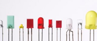
A diode is a radio element with two terminals. Some diodes look almost the same as resistors:
And some look a little different:
There are also SMD versions of diodes:
The terminals of the diode are called anode and cathode . Some people mistakenly call them “plus” and “minus”. This is not true. You can't say that.
In the diagrams the diode is designated as follows
It can only pass electric current from the anode to the cathode.
What is a diode
A diode is an electronic type of element on a board, which consists of several semiconductor layers and has different permeability and power, depending on the direction of the electric current. The electrode is divided into an anode and a cathode. In most cases, it is needed in order to carry out protective modulations with rectification and conversion of incoming electrical signals on the suppressor.
What does a diode consist of?
In our world there are substances that perfectly conduct electric current. This mainly includes metals, for example, silver, copper, aluminum, gold and so on. Such substances are called conductors. There are substances that conduct electricity very poorly - porcelain, plastics, glass, and so on. They are called dielectrics or insulators. Between conductors and dielectrics are semiconductors . These are mainly germanium and silicon.
Once germanium or silicon is mixed with a minute fraction of arsenic or indium, an N-type semiconductor is formed when mixed with arsenic; or a P-type semiconductor when mixed with indium.
Now if these two P and N type semiconductors are welded together, a PN junction is formed at their junction. This is the structure of a diode. That is, the diode consists of a PN junction.
diode structure
The P-type semiconductor in the diode is the anode, and the N-type semiconductor is the cathode.
Let's open the Soviet D226 diode and see what's inside it by grinding off part of the body on an emery wheel.
diode D226
This is the same PN junction
PN junction diode
Main conclusions
The options for checking a diode with a multimeter are quite simple and accessible even to non-professionals.
- Before testing, it is necessary to determine the type of semiconductor.
- For your home, it is more convenient to purchase a digital multimeter with more accurate measurements.
- The latest models of testers measure several parameters at once.
- When carrying out the test, it is necessary to ensure that the probes are correctly applied to the corresponding electrodes.
- The performance assessment is given on the basis of two parameters: the correspondence of the voltage value to the type of diodes for direct connection and zero value for reverse connection.
- You can check without desoldering the semiconductor.
The main thing is to correctly make all connections during the procedure and correctly interpret the data received. This will allow you to replace the component in time and solve the problem in the shortest possible time and at minimal cost.
Previous
LEDsHow to check the health of LEDs with a multimeter
Next
Lamps and lampsAre LED lamps harmful to human health: the benefits and harms of diode light
How to determine the anode and cathode of a diode
1) on some diodes the cathode is marked with a stripe that differs from the color of the body
2) you can check the diode with a multimeter and find out where its cathode is and where its anode is. At the same time, check its performance. This method is ironclad ;-). How to check a diode using a multimeter can be found in this article.
It is very easy to remember where the anode is and where the cathode is, if you remember the funnel for pouring liquids into the narrow necks of bottles. The funnel is very similar to the diode circuit. We pour it into the funnel, and the liquid flows very well, but if you turn it upside down, try pouring it through the narrow neck of the funnel ;-).
How to test different types of diodes with a tester - complete instructions
In the process of repairing household appliances or other electronic devices: monitor, printer, microwave, computer power supply or car generator (for example, Valeo, BOSCH or BPV), etc.
there is a need to check the integrity of the elements. We'll tell you in detail about testing diodes. Given the diversity of these radioelements, there is no uniform method for testing their performance. Accordingly, each class has its own testing method. Let's look at how to test a Schottky diode, photodiode, high frequency, bidirectional, etc.
As for testing devices, we will not consider exotic testing methods (for example, a battery and a light bulb), but will use a multimeter (even such a simple model as DT-830b will do) or a tester. Radio amateurs almost always have these devices at home. In some cases, you will need to assemble a simple circuit for testing. Let's start with classification.
Diode in DC circuit
As we have already said, a diode allows electric current to pass in only one direction. To show this, let's put together a simple diagram.
direct connection of the diode
Since our incandescent lamp is 12 Volt, therefore, we also set the value on the power supply to 12 V and assemble the entire electrical circuit according to the diagram above. As a result, our light bulb burns perfectly. This indicates that electric current is passing through the diode. In this case, the diode is said to be connected in the forward direction.
direct diode
Let's now change the leads of the diode. As a result, the diagram will take this form.
reverse diode switching
As you can see, the light bulb does not light up, since the diode does not allow electric current to pass through, that is, it blocks its passage, although the power source produces its honest 12 Volts.
reverse diode switching
What conclusion can be drawn from this? A diode conducts direct current in only one direction.
Checking the photodiode
In a simple test, the reverse and forward resistance of a radio element placed under a light source is measured, after which it is darkened and the procedure is repeated. For more accurate testing, you will need to take the current-voltage characteristic; this can be done using a simple circuit.
An example of a circuit for measuring current-voltage characteristics
To illuminate the photodiode during testing, you can use an incandescent lamp with a power of 60 W or more as a light source or bring the radio component to a chandelier.
Photodiodes sometimes have a characteristic defect, which manifests itself in the form of a chaotic change in current. To detect such a malfunction, it is necessary to connect the element under test as shown in the figure and measure the reverse current for a couple of minutes.
Testing for "creep"
If during testing the current level remains unchanged, then the photodiode can be considered working.
Testing without desoldering.
As practice shows, it is not always possible to test a diode without desoldering it when it is on the board, like other radio components (for example, a transistor, capacitor, thyristor, etc.). This is due to the fact that elements in the circuit may produce an error. Therefore, before checking the diode, it must be desoldered.
Today we can’t live without electronics. It is an integral part of any modern device or gadget. At the same time, all devices, sadly, cannot work forever and periodically break down. One of the fairly common causes of failure of a number of electrical appliances is the failure of an electrical element such as a diode.
You can check the serviceability of this component yourself at home. This article will tell you how to test a diode with a multimeter, as well as what these elements are and what the measuring device itself is.
Diode in AC circuit
For those who have forgotten what alternating current is, read this article. So, in order to consider the operation of a diode in an alternating current circuit, let's draw a diagram. Here we see a frequency generator G, a diode and two terminal blocks X1 and X2, from which we will take a signal using an oscilloscope.
My frequency generator looks like this.
frequency generator
We will take an oscillogram using a digital oscilloscope
The generator produces alternating sinusoidal voltage.
sine wave
What happens after the diode? We connect to terminals X1 and X2 and see this oscillogram.
AC voltage after diode
The diode cut out the bottom part of the sine wave, leaving only the top part.
What happens if we change the diode leads? The scheme will look like this.
alternating current after diode
What do we get at terminals X1 and X2? Let's look at the oscillogram.
alternating current after diode
Wow! The diode cut off only the positive part of the sine wave!
Checking the suppressor (TVS diode)
Protective diode, also known as limiting zener diode, suppressor and TVS diode. These elements come in two types: symmetrical and asymmetrical. The former are used in alternating current circuits, the latter - in direct current. If we briefly explain the principle of operation of such a diode, it is as follows:
An increase in input voltage causes a decrease in internal resistance. As a result, the current in the circuit increases, which causes the fuse to trip. The advantage of the device is its fast response, which allows it to absorb excess voltage and protect the device. Response speed is the main advantage of a protective (TVS) diode.
Now about the verification. It is no different from a regular diode. True, there is an exception - Zener diodes, which can also be attributed to the TVS family, but in essence they are a fast zener diode operating according to the “mechanism” of avalanche breakdown (Zener effect). But the performance check reverts to a regular dialing test. Creating triggering conditions leads to failure of the element. In other words, there is no way to check the protective functions of a TVS diode; it’s like checking a match (whether it’s good or not) by trying to light it.
Diode Characteristics
Let's look at the characteristics of the KD411AM diode. We look for its characteristics on the Internet, typing into the search “datasheet KD411AM”
To explain the parameters of the diode, we also need its current-voltage characteristic
1) Reverse maximum voltage Urev is the voltage of the diode that it can withstand when connected in the reverse direction, while current Irev will flow through it - the current strength when the diode is connected in reverse. When the reverse voltage in the diode is exceeded, a so-called avalanche breakdown occurs, as a result of which the current sharply increases, which can lead to complete thermal destruction of the diode. In our diode under study, this voltage is 700 Volts.
2) Maximum forward current Ipr is the maximum current that can flow through the diode in the forward direction. In our case it is 2 Amperes.
3) Maximum frequency Fd , which must not be exceeded. In our case, the maximum diode frequency will be 30 kHz. If the frequency is higher, our diode will not work correctly.
Diode. Part 1
Somehow I didn’t really paint this simple detail. Well, a diode and a diode. Nipple system. It lets you through in one direction, but doesn’t let you through in the other, which is easier. In principle, yes, but there are nuances. This article will be about them, and a little about the rough choice of this part.
▌Valve
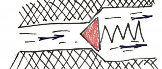
In a nutshell, in our sewer electrics for plumbers, the diode is a valve. Something like this:
And yes, it would be a big assumption to assume that the valve flows in one direction and not in the other. In fact, everything is somewhat more complicated. In fact, the valve has a certain elasticity of the spring, and so until the direct pressure overcomes this spring, there will be no flow, even in the forward direction.
This is equally true for a diode. The diode has such a parameter as voltage drop. For Schottky diodes it is about 0.2…0.4 volts, and for conventional diodes it is about 0.6…0.8 volts.
Three simple conclusions follow from this knowledge.
1) In order for current to flow through the diode, the voltage across the diode must be higher than its voltage drop.
2) No matter what current flows through the diode, there will always be a voltage across it approximately equal to its voltage drop (that’s why it’s called that way). Those. The diode resistance is nonlinear and decreases with increasing current.
3) By connecting a diode in series with the load, we will lose a voltage across the load equal to the voltage drop of the diode. Those. If you put a diode in a 4.5 volt battery to protect against polarity reversal, you will lose 0.7 volts from the batteries, which is quite significant. Your device will stop working much sooner than the batteries actually run out. And the batteries will not be completely drained. In this case, it is better to install a Schottky diode. It has a lower drop than a simple one (but it has its own jokes). Or better yet, a field-effect transistor.
Let there be a graph too:
This is the current-voltage characteristic of the diode. Which clearly shows that it opens at approximately 0.7 volts. Before this, the current is practically zero. And then it grows parabolically upward with increasing voltage. The resistor's current-voltage characteristic would be linear in direct accordance with Ohm's law. And it’s not that the diode does not pass into the return line, but the current there is very insignificant, fractions of a milliampere. But after a certain voltage, the diode suddenly breaks through and it begins to open, the voltage drop is set somewhere at the level of the reverse voltage limit, and then it completely burns out. After all, an increase in current and a large voltage drop across the diode mean large thermal losses (P=U*I). But the diode is not designed for them. So it usually burns out after a breakdown. But if you limit the current or exposure time so that the thermal power does not exceed the design value, then the electrical breakdown is reversible. But this only applies to ordinary diodes, not Schottky ones. Those break through immediately and completely.
And here is the real characteristics of the Vishay 1N4001 diode
Direct current-voltage characteristic, one quadrant is shown, working. It starts somewhere at 0.6 volts. At the same time, the current there is negligible. And then, with increasing voltage, the diode begins to open sharply. At 0.8 volts the current is already 0.2A, at 1 volt it is already 2.5A and so on until it burns out
