Overload protection circuit
US Patent 2004008463 (2004) describes an overload protection circuit. The functional diagram of the device is shown in Fig. 1. It includes an output device 12 (a differential pair of transistors), the output of which 14 can be either high or low potential, depending on the conditions at the input contact 16.
Rice. 1. Functional circuit of overcurrent protection, patent.
The control unit 18, depending on the signal at input 16, provides the necessary signals on buses 20 and 22 for output device 12. From output device 12, buses 19 and 21 come out, which reflect the state of output device 12.
A sensor 24 is connected to these buses, which determines the output current and transmits measurement data via buses 23 and 25 to the control unit 18, which, in turn, changes the signals on buses 20 and 22, adjusting the current of the output device. Delay lines 24 and 26 are necessary for “soft” switching on of the output device.
Protective power control device in a car
Power line control with wide voltage monitoring hysteresis - diagram
The solution shown in the figure above protects electronics that are sensitive to transient conditions - dips, surges and overcurrents that occur in the car's power source.
The LTC2966 monitors both reverse voltage and forward voltage that is too low or too high. Control thresholds and hysteresis levels are adjusted by resistor circuits on the INH and INL pins and voltages on the RS1 and RS2 pins. OUTA is the output of the UV comparator and OUTB is the output of the OV comparator. The polarity of these outputs can be selected to be reverse or normal to the inputs using the PSA and PSB pins. In the figure they are configured as non-inverting. The OUTA and OUTB pins from the LTC2966 are connected to the REF pin of the LTC2966 and are fed directly to the UV and OV pins of the LTC4368.
The LTC4368 provides reverse current and overcurrent protection. The size of the current sensing resistor R11 determines the permissible levels of reverse current and overload. The LTC4368 decides whether to turn on the load based on the status of its overcurrent comparators as well as monitoring information from the LTC2966. Contacts UV, OV and SENSE (overcurrent) are precisely involved in the decision-making process. If these conditions are met for all three pins, the GATE pin will be pulled up above VOUT and the load will be connected to the power supply via the dual N-channel MOSFET in the power line. If any of the three pins is at an incorrect voltage level, the GATE pin drops below VOUT and the load is de-energized.
A car powered directly from the battery is subject to large voltage fluctuations when starting and stopping the engine. In this protection solution, voltage control thresholds are based on rated operating voltages and are expected during vehicle startup or circuit discharge while protecting downstream electronics.
Start-up transients are generated when the ignition is energized to start the vehicle. In this enablement, Channel A of the LTC2966 is configured to detect a transient state at startup. Transients during energy reset occur when the engine is turned off. Large amplitude surges occur at the battery terminal when the current in the vehicle line suddenly stops. In this case, the LTC2966 is configured to detect the power reset transient when the engine stops.
Vout vs Vin chart
The graph shows the input voltages during operation. Engine start (channel A) is detected such that it is activated when the voltage drops below 7 V and is reactivated by voltage above 10 V. The second protection (channel B), designed to detect engine stalling, is configured to activate when the voltage exceeds 18 V, and must turn off when it drops below 15 V. These voltages arise directly from the machine's start-stop curve, determined by the manufacturer's standards.
If necessary, you can select other voltage ranges, which are easily adjusted by changing the resistance values of the voltage divider elements on the INH and INL lines of the LTC2966 chip.
Semiconductor configuration for current limiting
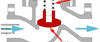
German Patent 19717614 (2002) describes a semiconductor configuration for current limiting. Figure 2 shows a diagram of connecting an electrical consumer 12 to a two-wire network (phase R and ground Mp).
Rice. 2. Semiconductor configuration for current limiting, patent.
An electronic current limiter 13 is installed in the line (a special semiconductor design described in the patent). Its terminals 13A and 13B are connected to device 16, which is triggered when a predetermined voltage is exceeded. When device 16 is triggered, line 17 is broken by relay contacts 14.
Circuit operation
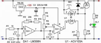
The scheme works as follows. For example, with a load current of 3A, a voltage of 0.01 x 3 = 0.03V will be released at the current sensor. The output of amplifier DA1.1 will have a voltage equal to 0.03V x 100 = 3V. If in this case, at input 2 of DA1.2 there is a reference voltage set by resistor R6, less than three volts, then at the output of comparator 1 a voltage will appear close to the supply voltage of the op-amp, i.e. five volts. As a result, the optocoupler LED will light up. The optocoupler thyristor will open and bridge the gate of the field-effect transistor with its source. The transistor will turn off and turn off the load. You can return the circuit to its original state with the SB1 button or by turning the power supply off and on again.
The disadvantage of the circuit is the unipolar power supply of the operational amplifier; therefore, at low values of the voltage drop across the current sensor, a large nonlinearity of the gain of the op-amp DA1.1 occurs.
Download article
Telephone line current limiter
A telephone line current limiter is described in French patent 2804550 (2001). The current limiter (Fig. 3) is connected in series to two telephone lines 1 and 2. In each line, the limiter contains resistors (R1 and R2), capacitors (C1 and C2) and bidirectional diodes (D1 and D2) connected in parallel.
Rice. 3. Current limiter in a telephone line, patent.
Do-it-yourself short-circuit protection for the power supply
Sometimes when setting up homemade electronic devices, a short circuit occurs, which can cause the power supply to fail. Therefore, the power supply must have reliable short circuit protection, capable of quickly disconnecting the shorted load at the right time and protecting the power supply from damage.
This figure shows a diagram of a simple device designed to reliably protect a power supply from short circuits.
Power supply short circuit protection circuit
The operating principle of relay protection is quite simple. When voltage is applied to the circuit in standby mode, the red LED lights up. After pressing the S1 button, current flows to the relay winding, the contacts switch and block the relay winding, thus the circuit goes into operating mode, this is indicated by the green LED lighting up, and current flows to the load. If a short circuit occurs, the voltage on the relay winding disappears, its contacts open, the load is automatically switched off, and the red LED lights up, signaling that the relay protection has activated.
The circuit is designed to work with a constant output voltage from 8 to 15 volts, so it will work perfectly with a charger from a computer power supply, as well as with any other transformer or switching power supplies with an output voltage in the specified range.
This circuit can be considered universal, because it can be easily converted to any voltage; you just need to replace the relay for the voltage you need, and of course, if necessary, select resistors R1 and R2 to match the LEDs installed in the circuit.
Printed circuit board for protecting the power supply from short circuits.
Power supply short circuit protection circuit board
Let's see how the finished short circuit protection device for the power supply works. In the standby state after power is applied, the red LED lights up, the load is turned off.
Press the button and the device will go into operating mode.
The green LED lit up, signaling that power was supplied to the load; I use an ordinary 12 volt light bulb as the load.
Using a screwdriver, I close the central contact with the base of the light bulb, a short circuit is obtained, the short circuit protection is instantly activated, the load is turned off, the red LED lights up with its light, indicating a short circuit.
Radio components for assembly
- Relay SRD-12VDC-SL-C, you can use a similar one for a different voltage
- Resistors R1, R2 1K resistance select for each LED
- LEDs 5 mm 2 pcs. red and green
- Any button without locking with normally open contacts
Friends, I wish you good luck and good mood! See you in new articles!
I recommend watching a video on how to make short circuit protection for a power supply
Overload protection
Overload protection is described in UK patent 2336046 (1999). Telephone set 20 (Fig. 4) is connected to line 11, 12. When the current exceeds the norm, the transistor cascade 40 is turned on, and through it the bypass circuit 30, in which the transistor 110 takes over the excess current. Thus, excess current bypasses the telephone set.
Rice. 4. Telephone line overload protection, patent.
Power supply parts
Transistor VT2 can be changed to KT315B - KT315E. Transistor VT1 can be replaced with any one from the KT827, KT829 series. Diodes VD2 - VD4 can be used KD522B. Resistance R13 can be assembled from three parallel-connected MLT-1 resistors with a resistance of 1 Ohm each. Zener diode VD1 is any with a stabilization voltage of 7...8 volts and a current of 3 to 8 mA. Containers SZ, C4 are arbitrary film or ceramic. Electrolytic capacitors: C1 - K50-18 or similar foreign, others - grade K50-35. Button SA1 without fixation.
Source: Radio, 9/2006
Electrical plug
International patent PCT 9848504 (1998) describes an electrical plug. This is a low-power plug that has a built-in protection circuit. The plug diagram is shown in Fig. 5. The mains wires are marked 10 and 12, the load outputs of the plug are marked 20 and 22.
Rice. 5. Plug for low-power load, which has a built-in protection circuit, patented.
The plug includes fuses 14 and 16 and an integrated circuit 50. A thermistor 52 and a special diode (not designated) are connected in series between the input and output contacts. This diode is called a "solid-state rectifying fuse".
If the diode current exceeds the rated current, it operates as a fuse. In addition, a regular diode is included in the circuit. The diagram is designed to include Christmas tree garlands.
Let's sum it up
The use of specialized devices can simplify the implementation of safety schemes in cars. With minimal additional circuitry, the LTC2966 and LTC4368-2 have been combined to provide accurate, reliable, and versatile surge protection. And the flexibility of these devices allows them to be configured for use in many types of vehicle on-board networks. In the simplest case, you can use this homemade protection scheme, although of course expensive automotive equipment and an on-board computer require a more professional approach.