Call, Miscellaneous
Applied science does not stand still. Thanks to this, our life becomes comfortable and safe. This is how new devices and gadgets appear in everyday life, and old ones are improved. They become compact, versatile and quickly get rid of wires. The situation is similar with doorbells. Nowadays you won’t surprise anyone with a call with a lot of melodies, good sound quality or imitating a person’s voice.
But the wireless radio call is a new product on the market. However, its popularity is only growing every day. This is due, first of all, to the fact that it is easy to install and does not require laying wires or drilling into walls. This is important when it is installed on a vestibule door or on the gate of a private house.
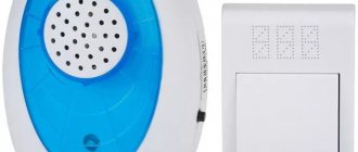
Wireless doorbell
So what is the secret of such a unique device. As they say, everything ingenious is simple. It is enough to look under its body to be convinced of this.
Wireless call schemes
Radio calls differ from each other in their set of functions, range or power source. They are similar in one thing - they have a signal receiver and transmitter. The source is a button, and the receiver is a device with a music chip, antenna and speaker. Let's take a closer look at how the wireless doorbell circuit is fundamentally expressed.
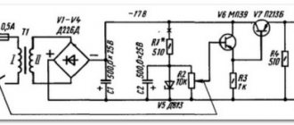
Approximate view of transmitter microcircuits
As can be seen in the diagram, the transmitter consists of a high-frequency generator, an amplifier-converter, three transistors and a power source. A 12 volt battery is used as a power source. The signal transmission frequency to the receiver is 433 MHz. There is no antenna as such here. It consists of two circuits that are connected in parallel. Thus, a simple microcircuit allows you to transmit a signal over 50 meters or more.
General view of the receiver chips
The receiver device is quite simple. It is based on one transistor. From the transmitter the signal goes to the detector. He receives it and sends it to the amplifier. The signal is then sent to the sound chip. The future signal that a person will hear is generated on this chip. Also thanks to him, they change the melodies, choose the sound volume, and so on. After the signal reaches the chip, it goes to the sound amplifier and then to the speaker.
Most Chinese-made call transmitter and receiver microcircuits are designed according to this principle.
For comparison, consider the circuits of Chinese wired doorbells. The main difference is the presence of antennas and the method of transmitting the signal from the transmitter to the receiver.
Wired Chinese call diagram
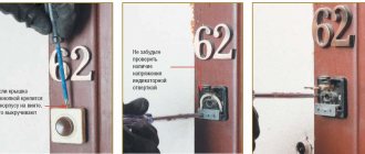
Connecting a doorbell
Such designs are the most common and well known. Among them, electromechanical models first appeared, which began to be installed on the houses of noble people from the second half of the 18th century. They continue to operate with minor improvements to this day.
After the start of industrial development of semiconductor elements, doorbells on an electronic circuit began to be produced
After the industrial development of semiconductor elements began, doorbells based on electronic circuits began to be produced. They have the same type of bell ringing replaced with more varied and melodic sounds, which can be adjusted in duration, volume and other parameters. Two wires come out of the decorative plastic case, which are connected to the power supply circuit of the household network.
On the back of the case are located:
On such calls, they used to indicate not only the network parameters (≈220V, 50Hz), but also the type of button - 250 volts, no lower. This is dictated by safety regulations. Inside the case there is a speaker and a getinaks board with electronic components.
Typical doorbell connection diagram
Electromechanical and electronic wired models are connected to the power circuit according to the same principle: when voltage is applied to the input terminals, sound begins, and when turned off, it stops. To do this, the network zero is connected through the terminal of the distribution box to one bell wire, and the phase is also sent to the second terminal, but with an additional connection to the contacts of a self-resetting button through a separate terminal.
Thus, in the electrical bell connection diagram, the junction box connects three cables from:
Electromechanical and electronic wired models are connected to the power circuit according to the same principle
The cable connecting the button to the distribution box passes through the wall into which the door block is mounted. Typically, such a connection diagram is carried out by builders during the construction of a building and is included in the work project. If you are building it yourself, you will have to trench the walls for internal hidden wiring.
The current loads created by the bell are small. In addition, they last for a short time. Therefore, the thermal effect on the wiring is insignificant, which allows the use of a reduced cross-section of wires. Most often, 1.5 mm square is chosen not according to thermal load, but according to mechanical strength.
Depending on the needs of the apartment residents, the standard layout may change. Sometimes, when an apartment is located in a common vestibule that is locked, it becomes necessary to install bell buttons on the vestibule and entrance doors so that a guest from the entrance and a neighbor in the apartment can conveniently call the owner.
All the considered schemes work in buildings equipped with electrical wiring installed using the TN-C system. In modern conditions, there is a transition to the TN-S or TN-CS system. They add an additional protective PE conductor, which connects the metal housings of all devices to the ground through a junction box.
Homemade wireless bell
Let's consider one of the homemade microcircuits of a wireless analogue of such a device. In the basic principle of operation they are similar, but there are some differences. The main difference is the frequency at which the signal is transmitted from the transmitter to the receiving device - 87.9 MHz. The device itself consists of the following main modules:
- Control circuits,
- sound chip,
- transmitter,
- Power supply.
Let's look at each element of the circuit in more detail.
Diagram of a homemade radio doorbell.
The device is controlled using the S1 button. Essentially, it starts the music chip and timer of the transmitter. When it is pressed, voltage flows to pins 6 and 13. There is also a microcircuit with resistor R2 and two diodes VD1 and VD2. It limits the upper voltage value at pins 6 and 13. This is necessary since the USM and K561 microcircuits differ in their logical level. The control device itself is based on the D1 chip. It plays the role of a timer that turns on the transmitter for a few seconds after the S1 button is pressed.
Single positive pulses are generated through elements D1.1 and D1.2. Their duration is directly related to the time constant in the C1-R4 circuit (taking into account the values indicated in the diagram, we can say that the duration of the pulses is about twenty seconds). The pulse changes polarity, hitting the inverter D1.3, and then goes to the VT1 switch. The power source is transformerless, and the installed capacitor C5 dampens excess voltage.
Important! In this circuit, polar capacitors are used of the electrolytic type, C11 and C12 are ceramic, and the rest are of any kind. It is necessary that all capacitors have a voltage of at least 16V, and for C5 - at least 300V. Coils L1 and L2 are wrapped with thin wire: the first - 6 turns, the second - two. Both are frameless and have an internal diameter of seven millimeters.
The UMS8-08 microcircuit is used for the sound chip. It reproduces 8 different sounds embedded in it. The selection of melodies is carried out by flipping through S1. If you send output pulses from chip D2 through transistor switch VT2 to transformer T1 with capacitor C10, and then to the speaker, the sound of the signal will be soft and pleasant to the ear (high and harsh sounds will disappear).
A piece of wire is used as an antenna. A length of no more than a meter will be sufficient. With such an antenna, the device transmits a signal from the transmitter to the receiver over a distance of up to one hundred meters.
Now you need to configure the device. The first step is to check the power source. Next, check that the sound chip is working correctly. If everything works, then proceed to setting up the transmitter. For a while, the wiring closes VT1 and the emitter. The receiver itself is installed at the frequency indicated above. Using settings C11 and C12, we achieve reliable reception at maximum range. Thanks to resistor R8, we set modulation for better sounding of the receiver. Then the jumper is removed and the timer is set on D1. To do this, briefly press button S1. In this case, the transmitting device turns on and operates for several seconds. If this time period is too small or, conversely, too long, then it is changed by selecting R4 and C1.
Thus, having minimal knowledge and purchasing everything you need at the nearest radio store, you can make a reliable call yourself.
No less interesting information about the types of electric bells
Electronic call for a telephone on a chip
The electrical circuit of the electronic bell is shown in the figure. A constant supply voltage in the range of 11-29 V is supplied to the output of the internal power supply with hysteresis (pin 1). The useful output current of the microcircuits is up to 35 mA at an output voltage of up to 17 V, which allows you to load the microcircuit with low-power light and sound indicators without an additional current-amplifying cascade, as well as convert the output signal to control actuators. The load must have a resistance of at least 150 Ohms.
The microcircuit contains two built-in oscillators 34 and an output amplifier. One of the generators with an RC chain connected to pins 3 and 4 produces pulses with a frequency of about 10 Hz. This signal is the control signal for another generator, the corresponding RC elements of which are connected to pins b and 7 of the microcircuit. The resulting amplified signal from the output of the microcircuit (the pin is applied to the load. The voltage to turn on the low-frequency generator is applied to pin 2. The switching on of this generator directly depends on the voltage value at pin 2, so you can control the operation of the entire node by changing the voltage amplitude. Thus, based on DBL5001 and DBL5002 microcircuits and similar ones can be used to design parametric alarms with thermal and photo sensors, watchdog devices, pulse generators and other simple multifunctional devices.And the electrical parameters allow these microcircuits to be used in a wide variety of devices, despite the fact that they were specially designed for telephony.
In the absence of a call signal (and the phone is on-hook), the constant voltage in the telephone line is approximately 60 V. Capacitor C1 does not pass the direct voltage component, therefore, at pins 1 and 4 of the DA1 microcircuit, the supply voltage is zero. The sound capsule is not active. When you pick up the handset, the DC voltage in the telephone line drops to 3-6 V. When making a call from the telephone line, an alternating voltage (about 60 V) passes through capacitor C1, limiting resistor R1, is rectified by bridge diodes VD1-VD4 and goes to the DA1 chip – pins 1 and 4. Pin 4 is used to power the internal output amplifier of the microcircuit, which in this case is turned on simultaneously with the power supply. Oxide capacitor C2 smoothes out voltage ripples. The capacity of this capacitor was selected experimentally. Increasing it in this case is not recommended, otherwise, due to the accumulated charge on the C1 plates and the low current consumption of the DA1 microcircuit, the generator will work and the HA1 capsule will emit signal 34 not only during intermittent phone calls, but constantly, that is, while the subscriber receives call. Through limiting resistor R2, a constant voltage of 10-12 V is supplied to the control input of the low-frequency oscillation generator, and it, in turn, starts the second generator, the oscillation frequency of which is determined by the elements R4C4. In this case, this frequency is about 800 Hz. The sound piezoelectric capsule HA1 turns on and emits a signal 34. The circuit uses a sound capsule HA1 type NSM1206X. Instead, you can use any other piezoelectric or dynamic capsule with a resistance of at least 150 Ohms. Instead of foreign microcircuits DBL5001 and DBL5002, domestic microcircuits KR1436AP1, EKR1436AP1 can be used in the circuit without any changes. These microcircuits can be used to repair imported telephones in which the call is implemented on DBL5001 and DBL5002 microcircuits. All fixed resistors in the circuit are of the MLT-0.25 type. Oxide capacitors - type K50-29 or similar. Non-polar capacitor C4 - type KMB with group TKE N70 or similar. Capacitor C1 - type MBM, MBGO, K73-10 or similar for an operating voltage of at least 100 V. Diodes VD1-VD4 can be used type KD103 or KD105 with any letter index. The device does not require adjustment. The DA1 chip receives power directly from the telephone line (TL). Connection to the TL is made through a connector, for example RP2-5. The polarity of the connection in this case is not important. Kashkarov A.P.
File:
Tweet Like
- Previous entry: Complete protection device for lighting lamps
- Next post: Heterodyne resonance indicator
- What is the difference between current and voltage? (2)
- Current and Voltage Relationship (0)
- MOTORCYCLE SECURITY ALARM (0)
- POWER SUPPLY FOR CAR RADIO (0)
- BATTERY ELECTRICAL ISOLATION DEVICE (0)
- LITHIUM-NON CELL CHARGER CHARGER CONTROLLER (0)
- MULTIPLE LITHIUM CELL CHARGER (0)
Related posts:
Ringing from unnecessary devices
If you have an old phone or a broken computer mouse that is beyond repair, these will come in handy if you decide to make your own wireless doorbell. Consider the option of making a similar device from a mouse:
- All internals are removed from the case except the contact buttons.
- On the board, two keys are connected to the bell device, and the remaining parts are removed.
- The wheel is cut in half and one part is glued back.
- On the remote control board, a twisted pair is soldered to the sound button. It connects the button to the mouse keys.
- Solder the remaining ends to the key contacts - one to the outermost one, the second to any of the remaining two.
- The last contact of the three is connected by a wire to the opposite one. This way both buttons will work.
The original call is ready.
Voted over 280 times, average rating 5
Comments
Vladimir 03/28/201721:44 Cheap and effective. We need to adopt it!
Grade
VLAD 01/26/202015:41 Coils L1 and L2 are being wound - they are being wound!
Grade
Add a comment Cancel reply
We recommend reading
Bell, Miscellaneous What is a video doorbell and do you need it? Today, the question of ensuring the safety of one’s...
Call, Miscellaneous Wireless call: how to choose and install? In the age of modern technology, new gadgets are appearing...
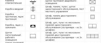
Bell, Miscellaneous How is a bell symbolized on an electrical diagram? Before we tell you how the bell is indicated on any electric...
Bell, Miscellaneous Types and main characteristics of wireless doorbells for the deaf Wireless doorbells for the deaf are the optimal solution to the problem...
Installation
Installing wireless doorbells is extremely simple, which is the main advantage of such devices. It is necessary to install batteries inside the calling panel and subscriber unit (depending on the version) and secure them to the door or wall using double-sided adhesive tape or 1-2 screws. This completes the installation of the device and the product is ready for use. If the subscriber unit operates on AC power, it must first be plugged into an existing outlet.
The widespread use of wireless doorbells has led to a large number of reviews about specific models on the websites of their sellers.
Most of the positive reviews are devoted to fairly expensive models, characterized by high quality workmanship and exquisite design. Negative reviews are devoted to low-grade Chinese crafts that do not deserve any attention.
Device
Calls are available wireless and electric. To understand their structure, you need to consider each type separately.
Wired
This type of device can be divided into two parts: internal and external. The external one, in the form of a button, is located outside the living space and is used by visitors. A device with a speaker that receives a signal triggered by pressing a button is located in the apartment itself.
For the system to work, it is connected to the electrical network. The working process occurs by closing the circuit, when the visitor presses the button, the circuit is closed and the owner hears a bell. The speaker can be moved to any room, but to do this you will need to lay an electrical wire throughout the apartment.
Wireless
The action of a wireless call occurs due to radio waves, and not electric current, and this is its difference from the previous version. In the device, a radio signal from a button, that is, a transmitter, goes to a device inside the apartment, the so-called receiver. Signal transmission occurs using mini-antennas built into the receiver and transmitter, or microcircuits.
The bell button can be located at a distance of up to 150 m from the receiving device, which is very convenient to use for equipping private homes. In this case, the receiver does not have to be installed at the front door itself, as is the case with the electric model; it can take its place in any of the rooms.