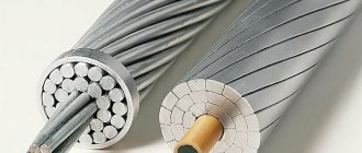
Advantages of lines based on SIP
The use of SIP wires allows you to avoid short circuits, even when they come into contact with grounded structures. There is no need to re-install to replace insulators, adjust sagging, and it becomes possible to carry out repair work under voltage.
When installed over the air, high electrical safety is ensured by eliminating the risk of wires coming into contact with conductive objects, eliminating ground faults.
SIP-based lines are structurally simple, and with the use of modern tools and fittings they have high installation readiness. They also have low inductive resistance, which reduces energy losses.
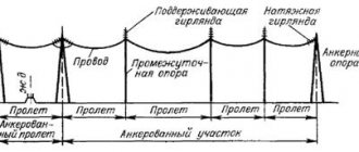
Installation of overhead power lines
Installation of 10 kV overhead lines and other voltages is significantly cheaper than laying a similar cable in the ground. Therefore, as a rule, the first option is chosen. Underground cable laying is usually practiced in urban areas due to various restrictions. All these issues are resolved before the design phase begins. If necessary, we install aerial cable lines.
The choice of method for laying lines is determined based on the results of engineering surveys, taking into account the terrain, soil types, the presence of other infrastructure along the route and other circumstances. For example, installation of a 10 kV power line involves installing supports at a distance between them of no more than 60 meters. There are many such requirements when installing overhead lines, and they must be taken into account in advance.
Installation features
Before installation work begins, it is necessary to prepare the route: cut down trees, trim large leaves, remove obstacles.
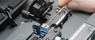
When rolling out the wire, measures are taken to maintain its integrity, prevent it from coming into contact with concrete and metal structures, and control the installation forces to avoid overtightening the wire. Installation work is carried out at an ambient temperature not lower than - 20°C and in strict accordance with the design documentation, which has been approved by the regulatory authorities.
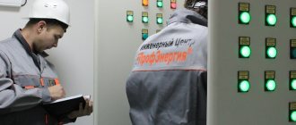
Works and their frequency
According to the approved schedule, drawn up taking into account structural features, climate and other factors, routine inspections of overhead power lines are carried out. During the inspection, all defects and damage are recorded in order to eliminate them during repair work.
Typically, inspections are carried out once a year, but during operation, the need for unscheduled repairs may arise.
In case of critical deterioration of the structure, we are talking about major repairs - replacement of supports, wires, work aimed at reconstructing lines.
There are cases when repair work is impractical, then dismantling and construction of a new power line is carried out.
Installation of support and bushing insulators 6-10 kV
Insulators in switchgears and substations are designed for mechanical fastening and electrical insulation of busbars and live parts of high-voltage devices. According to the method of installation and purpose, insulators are divided into substation and equipment, support, walk-through and suspended (the latter are also called linear). In addition, insulators are manufactured for indoor and outdoor installations.
In switchgears for voltages of 6–10 kV, support insulators of the IO series and bushings of the IP series are used. The symbol for an insulator, for example IO-6-375, is deciphered as follows: support insulator, for internal installation at a rated voltage of 6 kV and a minimum breaking load in bending of 3.75 kN. In addition, the designation may indicate the shape of the flange: oval (s), round (cr) and square (sq).
The support insulator consists of three parts: a porcelain hollow body, a glazed metal flange and a cap. The flange is used to fasten the insulator with one, two or four bolts to the base, and the cap is used to fasten the tires with bolts through a threaded hole in the cap. The porcelain hollow body is an insulating part. The metal parts are connected to the porcelain with a cement bond. Flanges are made of non-magnetic materials (cast iron, silumin). Porcelain and epoxy insulators are used.
Before installation in place, insulators are inspected and rejected. Each insulator is checked for cracks, chips and other mechanical damage. Broken edges with a total area of no more than 1 cm2 are allowed, but well sanded and covered with two layers of bakelite varnish. Light scratches on porcelain are also covered with bakelite varnish. The surface of the porcelain should be completely covered with glaze without any traces of putty. If the putty remains, it is cleaned with wooden spatulas. It is not allowed to clean with a steel knife or other steel objects.
Check the condition of the metal reinforcement of the insulators and the strength of the reinforcement. The putty layer must be uniform around the entire circumference of the reinforcement, and on insulators for internal installation, the reinforcement seam is varnished. Rust is removed with a rag soaked in kerosene, burrs are removed with a file to avoid injury to your hands during installation.
Installation of support insulators consists of their installation, alignment and fastening, connecting the flanges to the grounding loop and painting the heads and flanges. Insulators mounted with flanges directly on grounded metal structures are not additionally grounded.
Support insulators for laying busbars over them are mounted mainly on metal structures in workshops and are delivered to the installation site in the form of blocks, often with busbars already laid. The blocks are attached to building structures with nuts and studs embedded at the first stage of installation or welded to metal parts embedded in building structures.
When installing support insulators, comply with the following SNiP requirements:
- the centers of the heads (cast iron caps) of the insulators must coincide with the longitudinal and transverse axes of the markings;
- the planes of the insulator caps of each set (of 3 pieces), as well as this section or chamber, must be located at the same level (tolerance ± 2 mm);
- the distances between the axes of insulators of different phases, as well as from the axis of the insulators to grounded structures and the distances between individual insulators of the same phase (along the phase axis) must correspond to the design (tolerance ±5 mm);
- when installed on plastered walls (or ceilings), the insulator flange should not be recessed;
- the grounding bolts must be located on the side of the grounding line;
- gaskets under the flanges of insulators should not protrude beyond their limits;
- The insulators must be secured so that they can be replaced without cutting the busbar.
The installation of insulators for busbars is carried out in the following sequence: first, the outer insulators are installed and a cord is pulled along the centers of their heads, then the remaining insulators are installed along the cord and leveled in height, using spacers made of felting felt or cardboard, or sheet steel (when installed on metal structures). After final alignment in vertical, horizontal or inclined planes (the oval holes of the insulators and their fastening on double angles make it possible to adjust the distance between the insulators), the fastening bolts or studs are tightened with nuts.
To protect the insulators from damage during further work on the installation of the switchgear and finishing work, after final installation they are wrapped in roofing felt, cardboard or paper and tied with twine. If necessary, porcelain insulators are protected with a screen or asbestos from splashes of hot metal and high temperatures.
The bushing consists of a porcelain body with a hole for the passage of the conductive busbar. In the middle part it is reinforced with a cast iron flange with holes for bolting. The ends of the body are closed with reinforced caps - holders. Insulators of the P series for rated currents up to 2000 A are manufactured with an aluminum conductive busbar, which is secured with washers installed in the internal cavity of the insulators. The symbol for a bushing insulator, for example P-10/400-750, is deciphered as follows: bushing, porcelain, reinforced for indoor installation, for a rated voltage of 10 kV and a current of 400 A and a minimum breaking load of 7.5 kN. When checking and rejecting, bushings are subject to the same requirements as support ones. In bushings, the dimensions of the conductive rod and the absence of taper in it, the presence of nuts and centering washers are additionally checked.
In addition to the same requirements as for support insulators, installation of bushings requires additional requirements, depending on the presence of a conductive rod and the shape of the flange. Most often, bushings are installed on asbestos-cement or steel slabs. In bushing insulators with a rated current of 1000 A and above, steel plates are made of two halves, which are connected by strips of non-magnetic or low-magnetic material, maintaining a gap of 5-6 mm between these halves along the entire length. When installing such insulators on reinforced concrete slabs, the steel reinforcement of the latter is made so that it does not form a closed magnetic circuit around the individual phases. If these conditions are not met, steel plates and reinforcement will be heated by currents induced in them.
Plates with bushing insulators are installed in the openings left in the building part and are aligned in the horizontal and vertical planes with a level and a lath. The deviation of the slab symmetry axes from the design dimensions should not exceed ±2 mm. The bushings are placed on the slab, secured without tightening with bolts and nuts and carefully checked for level and plumb. The main vertical axes of the insulators must be in the same plane or located symmetrically with respect to the nearest elements of the installation, with which they will subsequently be connected by busbars. The deviation of the axes of the support and bushing insulators of each phase, as well as the axes of individual insulators from the position provided for by the design, is allowed no more than ±5 mm. After alignment, the bushings are secured to the slab, tightening the coupling bolts with nuts.
During the final finishing of the switchgear, the insulator fittings, both support and bushing, are painted with black enamel paint. The places where the flanges are connected to the grounding are not painted.
Issues covered
- What is the purpose of support and bushing insulators?
- The design of support and bushing insulators is described.
- What defects of support and bushing insulators serve as the basis for their rejection before installation?
- Describes methods for installing bushings in wall openings.
12860
Bookmarks
Comment
Comments 0
No one has commented on this page yet.
Write a comment
Repair work
The most common support defects corrected are:
- their bearing;
- restoration of waterproofing;
- elimination of sinks and cracks on pillars;
- applying anti-corrosion coating to metal supports, etc.
Repairs of overhead power line wires, adjustment of sag, cleaning of insulators and clearing of power line routes are also carried out.
This is not all the work carried out; ELEKOM specialists also carry out other repair activities, individually compiling a list of repair work in each specific case.
Support foundations.
Metal supports are installed on reinforced concrete foundations (footboards) or piles. The pits for the foundations of metal supports are excavated using excavators. Reinforced concrete piles are driven into the ground using a vibration-impact method. The depth of foundations or piles must correspond to the overhead line design.
Simultaneously with the construction of the foundations, the installation of grounding devices is carried out - artificial vertical and horizontal grounding conductors are installed. Reinforced concrete foundations of supports are used directly as natural grounding conductors. The upper parts of reinforced concrete foundations are leveled horizontally and a rigid template is installed on them, corresponding to the dimensions of the lower part of the metal support. After this, the pits are backfilled with layer-by-layer soil compaction. The template is removed after filling the pits. Reinforced concrete and wooden supports are installed without foundations. Excavation pits for wooden and reinforced concrete supports are developed with special drilling machines. The diameter of the pit must exceed the lower diameter (size) of the support column by 5... 10 cm. The depth of the pits must correspond to the overhead line design.