Repair of overhead power lines. Volume and frequency.
To regularly repair and maintain overhead power lines in proper condition, a special schedule is used, according to which the power lines are temporarily disconnected.
The frequency of routine repairs is at least 1 year. During routine repairs, supports are straightened and repaired, overgrown vegetation is cut down, tubular arresters are checked, individual sections of the network are re-strung, and damaged insulators are replaced. The frequency of major repairs of overhead power lines is 10 years. Wire repair
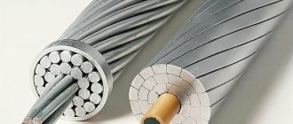
If the wires are insignificantly damaged (out of 19 wires, 3-5 are damaged), a bandage or repair sleeve is applied to the twisted wires. In this case, cutting out part of the wire is not performed. If the damage to a section of the wire is more significant, such a section is replaced, and the new wire has a lay direction similar to the one being repaired. The length of the insert is determined by the cross-section of the wire and is 5-10 m.
Adjusting wire sag
Such work is carried out by cutting or inserting part of the wire. Pre-measuring work is carried out and calculations are made. Next, the voltage is turned off, the wire being repaired is disconnected and lowered to the ground using anchor supports. The wire is cut, cut (inserted), and then installed in place. If the size of the cut or insert does not exceed 0.6 m, then the sag adjustment is usually carried out by changing the tension of the wire at the points of attachment to the anchor supports.
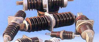
Replacing and cleaning insulators
Insulators can be cleaned when the voltage is turned off by wiping the line manually or when the line is running under voltage by washing the insulators with a stream of water. For such work, a telescopic tower is usually used, on which a stand with a water supply barrel is installed. Water is transported in a tank and supplied under pressure into the barrel by specially trained specialists.
Insulators can be replaced either with or without lowering the wire. If the mass of the wire is small, then it is not lowered, and a telescopic tower is used as auxiliary equipment.
Repair of supports
Over time, the supports gradually shift and deviate from the vertical position. If they are not repaired in a timely manner, the angle of inclination may increase uncontrollably, which will ultimately lead to the support falling. To restore the correct position of the wooden supports, a winch is used, after which the soil around the support is compacted. When straightening reinforced concrete supports, a telescopic tower is used.
Repair of overhead power line supports
The list of services for maintaining the electrical power supply system at the facility includes timely repair of overhead power line supports. The stability of the electricity supply to the facility and the efficiency of its operation depend on the speed and quality of the tasks performed.
If a power line breaks down, emergency network diagnostics and emergency repairs are carried out. Also, repair work can be of a planned nature: they provide for the preliminary elimination of faults that may subsequently lead to the failure of a section of the line.
In what cases is repair of overhead power line supports necessary?
The process of repairing power line supports includes a preliminary inspection of objects, checking the integrity of the above-ground and (if necessary) underground parts of the structures.
Pole repairs are carried out when the following types of violations are detected:
- concrete chipping and weathering in damaged areas;
- longitudinal and transverse cracks;
- change in concrete strength (measured by hammer tapping using calibration curve data);
- through holes with spalls to the post reinforcement;
- corrosion of concrete and reinforcement;
- chipped corners of the foundation, violation of the moisture-protective layer;
- weathering of the surface layer of concrete, reduction in the cross-section of anchors, brown spots on the material.
The stages of support repair depend on the nature of the damage and are determined by specialists on site. Repair of electrical lines depends on the complexity of the design and materials. It is carried out taking into account the requirements of safety standards, required strength parameters, and climatic characteristics of the region.
Main types of support repair work
Types of support repairs include emergency, cosmetic, and preventive maintenance. The most common repair measures include:
- sedum removal from rust - carried out by machine in large areas, with small metal brushes in hard-to-reach places, sometimes chemical cleaning with phosphoric acid is used;
- painting - done manually or using guns without shutting down the line;
- strengthening individual structural elements by installing new parts, removing damaged areas and replacing them with new ones using welding (relevant for metal supports);
- straightening the supports - is carried out by installing shaped spacers between the footrest and the support shoe or by adjusting the tightening elements of the guy wires.
Repair of power line poles in most cases can be carried out without removing the voltage and completely disconnecting the line. When repairing supports, it is important to calculate the final strength of the support and the load on each element: when replacing components, these indicators may change.
Features of repair of metal and reinforced concrete supports
Failures of power transmission towers often occur due to improper foundation sealing or installation of the foundation in the ground. To eliminate the violation of the vertical position of the support, it is smelted using traction cables, jacks, and staples.
Repair of reinforced concrete supports is often required when cracks, cavities, or chips form in them. They are sealed with special polymer cement solutions. If the crack is located above 2 meters above ground level and has a width of more than 40 mm, then the structure is additionally reinforced with reinforced concrete bandages.
Before applying any repair coatings, the surface is cleaned and sanded. Usually 2 layers are applied with an interval of 2 hours. To repair supports with large chips and cracks, reinforcing mesh is used.
If there are longitudinal cracks, the total area of which over the entire surface is more than 25 square centimeters, the supports are replaced and cannot be repaired. If repairs require disconnecting the line, but it is impossible to carry out, or the support will soon be replaced, then temporary overlays can be installed on the damaged areas.
You can order repairs of power transmission poles of any level of complexity, replacement of poles, and full maintenance of the facility’s lighting system. The work is carried out by experienced craftsmen based on current standards and taking into account the characteristics of the loads.
Repair of live overhead lines
Let's consider schemes for performing work on overhead lines without relieving voltage. In order to ensure uninterrupted power supply to consumers powered by non-redundant overhead lines of the distribution network, a system of repair and maintenance of lines is used without taking them out of operation, i.e. under operating voltage. Such an organization of maintenance and repair makes it possible not to change the power supply circuit and at the same time ensures timely elimination of defects in line elements (i.e. increases the reliability of their operation), eliminates operations to take the line out for repairs and put it back into operation, and allows you to create more uniform load of electric grid personnel throughout the year. In relation to redundant overhead lines, in addition to the above, a reduction in energy losses in the network is achieved by eliminating the need to power consumers through longer, usually backup connections at a given or, quite significantly, lower rated voltage. To perform repair work under voltage, special devices and devices are required, as well as highly qualified personnel, whose wages should be higher than those who perform work on disconnected lines. When working on a live line, more labor is required to prepare the workplace and perform the work itself. There is a high probability of electric shock and harmful effects of the electric field on the human body. The list of work performed on live lines is very limited. It is prohibited to carry out work under voltage during precipitation in the form of rain and snow, fog and frost, ice on wires and supports, approaching thunderstorms, relative humidity more than 90%, wind speed more than 10 m/s, air temperature less than -20 ° C and above +45 °C. Note that an alternative to performing work under voltage is redundancy and automation of the electrical network, as well as increasing the safety margins and durability of the materials used in the construction of the electrical network. Live work is considered to be all types of work in which personnel touches live parts of the overhead line with their bodies or tools; approaches live parts that are energized at a distance less than that permitted by safety regulations; being under ground potential, the insulating tool touches live parts that are energized. There are two main schemes for performing live work on lines, characterized by the corresponding position of the worker in relation to the ground and the live wire. According to the first scheme (live wire - insulation - person - ground), a person touches the wire using dielectric gloves and a tool with insulating handles or using insulating rods. According to the second scheme (wire - person - insulation - ground), work is carried out with a person directly touching a live wire. On overhead lines with a voltage of 0.38 kV under voltage, the following work can be performed: connecting and disconnecting branches from the line, re-tensioning inputs into buildings, replacing hooks and insulators, replacing ties of wires to insulators, applying bandages to a damaged wire, tightening contact inputs into buildings , application of clamps, alignment of supports, re-tightening of individual linear wires in the span to prevent jamming, fastening of cable end sleeves on a support and connection to an existing line with a voltage of 0.38 kV, installation of re-grounding of the neutral wire on a wooden support, measurement of loads along the phases of a line with a voltage of 0 ,38 kV on a support, etc. On 6...20 kV lines under voltage , the following work can be performed: replacement of pin insulators, hooks, pins, installation of double wire fastenings to the insulator, replacement of wire fastenings to the insulator; applying bandages to wires, tightening bolt clamps, connecting to a transformer substation, repairing grounding slopes, replacing and installing arresters, straightening supports, re-tensioning wires, etc. Carrying out work under voltage on 0.38 kV lines involves insulating all live parts, except for the area where the work is being carried out. As the electrician climbs to the support, he places insulating caps on the insulators, insulating covers on the wires, and, if necessary, on the hooks and traverses, where they are fixed with clamps. The area where work is to be carried out is temporarily freed from insulating linings and again insulated immediately after completion of work. Electricians use tools with insulated handles, work in insulating gloves, oversleeves, bibs, and when performing some work, in insulating suits and safety glasses. Technologies have been developed for carrying out work on 6...10 kV lines using insulating rods equipped with replaceable tools. In this case, work can be performed both from a support and from the ground. If the wire is not removed from the support (for example, during installation of vibration dampers, replacement of wire bundles on pin insulators, minor repairs of the wire), then protective insulating coatings are applied to the fittings and parts of the support located near the working area. When replacing pin insulators, it is necessary to route the wire away from the insulator and support to create a safe working area in which the electrician can freely perform the work directly with his hands using ordinary tools. Wires are removed from the support at a distance using a set of insulating rods forming a triangular structure (Fig. 1).
Rice. 1. Removing a live wire from a support
The wire can be lifted above the insulator using a rod mounted vertically on a support with two holding clamps. If it is necessary to replace the support, the rods for discharging all wires can be installed on a specially constructed auxiliary support. The wires can be moved away from the support to small distances, determined by the mechanical loads on the wires and rods. These distances do not ensure safe lifting of the electrician onto the support. In order to carry out work safely, insulating protective pads are applied to the wire. Before removing the wires from the support, they are first disconnected from the insulators (the binding is removed), for which insulating rods with removable devices are used. On lines with a voltage of 220...750 kV, the following types of work are performed without removing voltage:
- replacement of insulators supporting garlands or individual insulators in a garland;
- replacement and repair of coupling fittings, support clamps, vibration dampers;
- inspection and repair of wires in supporting clamps and in the span;
- replacement and repair of spacers;
- removing strands from wires.
Special polymer insulators, insulating ladders, and polypropylene ropes are used as the main insulating devices for work under voltage. Polymer insulators are used to suspend the mechanic's seat and isolate it from the support structure, as well as to absorb the mass of the phase wire when repairing a garland of insulators. The polymer insulator is a fiberglass rod with elastic insulating disks strung on it. There are metal ends at the ends of the insulators. The type of polymer insulator is selected based on the rated voltage of the line and the value of the normalized mechanical tensile breaking load, expressed in kilonewtons (for example, a linear polymer insulator of type LK70/220 is intended for use at a line voltage of 220 kV and has a normalized breaking load of 70 kN). Insulating ladders are designed to lift an electrician to live parts of the line, as well as to perform work under voltage. Insulating ladders can be rigid (made from individual sections of fiberglass pipes) or flexible (made from polypropylene rope). Insulating polypropylene rope is a twisted bundle of polypropylene film thread. It is used for lifting a suspended mechanic's seat with an electrician, fixtures and devices, moving a suspended mechanic's seat and a trolley. The ropes must have a mechanical strength margin of 6 or 12 (for ropes with which the mechanic’s seat is lifted together with the electrician). Let's consider the basic provisions of the technology of work production. Schemes for delivering an electrician to a wire. First, support and suspension blocks with insulating rollers are installed on the traverse belts, through which two insulating polypropylene ropes (main and safety) are passed. One end of the rope is attached to the reinforcement of a polymer insulator connected to a suspended fitter's seat, and the other end is attached to a winch mounted on a support post at a height of about 1 m from the ground level. Using a winch, first lift the suspended installer's seat without an electrician (the insulating devices are checked with operating voltage for 1 minute), and then with an electrician; At the same time, electricians on the ground protect the suspended installer's seat from swinging using insulating polypropylene ropes and a flexible insulating ladder. When lifting the suspended installer's seat to a distance of 0.5 m from the wire for lines with voltages of 220 and 330 kV or 1 m for lines with voltage of 750 kV, the electrician must use a rod to transfer the potential of the wire to the suspended installer's seat and to his shielding suit, after which he is lifted to the level of the wire suspension. Using a rope, the electrician secures the suspended installer's seat to the line wire. When using a rigid suspended insulating ladder, it is first secured to a traverse at a distance of 1 m from the place where the garland of insulators is attached. Then, using insulating ropes, the ladder is brought to the support post, and the electrician moves onto it. Workers on the ground use insulating rope to move the insulating ladder towards the wire and secure it in this position. Replacement of insulators of supporting garlands. A screw tie and a polymer insulator are lifted onto the traverse and secured to it, the upper end of which is connected to the screw tie. An electrician standing at the wire attaches the bottom end of the polymer insulator to the support clamp. Using a screw tie, the electrician located on the traverse frees the garland of insulators from the mass of the wire and attaches the top of the supporting garland of insulators to the insulating polypropylene rope intended for lowering it. The electrician, located at the wire, attaches another polypropylene rope to the bottom of the garland of insulators. Next, the garland is disconnected from the supporting clamp and traverse and lowered to the ground using a vehicle or winch to replace the defective insulators or the entire garland. Replacing individual defective insulators in supporting garlands can be done by lowering the garland. To do this, the garland is freed from the mass of the wire. Next, they lift onto the traverse and secure a mechanical winch with an insulating belt, which is attached to the top of the garland. An electrician located at the wire disconnects the garland from the supporting clamp and attaches an insulating rope to its lower part. The garland is disconnected from the traverse and lowered with a winch so that the defective insulator is at the level of the wires. An electrician located near the wire uses a tightening device to replace the defective element of the garland. Carrying out repair work on wires and line spans. When repairing wires and fittings in a line span with a total phase cross-sectional area of at least 240 mm2, special trolleys or repair seats are used, equipped with a removable undercarriage (roller) for moving along the phase wires. In the first case, the electrician, delivered to the phase wire in the installer's seat, installs on the phase wires (meaning a line with split wires in the phase) a block into which an insulating rope is tucked. Through this block the cart rises from the ground to the wire. The electrician installs the trolley on the split-phase wires and moves into it from the suspended installer's seat. Electricians on the ground move the cart using insulating polypropylene ropes attached to the cart on both sides. In the second case, the seat with the electrician is lifted with a winch to the wires of the phase being repaired and, using levers, rollers are installed on the phase wires. If there is insufficient air gap between the traverse and the wire on which the work is being performed, which is typical for reinforced concrete supports of 220 kV lines, the so-called installation ladder is used. An electrician, being on the ladder, using an insulating rod equipped with replaceable devices, can remove the spring lock from the insulator cap and disconnect the garland. In order to limit the electrician’s approach to the upper phase wire (when the wires are arranged in two tiers, i.e. in a triangle), a protective insulating screen can be installed. Replacement of defective insulators in tension garlands of lines with a voltage of 330...750 kV is carried out in two ways. In the first case, the electrician, moving along the garland of insulators on a special device (seat), alternately replaces individual defective insulators. After installing the seat at the location of the defective insulator, the electrician, using rods, equalizes the potential of the seat with the cap of the defective insulator, and then with the caps of the insulators located on both sides of the defective one. Removing the load from the tension of the wires from the defective insulator is achieved either using a screw tightening device, or by removing the tension from the entire garland and transferring its tension to the remaining chains of the insulator garlands. In the second case, the electrician is delivered to the junction of the wires and the tension garland of insulators, the garland being repaired is freed from tension, it is transferred to a vertical position and the defective insulators are successively replaced. Here, instead of a tension garland, an insulating rod is first installed, which is connected at one end to the fittings near the wire, and at the other to a jack on the support. Using a jack, the garland being repaired is freed from tension.
Operating instructions for overhead power lines
Power line routes must be resistant to weather influences and withstand various mechanical loads. The supports experience pressure from the weight of their own structures; wires with insulators must withstand gusts of wind and ice loads. They are negatively affected by snow, thunderstorms, and temperature fluctuations. Overhead lines also often become unusable due to rupture by large machines, falling tree branches, etc. In addition to natural factors, overhead lines are subject to loads of operating and emergency currents. The passage of load current along the path is accompanied by heating, which can negatively affect the reliability of connections in contact groups. To ensure trouble-free operation of overhead lines, it is necessary that the installation complies with the standards of SNiP, PUE and 1GGE. In addition, for the uninterrupted operation of their service, it is important that all maintenance work on overhead lines is carried out in a timely manner by specially trained personnel.
In accordance with the requirements of the above documents, the rules for operating overhead lines include the stage of preventive inspections. Inspection allows you to protect them from premature wear of elements by carrying out control measurements of operating parameters, as well as external visual inspection. Repair work consists of a number of operations, the purpose of which is to restore the original technical characteristics of the line, replace worn parts, which will allow it to operate in the future without interruption.