Purpose of short circuiter and separator
Let us briefly describe what each switching device is intended for:
- The main task of the separators is to promptly disconnect the de-energized problem segment of the network. Essentially, this contact device is a disconnector with an operating speed of 500-1000 ms. The structure may be grounded or isolated from it.
Separator OD-220
In networks with a voltage class of up to 110.0 kV, three-pole devices are used, controlled by a common starting drive. For 220 kV and above, single-pole devices are used (one per phase). The separators are turned off automatically and turned on manually. The disconnectors are controlled by relay protection.
- Short circuits are high-speed drives used to create an artificial short circuit in a line in order to cause its protective shutdown. Such an operation becomes necessary in the event of an emergency or accident, for example, when transformers are damaged.
Short circuiter KZ-110
Depending on the design, the short circuit is made between phases (in networks up to 35.0 kV) or one of the phases to ground, for lines with a voltage class of 110.0 kV. The short circuiter turns on automatically when the relay protection is triggered, but if the need arises, the process can be started manually. As for turning off, there is no automatic mode for it.
Purpose of the short circuiter
Hello, dear visitors of the Electrician's Notes website.
Even before the summer holiday this year, we were repairing a 110/10 (kV) power transformer with a capacity of 63 (MVA). The repair team replaced the arresters on the 110 (kV) side with surge arresters. And at this time we were engaged in a full check of the relay protection and automation of this very transformer.
The power supply circuit of this substation is built on the high side on separators and short circuits. So I decided to write about this in more detail. The topic of today's article will be called short circuit. I will tell you about the purpose and use of the short circuit, as well as the principle of its operation.
So, let's begin.
A short circuiter is a switching device that is necessary to create an artificial short circuit in an electrical circuit.
The meaning of his work is as follows. If there is internal damage to the power transformer, the short-circuiter turns on and creates an artificial short circuit. At this time, at the supply substation, relay protection reacts to the artificial short circuit current and disconnects the supply line, and accordingly, the power transformer from the network.
The short circuiter can be installed either on one pole, in electrical installations with a voltage of 110 (kV) and above, or on two poles, in electrical installations with a voltage of 35 (kV).
In my example, at one substation the short circuiter is installed in the outdoor switchgear on the 110 (kV) side in phase B, and at the other - in phases C and A.
The photo above shows that the short circuiter KZ-110 is installed in phase B.
And in this photo, on one input, the short-circuiter KZ-110 is installed in the closed switchgear room in the outermost phase C, and on the other input - in phase A.
In general, this also depends on the design features of the substation.
When installing a short-circuiter, a high-voltage switch on the 110 (kV) side is not required, which greatly simplifies and reduces the cost of installation of such electrical equipment by approximately 40-50%, without losing reliability.
Although I admit to you that when writing my diploma project on the topic: “Modernization of the main distribution substation,” I abandoned the use of short circuiters and separators, and installed VBE-110 vacuum high-voltage circuit breakers on the 110 (kV) side. That’s why this is a graduation project, to show and prove that this modernization and calculations had the right to life.
At our enterprise there are two main distribution substations (MSD) with a voltage of 110/10 (kV), where short-circuiters are installed. And both substations have slightly different circuits. Let's look at the operation of the short circuiter at each of these substations.
Operation of a short circuiter with a separator
But the power supply circuit of GPP-2 110/10 (kV) is slightly different from the previous circuit.
Power transformer T-1 is powered via a 110 (kV) overhead line through a linear disconnector LR-110 and a separator ODZ-110.
In this scheme, unlike the previous one, an ODZ-110 separator is installed. It is installed on all three poles. I will write in more detail about the separator in a separate article. To avoid missing out, sign up to receive notifications when new articles are published on the site.
In normal operation mode of the T-1 power transformer, all three power contacts of the separator are closed.
And if internal damage occurs to the T-1 power transformer, the short circuiter is triggered, which creates an artificial short circuit on the overhead line.
Under the influence of an artificial short circuit current, relay protection at the supply substation disconnects this line using a high-voltage switch. And only after the line turns off, the separator turns off during this dead pause, opening its power contacts and thereby separating the damaged power transformer from the network.
It looks like this. Especially for you, I made a video of the operation of a short circuiter paired with a separator.
This high voltage circuit breaker at the supply substation is then acted upon by auto reclosing (automatic reclosing) and turns on. The line becomes energized again.
This scheme is a little complicated in that it requires more precise and precise coordination of the relay protection for the operation of the short-circuiter and separator, as well as the high-voltage circuit breaker at the supply substation. This is facilitated by various types of blocking of relay protection and automation devices, as well as timely maintenance of the short-circuit and separator drives.
That is why relay protection is subject to such basic requirements as selectivity, speed, sensitivity and reliability.
But just imagine what will happen if the relay protection does not work smoothly, and the separator breaks the artificial short circuit current. This will lead to very big consequences and an accident at the substation.
PS I think that the meaning of installing a short circuiter and separator at the substation is clear to you. In the following articles I will tell you about the design of the short-circuiter and separator, and their drive.
If the article was useful to you, then share it with your friends:
Source: https://zametkielectrika.ru/korotkozamykatel/
| Currently, standard circuits of high-voltage substations without switches on the supply line have been developed. This makes it possible to reduce the cost and simplify the equipment while maintaining high reliability. Short circuiters and separators are used to replace circuit breakers on the high voltage side. A short circuiter is a high-speed contact device that, based on a relay protection signal, creates an artificial short circuit in the network. Outdoor short circuiters with a ShPK drive (short circuit drive in the cabinet) and a TShL 0.5 current transformer (bus current transformer, with cast insulation, accuracy class 0.5) are designed to create an artificial short circuit (two-phase for KZ-35 or to ground for KZ-110, KZ-220) in case of damage in the transformer. Under the influence of protection, a short circuit causes the switches installed at the supply ends of the lines to turn off. The short circuiter is controlled by the ShKK drive, and the short circuiter is turned on automatically under the action of a spring mechanism when the drive is triggered by a relay protection signal. If necessary, the short circuiter can also be turned on manually. The short circuiter is switched off only during manual operation. The separator is a disconnector that quickly turns off a de-energized circuit after a command is given to its drive. If in a conventional disconnector the shutdown speed is very low, then in a separator the shutdown process lasts 0.5-1.0 s. The separator disconnects damaged sections of the electrical circuit after the safety switch is turned off. The switch is triggered by an artificial short circuit created by a short circuit.
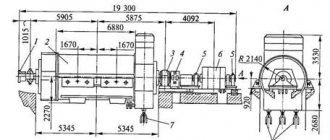
Separators for 220 kV are made in the form of three separate poles, each of which is controlled by an independent drive. The separator is switched off automatically under the action of wound springs when a blocking relay or a shutdown electromagnet is activated, releasing the free release mechanism of the drive. The separator is switched on manually. Designs of short circuiters and separators: In Fig. 4.1.1. a short circuiter for a voltage of 35 kV KZ-35 is shown. Dimensions for a 110 kV short circuit are given in parentheses. Rice. 4.1.1 Short circuiter KZ-35 A support insulator 2 is installed on the steel box 1. At the top of the support insulator there is a fixed contact 3, which is under high voltage. Movable grounded contact – knife 4 is mounted on shaft 5 of the short-circuit drive. Base 1 is isolated from the ground. Shaft 5 is acted upon by a drive spring, which is wound up in the disconnected state. To turn on, a command is sent to the drive electromagnet, which releases the mechanism latch. Under the action of the spring, the knife moves in a vertical plane and grounds contact 3. The turn-on time of such a short circuit is 0.15-0.25 s. Rice. 4.1.2. Separator The design of the OD-220 separator for a voltage of 220 kV is based on a two-column disconnector with blades 1 rotating in a horizontal plane, Fig. 4.1.2 The columns 2 are driven by a spring drive 3 with electromagnetic control. In the on position, the actuator springs are grounded. When a command is given, the spring is released and the contacts move apart in 0.4-0.5 s. |
Short circuit and separator device
Let's briefly talk about the design of the electromechanical devices shown above, this will be useful in explaining their operating principle. Let's start with the separator; its simplified drawing is presented below (Fig. 3 1).
Figure 3. 1) separator design; 2)short circuit design
Designations (part 1 separator design):
- A1 – insulating posts.
- B1 – rotating rods with knives installed in contacts.
- C1 is a spring mechanism that drives the rotary rods.
- D1 – platform.
- E1 – a cabinet with an electromagnetic “trigger” mechanism that releases a spring drive that separates the contact parts.
Both the devices themselves and the mechanics of their operation are not complicated. We have already mentioned that the separator is used when the voltage is removed from the network, that is, when the switches on the supply line are turned on. Consequently, there is no need to install special vacuum arcing contact chambers on the disconnectors.
Now let's look at the main design elements of the short circuit (Fig. 3 2):
- A2 – main (support) insulator rod.
- B2 – fixed rod with contact knives.
- C2 – spring drive.
- D2 – platform on which the short circuit is installed.
- E2 – cabinet for electromagnetic drive and current transformer.
- F2 is a movable grounded rod that closes the poles of the short circuit.
Structurally, the KZ-35 short circuiter, as well as other models that create an artificial interphase short circuit, have several differences from the device shown in the figure. Since a linear short circuit is simulated, the movable one is not connected to the ground, it is connected to another phase. Accordingly, the structure is equipped with another insulator-rack.
DISCONNECTERS, SHORT CIRCUITS, SEPARATORS
BASIC CONCEPTS
Disconnectors are devices designed to turn on and off sections of the electrical network or electrical installations that are not under load.
Using disconnectors you can turn off and on: magnetizing current of power transformers - no more than 3.5 A at a voltage of 6 kV and 3 A at 10 kV; charging current of buses, equipment, overhead and cable lines; ground fault current – no more than 4 A at a voltage of 6 kV and 3 A at 10 kV. With insulating partitions between the poles of the disconnectors, the on and off currents can be 1.5 times greater.
During repair work, a disconnector creates a visible gap between the parts that remain energized and the devices taken out for repair.
The value of the current switched off by the disconnector depends on its design (vertical, horizontal arrangement of blades), on the distance between the poles, on the rated voltage of the installation, therefore the admissibility of such an operation is established by instructions and guidelines. The order of operations when switching off the magnetizing current of the transformer also plays an important role. For example, transformers that have an on-load control device (OLD) must be switched to underexcitation mode, since the magnetizing current decreases sharply with a decrease in induction in the magnetic circuit, which depends on the supplied voltage. In addition, when disconnecting an unloaded transformer, it is necessary to first effectively ground the neutral, if in normal mode the transformer operated with an ungrounded neutral. If a grounding reactor was connected to the transformer neutral, it must first be disconnected.
If there is a disconnector and a separator in the circuit, then turning off and turning on the magnetizing current and charging currents should be performed by separators that have a spring drive, which allows you to quickly perform this operation.
Disconnectors play an important role in electrical installation circuits; the reliability of the entire electrical installation depends on the reliability of their operation, so the following requirements are imposed on them:
— creation of a visible gap in the air, the electrical strength of which corresponds to the maximum impulse voltage;
— electrodynamic and thermal resistance when short-circuit currents flow;
— exclusion of spontaneous shutdowns;
— clear switching on and off under the worst operating conditions (icing, snow, wind).
Depending on the number of poles, disconnectors can be single- and three-pole, by type of installation - for indoor and outdoor installations, by design - chopping, rotary, rolling, pantographic and hanging type. According to the installation method, disconnectors with vertical and horizontal blades are distinguished.
Short circuiter is a switching device designed to create an artificial short circuit in an electrical circuit. Short circuiters are used in simplified substation circuits in order to ensure the disconnection of a damaged transformer after an artificial short circuit is created by the action of relay protection of the supply line.
In 35 kV installations, two poles of a short circuit are used, when triggered, an artificial two-phase short circuit is created. In installations with a grounded neutral (110 kV and above), one pole of the short circuit is used.
The separator does not differ in appearance from the disconnector, but it has a spring drive to disconnect it. The separator is switched on manually. Separators, like disconnectors, can have grounding blades on one or both sides. The disadvantage of existing designs is the rather long shutdown time (0.4–0.5 s).
Separators can disconnect a de-energized circuit or the magnetizing current of a transformer.
Separators and short-circuiters of an open design do not operate reliably enough in adverse weather conditions (frost, ice). In operation, there are cases of their failure to operate. To replace these designs, separators and short-circuiters with a contact system located in a closed chamber filled with SF6 gas have been developed.
DISCONNECTOR DESIGN
For internal installations, disconnectors can be single-pole (RVO) or three-pole (RV, RVZ, RVFZ, RVK and RVRZ). Three-pole disconnectors can be made on a common frame or on separate frames for each pole. The individual poles are combined by a common shaft connected to the disconnector drive.
For currents up to 1000 A, the disconnector knife is made of two copper strips; for higher currents, knives made of three or four strips are used. Just as in busbar structures, the best use of material at high currents is achieved if the fixed contacts are box-shaped and the disconnector knives are trough-shaped.
In chopping-type disconnectors, the knife rotates around one of the fixed contacts, the movement of the knife is transmitted from the shaft through porcelain rods. The necessary pressure in the contacts is created by springs.
Let us consider the design of the contact system of chopping type disconnectors, shown in Fig. 4.1.
A copper bus bent at a right angle is fixed to the insulator 1, which is a fixed contact 2. The side parts of contact 2 are machined to a cylindrical surface, so a linear contact is formed with the blade plates 6. Springs 4, mounted on rod 5, press on steel plates 3, which with their protrusion press the knives to the fixed contact. The greater the pressure in the contact, the lower the contact resistance, but the greater the wear of the contacts due to friction during switching on and off, and the greater the force that must be applied when operating the disconnector.
When short circuit currents pass, electrodynamic forces are created at the points where the current passes from the knife plates to the contact, tending to push the knives away from the contact. On the other hand, the knife plates are attracted to each other due to the interaction of currents in the same direction. At high short circuit currents, the repulsive forces may be greater than the attractive forces of the knife plates, this will lead to the knife plates being thrown away from the contact, causing an arc, i.e., to an accident. To avoid this, the disconnectors are provided with a “magnetic lock” device. It consists of two steel plates 3 located outside the knife, which, firstly, serve to transmit pressure from the springs, and secondly, being magnetized by short circuit currents, they are attracted to each other and create additional pressure in the contact.
Rice. 4.1. Contact system of chopping type disconnectors:
1 – insulator; 2 – fixed contact; 3 – steel plates; 4 – springs;
5 – rod; 6 – knife; 7 – axis
The contact system of the disconnector on the second insulator has the same design, but the contacts will be sliding, hinged, and not opening, since the knife rotates around axis 7.
Three-pole disconnectors are equipped with mechanisms for switching on and off current-carrying blades and grounding blades. The moving contacts are connected to the levers of the tripping mechanisms by rods made of porcelain or other insulating material. The limitation of the stroke of the knives and the impossibility of spontaneous shutdown is ensured by the drive mechanism, and the density of the fixed and moving contacts of the disconnectors is provided by spring devices.
The design of the disconnectors does not provide for fixing the knives in the off position. To avoid spontaneous activation, disconnectors cannot be installed on horizontal planes with their knives located above the plane. The disconnector frame has a grounding bolt, which allows it to be connected to a branch from the grounding loop.
In Fig. 4.2 shows a three-pole disconnector RV-6-10 for indoor installation.
Copper or steel grounding blades 6 of the RVZ disconnector shown in Fig. 4.3, are welded to a steel shaft 7, which rotates in the holes of the plates attached to the frame 2. The shaft is connected by a flexible copper connection 8 to the frame 2 of the three-pole disconnector. Between the shaft of the disconnecting blades and the shaft of the grounding knives there is a blocking rod 10, which prevents the switching on of the disconnectors when the grounding knives are turned on and the switching on of the grounding knives when the disconnectors are turned on.
Contact pole system of vertical chopping type. To increase dynamic resistance, each contact knife 1 is equipped with “magnetic locks”. The pole contact system is mounted on four support insulators. The movement of the knives is transmitted through an insulating porcelain rod 5. To reduce the opening and closing forces, a mechanism is used to relieve contact pressure. Grounding knives 6 can be located on the side of the hinged or detachable contact or on both sides. In a three-pole installation, they are short-circuited by a common copper busbar.
Rice. 4.2. Disconnector RV-6-10:
1 – frame; 2 – shaft; 3 – lever; 4 – support insulator;
5 – fixed contact; 6 – knife; 7 – rod with insulator
Rice. 4.3. Disconnector RVZ-6-10:
1 – porcelain rod; 2 – frame; 3 – levers; 4 – insulator; 5 – fixed contact;
6 – knife; 7 – shaft with grounding knives; 8 – flexible connection; 9 – grounding bolt;
10 – blocking rod
In Fig. Figure 4.4 shows a disconnector type RVRZ for a voltage of 20 kV, rated current 8 kA, designed for a maximum through short-circuit current of 300 kA and a maximum thermal resistance of 112 kA (with a distance between poles of 700 mm).
Rice. 4.4. Chopping type disconnector for indoor installation
with two grounding blades RVRZ-2-20/8000 (one pole):
1 – movable main contacts; 2 – fixed contact; 5 – porcelain rod;
4 – support insulator; 5 – frame; 6 – grounding knives; 7 − mechanical interlocking between the main and grounding blades
The grounding knives have a mechanical lock that does not allow them to be turned on when the main knives are turned on. To control the grounding knives, a manual lever drive is used, consisting of a system of levers that transmits movement from the handle to the shaft (PR), or a worm drive (WF). Switching on and off the main knives is carried out by an electric motor drive (PDM), which allows these operations to be performed remotely.
In the on and off position, the disconnector is securely fixed by a system of drive levers to prevent spontaneous shutdown or activation.
For installation in complete shielded conductors, rolling-type disconnectors with a translational movement of the knife are used. These disconnectors are designed for high currents (12000, 14000 A). The fixed contacts are made in the form of boxes made of sheet copper and are mounted on support insulators screwed to the frame. The moving contact is made of eight box-shaped busbars connected to each other by a special mechanism. The pressure in the contacts is created by springs. When the disconnector is turned off, by turning the insulator, the cam device of the mechanism is set in motion, which presses the moving contacts away from the stationary ones by several millimeters. Then the entire moving contact rolls on rollers from right to left, turning off the disconnector. When turned on, the movable contact first moves from left to right, and then the cam device releases the box-shaped tires of the movable contact and they are pressed against the fixed contacts by springs. This switching off and on without friction in the contacts makes it possible to use a lightweight motor drive (PDV-12), as well as reduce contact wear.
Disconnectors installed in open switchgears must have appropriate insulation and reliably perform their functions in adverse environmental conditions.
In Fig. Figure 4.5 shows such a disconnector (RNV-500) with vertical movement of two half-knives. In the off position, its height is 8.45 m. The disconnector has two grounding knives, the drive of the main knives is electric (PDN), the grounding knives are manual.
Horizontal rotary type disconnectors are produced for voltages of 10 - 750 kV. The widespread use of these disconnectors is explained by their significantly smaller dimensions and simpler control mechanism. In these disconnectors, the main blade consists of two parts, just like the RNV disconnector, but they move in a horizontal plane when the insulator columns on which they are attached are rotated. This is a horizontal rotary disconnector RNDZ-2-110, shown in Fig. 4.6.
One pole is the leading pole and the drive is connected to it. The movement to the other two poles (driven) is transmitted by rods. Disconnectors may have one or two grounding blades. The contact part of the disconnector consists of lamellas fixed at the end of one knife, and a contact surface at the end of the other knife. When turned on, the knife fits between the slats. The pressure in the contact is created by springs.
In horizontal rotary disconnectors, when disconnected, the knife “breaks” into two parts, so the operation of the drive is greatly facilitated in the event of icing of the contacts. In chopping-type disconnectors, to destroy the ice crust, a translational-rotational movement was imparted to the knife, which complicated the kinematics of the drive. 330 - 750 kV disconnectors are equipped with ice-proof covers that cover the contacts.
Rice. 4.5. Disconnector for outdoor installation, vertically rotating type RNV-500:
1 – drive mechanism of grounding knives; 2−frame; 3 – grounding bus; 4 – grounding knife; 5 – insulator; 6, 9, 12 – screens; 7−pin; 8 – connecting bus;
10 – main knife with lamellas; 11 – main knife with spatula; 13 – PDN type drive
Rice. 4.6. Horizontal rotary disconnector RNDZ-2-110:
1 – frame; 2 – support insulator; 3 – tip for connecting busbars;
4 – flexible connection; 5 − main knife with lamellas; 6 – main knife without lamellas;
7 – grounding knives; 8 – thrust to the drive; 9 - drive
The suspended disconnector (Fig. 4.7) has a movable contact system consisting of a weight 5 equipped with spring legs 6 and contact tips 7, to which conductors 9 made of two aluminum pipes are welded. This entire system is suspended on garlands of insulators 3 to the portal. A fixed contact in the form of a ring 8 can be installed on a busbar insulation support, as well as on current and voltage measuring transformers. The cable control system consists of an electric motor drive 10, a cable 1, a counterweight 2, and blocks 4. In the off position, the moving contact is raised. When the disconnector is turned on, by rotating the drive drum, the counterweight rises up, and the movable contacts, under the influence of their own weight, move down and the tips 7 come into contact with the ring 8 - the circuit is closed.
Rice. 4.7. Hanging type disconnector RPD-500:
1 – cable; 2 – counterweight; 3 – garland of insulators; 4 – block; 5 – load; 6 – springy “feet”; 7 – contact tips; 8 – fixed contact; 9 – conductors;
10 – electric motor
For electrical installations of 1150 kV, two-column disconnectors with two telescopic knives have been developed, moving when switched on in a horizontal plane towards each other.
SHORT CIRCUIT DESIGN
The design of the short circuiter KZ-35 is shown in Fig. 4.8.
Rice. 4.8. Short circuiter KZ-35:
1 – base; 2 – grounding knife; 3 – fixed contact;
4 – insulating column; 5 – insulating insert; 6 – PRK-1 drive; 7 - traction;
8 – flexible connection to the grounding bus
The short-circuit drive has a spring that ensures that the grounded knife is connected to a fixed contact that is energized. The impulse for the drive operation is supplied from the relay protection. Disabling is done manually. When turning on the short circuit, in order to avoid arcing and damage to the device, it is necessary to ensure a high speed of movement of the knife. In existing designs, the switching time of the short circuiter is 0.12 - 0.25 s.
Short circuiters KE-110 and KE-220 are made in the form of one pole. The KE-110 pole (Fig. 4.9) consists of a base 5 and a contact chamber 2. In the base, isolated from the ground, there is a spring activation mechanism and an oil buffer.
SF6 gas leaks are compensated from a cylinder connected through a filter to the internal cavity of the contact chamber. The pressure is controlled using a pressure-vacuum gauge. The PPK spring drive provides remote switching on and off of the short circuiter. A current transformer 7 is installed on the grounding bus 4.
Rice. 4.9. Closed type short circuiter with SF6 gas filling KE-110:
1 – contact output; 2 – contact chamber; 3 – hydraulic valve;
4 – connection of the grounding bus; 5 – base; 6 – pressure and vacuum gauge;
7 – current transformer TSHL-0.5; 8 – drive; 9 - traction; 10 – insulator;
11 – cylinder with SF6 gas; 12 - filter
The contact chamber of the short-circuiter (Fig. 4.10) has one gap of 90 mm and consists of a porcelain body and two vertically located electrodes. Fixed contact 2 has a terminal for connecting a current-carrying bus. The moving contact is connected to the grounding bus through flexible connections. The cavity of the contact chamber is filled with SF6 gas with an excess pressure of 0.3 MPa.
Rice. 4.10. Contact chamber of short circuiter KZ-110:
1 − bag of silica gel; 2 – fixed contact; 3 – porcelain body; 4 – screen; 5 – moving contact; 6 – flexible connection; 7 – oil hydraulic seal;
8 − stuffing box seal
SF6 gas has high electrical strength. At atmospheric pressure, its strength is 2 - 3 times higher than air, and at a pressure of 0.3 MPa, the strength of SF6 gas is comparable to the strength of pure transformer oil. SF6 gas does not burn and does not support combustion, therefore devices with SF6 gas are not dangerous in terms of explosion and fire. When the pressure inside the chamber decreases to atmospheric pressure, the gap between the contacts can withstand the highest operating voltage without breaking through. The tightness of the chamber is ensured by gaskets made of rubber rings between the porcelain bodies and metal flanges (not shown in the figure) and a hydraulic shutter at the point where the movable rod passes.
The lower contact is a rod shielded by a cylinder. Fixed socket type contact. The contact lamellas are protected from burning by a screen.
The short circuiter KE-220 for 220 kV has two contact chambers of the same design.
DESIGN OF SEPARATORS
In Fig. 4.11 shows the separator pole of the OD-35 brand. These separators are produced on the basis of horizontally rotating two-column disconnectors of the RLND series and can be used for automatic shutdown when the separator is turned on manually and for automatic or remote switching on and off.
Rice. 4.11. Separator pole OD-35 in the on position:
1,2 – columns of rod support insulators; 3,4 – moving contacts;
5 – contact jaws; 6 – clamps; 7 – flexible connections; 8 – drive; 9 – grounding knife
The energy of the charging springs located at the base of the separators can significantly reduce energy consumption for the switching operation and speed up the shutdown of the separators. If the operation time of the RND disconnector with electric motor control is 5 - 10 s, then for the separator it is no more than 1 sec.
Each pole of the 35 kV separator has a shaped steel base, shafts with levers and two columns of rod support insulators 1 and 2 (ST-35), on which the current-carrying system of the separator is mounted. The movable contacts of the separator consist of two flat half-knives 3 and 4. On the knife 3, contact jaws 5 are mounted, equipped with flat steel springs. When switched on, knife 4 is cut between jaws 5 of knife 3. When switched off, both knives 3 and 4 of the separator are rotated 90° in the horizontal plane.
Switching the knives on and off is carried out by simultaneous rotation of both insulators by a spring. The design of the knives and contact system during operations makes it possible to crush the formed ice, while the insulators will not experience significant bending forces. The separator is controlled by a special automatic drive 8 (ShPO or ShPPO). The grounding knife 9 of the separator has a conventional manual drive 10 (PRN-110M).
A closed separator with SF6 gas filling (Fig. 4.12) is designed to switch off and on the magnetizing currents of power transformers and charging currents of lines. The OE-110 separator provides automatic switching on and off.
Rice. 4.12. Closed separator with SF6 gas filling OE-110/1000:
1 – upper flange; 2 – fixed contact; 3 – screen; 4 – contact spring;
5 – moving contact; 6 – insulating column; 7 – oil hydraulic seal;
8 – base; 9 – thrust to the drive; 10 – buffer; 11 – pressure and vacuum gauge;
12 – traction to fixed contact
Three poles are mounted on a common base 8. Current-carrying wires are connected to the contact terminals on the upper and middle flanges. Inside the contact chamber there is a fixed socket-type contact and a hollow movable contact with the screen. Switching occurs due to the force of the springs of the PPO drive. The pressure in the contacts is created due to the compressed spring 4 and the springy socket contact. Shutdown occurs automatically due to shutdown springs located at the base of the separator.
There are no special devices for extinguishing the arc, since SF6 gas has high electrical strength, and the separator is designed to disconnect currents of no more than 20 A. The gap between the contacts in the off position is 90 mm. The excess pressure of SF6 gas in the contact chamber is 0.3 MPa, but even if the SF6 gas leaks and the pressure drops to atmospheric pressure, the gap between the contacts can withstand, without breaking through, the highest operating voltage of 126 kV. To hermetically seal the movable rod when exiting the chamber, an oil hydraulic seal 7 of the same design as in the short circuit is used.
The contact chamber of the 110 kV separator is a module for higher voltage devices. So, in a 220 kV separator there should be two chambers.
The advantages of closed circuit short circuiters and separators are precise operation and short on and off times.
The control circuit for the short-circuiter and separator installed at the dead-end substation is shown in Fig. 4.13.
Line L goes to the substation, at the supply end of which high-speed protection and time-delay protection are installed. In the circuit under consideration, the power supply for the shutdown electromagnets of the separator YAT1 and the switch YAT2 on the voltage side of 6-10 kV, the intermediate relay KL1, as well as the winding KL2.2 of the on-off relay KL2 is carried out from pre-charged capacitors C1-C4 connected through the isolation diodes VD1-VD4. To charge the capacitors, chargers of the BPZ-401 and BPZ-402 types were used.
When promptly shutting down the substation, switch Q2 on the low voltage side is turned off using key SA1, and then switch QR is turned off using key SA2. The reverse order of disconnection (first QR and then Q2) is not possible, since the auxiliary contact Q2.1 of the switch prevents the disconnector from disconnecting, which can only disconnect the no-load current of the transformer. The substation is switched off via the telecontrol channel when the contacts KST.1 and KST.2 are closed.
If the transformer is damaged and there is an emergency shutdown, there can be two cases: only the transformer protection is triggered; Together with the transformer protection, the line protection is triggered and opens switch Q1.
In the first case, protecting the transformer with contact A.2 closes the circuit of the contactor KM1 for switching on the short circuiter QN. After QN is turned on, the protection turns off switch Q1. In this case, the condition for disconnecting the QR separator is the absence of current in the circuit of the protected transformer, the switched position of the QN short-circuiter and the absence of current in its circuit. To obtain this information, use current relays KA1 and KA2 (Fig. 4.13, a) and auxiliary contacts of the short circuiter QN.1. Relay contacts KA1, KA2, auxiliary contact QN.1 are connected in series to the relay circuit KL1, which, when activated, closes contact KL1.1 in the YAT1 circuit and acts to turn off the separator (Fig. 4.13, b).
When the short-circuiter is turned on, its auxiliary contacts QN.1 may close before the main contacts, and the separator will begin to turn off. In this case, it turns off the short circuit currents, which leads to an accident. To avoid this, use an intermediate relay KL1 with a delay when activated.
| b) |
| A) |
Rice. 4.13. Control circuit for short circuiter and separator
If, together with the transformer protection, the line protection is triggered and the Q1 switch is turned off before the QN short circuiter is turned on, then the auxiliary contact QN.1 in the KL1 relay winding circuit remains open. In this case, the QR separator is switched off during a dead pause due to the action of the two-position relay KL2, contact KL2.1, auxiliary contact QN.1. The on-off relay switches when the transformer protection is triggered (contact A.1 closes).
The normal operation of the switched-off substation is restored by maintenance personnel.
Control questions
1. Purpose of disconnectors. What operations are allowed to be performed
disconnectors?
2. By what criteria are disconnectors classified?
Describe the design and applications of the RV-6-10 type disconnector.
3. Explain the design of the disconnector type RVZ - 6-10.
4. Tell us about the design and principle of operation of the RVK-20 type disconnector.
5. Tell us about the design and principle of operation of the RVN-500 type disconnector.
6. Explain the purpose of short circuiters and separators.
7. Tell us about the design and principle of operation of the short circuiter type KZ-35.
8. Tell us about the design and principle of operation of the short circuiter type KE-110.
9. Tell us about the design and principle of operation of the OD-35 type separator.
10. Tell us about the design and principle of operation of the separator type OE-110.
11. Describe the automation circuit between the short circuiter and the separator.
Operating principle
The mechanics of operation of these devices are quite simple; for the separator it is as follows: when a signal is received, a relay is triggered that turns off the electromagnet, which blocks the spring mechanism. As a result of the separator drive being activated, its rotating rods are moved in different directions, opening the contacts. The signal for shutdowns is supplied by the relay protection control circuits.
Disconnectors are used only with short circuiters. This is due to the fact that with the help of the latter, a short-circuit current can trigger the relay protection, both at the current high-voltage substation and at the one to which the supply power line is connected. The short-circuiter can be triggered by a transformer protection signal or manually if necessary.
As soon as the start signal is received, the locking electromagnet of the spring mechanism is turned off and under its influence the moving contact is set in motion. As a result, the short circuit will cause a short circuit in the line, which will instantly activate the relay protection. Based on its signal, the high-voltage switches of the power transmission line will operate. Since the response speed of the disconnectors is significantly lower, they will disconnect an already de-energized line.
To consolidate the material, let's look at a few examples.
Operation of a short-circuiter without a separator
Below is a schematic electrical diagram of a substation where a short circuit is used without using a separator.
Substation diagram 110/10
Meaningful designations:
- A – Line breaker in the high-voltage part of the transformer substation.
- B – Short circuit.
- C – Power transformer.
In this circuit, the short circuiter will work as follows:
- If problems arise with transformer “C”, it sends a signal to short circuit “B”.
- The mechanism of the electromechanical device produces a short-circuited connection.
- The short circuit is monitored by relay protection and generates a signal at LR “A”.
- The power switch trips and disconnects the input.
After the cause of the protection operation has been established and eliminated, the switch is turned off (that is, the input line is connected).
The example described above of organizing protection at a substation is quite efficient and reliable, but the use of a switch in this case is not justified due to its high cost.
Collaboration
If the design is of an open type, then the operation of the above-mentioned devices is unstable (even to the point of failure to work), since they are sensitive to frost and ice. For this reason, closed gas chambers were developed. Gas can leak and in this case it is restored from a cylinder, which is attached to the chamber shell. The pressure in such chambers is constantly regulated by a pressure-vacuum gauge.
The short-circuiter contains a contact chamber made of porcelain and 2 electrodes with a single gap of 0.9 cm. There is an output for attaching a current-conducting bus to the fixed contact. Flexible links connect the contact to each other. The contact chamber is filled with gas with a pressure of 0.3 MPa. The gas in the chamber cannot be burned, and this does not pose a danger in the event of an explosion or fire. Based on this, arc extinguishing devices do not make sense in design. The bottom contact is similar to a rod with a cylinder in the form of a screen and is of the rosette type.
The collaboration scheme looks like this:
Scheme of operation of a separator with a short circuit
Where:
- Q – switch;
- QR – separator;
- QN – short circuit;
- T1, T2 – power transformers;
- TA1, TA2, TA3 – current transformers;
- YAT – disabling the separator;
- YAC – switching on the short circuit.
This system, combination is almost analogous to a high voltage switch. In the event of an emergency within the protected zone, the protective element is a power transformer, which, through certain processes, de-energizes all consumers of this transformer.
Also, during times when there is no current supply, the separator is turned off to prevent its own rupture from the effects of current. This system is used in networks with high current. As we said above, the OD-KZ system is cheap, but nowadays it is already outdated and is being replaced by newer switches. You can learn more about this issue by watching the video:
Overview of the OD-KZ system
Power oil transformers tm and tmg
Joint operation of the short-circuiter with the separator
Now let's look at the OD-KZ combination using the example of a substation with two transformer groups powered from one incoming power line.
Example of a substation with OD-KZ
Designations:
- Vk1 – power switch VL (closed).
- Vk2, Vk3 – power protective switches on the low side (closed).
- Vk4 – sector switch (open).
- Kz1, Kz2 – short circuits (open).
- Od1, Od2 – separators (closed).
- Tr1, Tr2 – power transformers 220/10
To get an idea of how this circuit works, consider a situation where one of the transformers fails:
- Let's imagine that the insulation in Tr2 is broken, which leads to the formation of electric discharges that decompose the oil, which is detected by the gas relay and sends a corresponding signal to the control panel of the short circuiter Kz2.
- The signal received by the blocking relay causes it to operate. The mechanism is unlocked and the spring drive pushes the movable rod, as a result, two phases are closed.
- This turns on Vk1, which leads to the disconnection of the supply line and the de-energization of Tp1 and Tp2. A short circuit also causes a corresponding reaction of relay protection Tp2, it turns off Vk3 (the load is removed) and starts Od2. Since the latter has the slowest response speed, it is activated last when the overhead line and load are disconnected.
- After a certain delay, Vk1 reconnects the power line (the automatic restart system is triggered).
- Automatic transfer of reserve includes VK4.
As a result, only Tr1 works at the substation, from which both sections are powered.
2.3. Operating principle of separators and short circuiters
As an example of the use of short circuiters and separators in Fig. 2.3. The diagram of power supply from one line of two transformer groups T1 and T2 is shown.
220kV
Rice. 2.3. Switching diagram with separators and short-circuiters In addition to the high-speed short-circuiters KZ-1 and KZ-2, the circuit includes separators OD-1 and OD-2, which are closed during normal operation. Suppose, due to deterioration of the insulation of transformer T1, electrical discharges occur inside it, which lead to the decomposition of oil and the release of gas. Gas bubbles rising upward trigger the gas relay. The signal from this relay turns on the short circuit and an artificial short circuit occurs in the circuit. Under the action of the short-circuit current, the protection switch B1 is triggered and both transformers T1 and T2 are de-energized. Using the relay protection of transformer T1, switch B2 is also turned off, after which, after a certain delay, separator OD1 is turned off. Then, since the artificial short circuit mode was turned off, switch B1 is turned on again, that is, the automatic reclosure of this switch is triggered. If before the accident switch B4 was turned off, then after turning on switch B1 it can be turned on, that is, the ATS (automatic transfer switch) will work. At the same time, power will be restored to consumers on the 10 kV buses of the first transformer group. The higher the rated network voltage, the higher the efficiency of such a circuit. This effect is achieved due to the absence of switches on the 35-220 kV side, as well as batteries and compressor units. The substation area is reduced. Construction time is reduced.
- Back
Peculiarities
There are no ideal systems; naturally, short circuiters and separators have a number of features, some of which can be considered disadvantages. For example, the latter sharply reduces the reliability of operation during glaciation. This problem is solved if closed-type disconnectors with SF6 gas filling are used. Such devices are more expensive than conventional models, but are still cheaper than power switches.
There are also complaints about short circuiters, in particular regarding their response speed (it is about 400-500 ms). The simplest solution in this case is to use structures that use a powder charge as a drive.
Otherwise, the operation of the devices described in the article is fully justified, as evidenced by the popularity of the OD-KZ combination.