What is a reed switch
A reed switch is a type of relay. The word "reed switch" is an abbreviation for the words "sealed contact". This is the main feature of this electronic device.
Sealed contact
Conventional electromagnetic relays have movable and fixed metal contacts. There is an air gap between them. When they close or open, an electric arc is formed. The air between the contacts acts as a conductor. Arcing damages the contacts and shortens the life of the relay.
A reed switch works in a similar way, but the terminals are in an inert gas environment. For this reason, arc ignition is not possible. Consequently, the reed relay contacts do not burn out, which increases the service life of the electronic device.
Part device
The reed switch sensor looks like a small glass tube made of green translucent glass. There are wire leads on both sides. They allow you to solder the part to the board or connect wires to it. There are also three-pin models.
Inside the glass tube there is a cavity with an airless environment. The cavity contains contacts that are connected to the terminals of the device located outside. This part does not have semiconductors. Therefore, it can operate on alternating current.
Reed switches are quite varied in size. Small models have a length of 10-15 mm. The larger ones are the size of a palm.
This is interesting! There is a tendency to reduce the overall dimensions of reed switches. In 2021, the American company put into mass production a part with a tube length of 4.01 mm. In 2005, the Japanese also had achievements in this area and announced the production of a prototype with a flask length of 2 mm. However, these details have not yet received wide distribution.
Types of contacts
Reed switches have a classification similar to other types of relays. In terms of contact status, the following models exist:
- With normally closed contacts. If you bring a magnet close, the device's terminals open.
- With normally open contacts. If you bring a magnet close, the terminals will close.
- With changeover contacts. If the magnet is nearby, one group of terminals is closed. If the magnet is removed, the first group will open, but the second will close.
According to the contact arrangement, reed switches are divided into 2 types:
- With dry contacts. Made of solid metal.
- With wetted contacts. There is a drop of mercury inside. It reduces the contact resistance of the device and eliminates contact bounce.
From the point of view of the internal environment, there are 2 types of devices:
- Inside the tube is an inert gas (usually nitrogen).
- A vacuum environment is created inside. This reed switch is used in high voltage circuits, including 220 volts and above.
Vacuum reed switch with mercury
Types of reed switches
Like conventional contact products, according to their performance characteristics, reed switches are divided into:
- Switching devices designed for two positions with one reversible contact plate.
- Breakers, the design of which provides for a closed (in normal state) contact.
- Normally closed contacts with one open contact.
According to their design, switching elements of this class are divided into devices with dry switches and mercury samples. The first ones belong to the simplest products with all their inherent disadvantages. One of them is the so-called “bounce” of contacts, which refers to their parasitic vibrations when closing and opening. As a result, a single operation of the switching element causes a whole series of random switching, which is very dangerous for the operation of electronic circuits. The second samples differ in that a drop of mercury is placed in the inner zone of the sealed flask. It wets the switching contacts when triggered, eliminating chatter and reducing contact resistance.
Operating principle of a reed switch
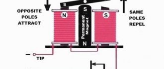
The contacts are activated under the influence of a magnetic field. Its source is usually a permanent or controlled electric magnet.
The field from the magnet easily penetrates through the glass into the sealed cavity. Once inside, it interacts with the metal contacts of the device.
The magnetic field sets them in motion, thereby closing or opening the electrical circuit connected to the terminals of the part. Therefore, to check the functionality of such a relay, it is enough to bring any magnet to it.
Operating principle of a reed sensor
Closing and opening contacts requires some magnetization time. It is measured in units of milliseconds, so in practice it is usually not taken into account. In most cases, it is acceptable to assume that the reed switch is triggered immediately when it enters a magnetic field.
Design, types and principle of operation
All reed switches are designed almost identically - it is a sealed glass bulb, inside of which there is a contact group. The contacts are magnetic cores that are welded into the ends of the flask, and their outer ends can be connected to an external electrical circuit.
Functionally, reed switches, like regular contacts, can be either making or opening contacts. The most widely used reed switches are those with short-circuit or “normally open” contacts. Let's take a closer look at its structure and principle of operation. So, it is a glass flask containing two iron plates. Each contact is made of ferromagnetic wire with a diameter of 0.5 mm, depending on the power and size of the reed switch. The contacting surfaces themselves are coated with noble metals: gold, ruthenium, palladium, rhodium, silver and alloys based on them. This coating reduces the contact resistance and increases the corrosion resistance of the contacts. When an “open” reed switch enters a magnetic field, the plate contacts are magnetized, attracted and closed.
Reed switch operation diagram
A reed switch that operates to open or a “normally closed” reed switch operates in exactly the opposite way. In this case, when exposed to a magnetic field, the contacts repel each other, breaking the electrical circuit.
Reed switches also vary in size. In recent years, there has been a trend towards the use of miniature reed switches - with a bulb length of less than 10 mm. With such dimensions, sensitivity, speed, and resonant frequency increase, and the chatter time decreases. For example, the Ryazan enterprise Ruselectronics has launched the production of miniature reed switches with a cylinder size of 7 mm.
If the reed switches are paired with an electromagnet, the design combining the reed switch and the electromagnet is called a reed switch relay.
Technical parameters of choice
When choosing, you should take into account a number of technical characteristics of this device. The main ones include:
- current switching capacity;
- maximum voltage;
- breakdown voltage of the gap between the contacts;
- contact resistance;
- maximum load power that can be connected to the terminals of the sealed contact;
- time of closing and opening of the device;
- field strength at which the reed switch will operate.
Additional Information! The contact resistance of contacts can increase as they wear out. It also depends on the strength of the magnetic field acting on the reed switch and its position in space.
Measuring basic electrical parameters
The electrical parameters of reed switches should be measured under normal climatic conditions, in the modes and conditions established in the technical specifications for specific types of reed switches. When carrying out measurements, measures must be taken to eliminate the influence of parasitic external magnetic and electric fields or to reduce them, and vibration of the reed switches should not occur, causing changes in parameters. When measuring electrical parameters, the reed switch must be controlled by a measuring coil without ferromagnetic materials. The requirements for the measuring coil and the position of the reed switch in it must correspond to those established in the specifications for specific types of reed switches.
Measurement of magnetomotive force of actuation, release and reset ratio
The measurement error due to the influence of external electric and magnetic fields should not exceed 0.5A and should not be more than 2%. The actuation MMF is determined by the value of the current flowing through the measuring coil at the moment the reed switch operates. The release MMF is determined by the value of the current flowing through the measuring coil at the moment the reed switch is lowered. The return coefficient is determined as the ratio of the release MMF to the actuation MMF. The moment of actuation and lowering of the reed switches under the influence of the control magnetic field is determined by monitoring the state of the reed switch circuit. When determining the actuation MMF and release MMF, a direct current must pass through the contact parts of the reed switch.
MMF actuation and MMF release of the reed switch are measured by smoothly measuring the current in the measuring coil. The current in the coil is increased at a rate of no more than 5 A-ms-1 to a value that provides an MMF equal to the saturation MMF; The saturation MMF is equal to 2.2 times the value of the highest MMF response for a group of reed switches. With MDS saturation, the reed switch is maintained for a time tH equal to at least 20 ms. The current in the coil is reduced at a rate of no more than 5A-ms-1 to a value that provides an MMF equal to the holding MMF. Further, at a speed of no more than 1 A-ms-1 until the reed switch is released. The moment of release is recorded. The current in the coil is reduced at a rate of no more than 5 A-ms-1 to zero. The reed switch is kept without current in the coil for a period of at least 20 ms.
The current in the coil is increased at a rate of no more than 5 A; ms-1 from zero value to a value that ensures MMF failure. They proceed to a speed of no more than 1 A-ms-1 until the reed switch operates. The moment of operation is recorded. If the reed switch fails to operate, the current in the coil is increased to the maximum MMF response value for this group of reed switches. If the last measured parameter is the MMF, then the current in the coil is abruptly reduced to zero or the measurement of the next parameter is continued.
MMF (A) is determined by the formula: MMF = Icat Ncat
It will be interesting➡ What is a tuning resistor: description of the device and its scope
where Icat is the current through the coil at the moment of actuation/release fixation; N – number of turns of the measuring coil (5000).
The return rate is determined by the formula:
Kv = MDS otp / MDS srab
The relative error in measuring MMF actuation and MMF release should not go beyond ±1 A when measuring MMF up to 20 A, ±2 A - from 20 to 80 A and ±5% - over 80 A with a probability of at least 0.95.
Using a reed switch in a sensor.
Timing measurements
Timing parameters are determined by measuring time intervals in accordance with the timing diagrams of the actuation and release of the reed switch. The generator of rectangular current pulses must provide at the output single pulses or a series of pulses with a duration of edges measured between the levels of 0.1 and 0.9 of their amplitude, no more than 50 μs on an active load and an amplitude that provides a working MMF in the measuring coil. The response and release time intervals are measured. When measuring bounce time, circuit breaks less than 10 µs are not taken into account.
Electrical resistance measurement
The resistance of the reed switch is measured with closed contact parts using a four-wire connection (current and potential) with direct reading devices or using a direct current voltmeter-ammeter method. Reed switch resistance is measured using an installation whose electrical block diagram is shown below:
G—current source; PV1, PV2 - millivoltmeters; RK - calibrated resistor; E – reed switch under test.
The current source G must meet the following requirements: provide a current in the reed switch circuit of no more than 0.1 A with an error within ±2.5%; have a maximum voltage on an open reed switch of no more than 6V.
Reed switch on the diagram.
Measuring the influence of external electromagnetic fields
A measuring coil with a reed switch is placed in space in three mutually perpendicular positions and the actuation MMF is measured in each position in two directions (in the second measurement, the coil is positioned so that its longitudinal field is rotated by 180°). From the obtained values, select the greater and the lesser. The difference between them should not exceed 0.5 A and be no more than 2%.
How to operate a reed switch
Reed switches close (open) contacts when exposed to a magnetic field. The field source is usually a permanent or electric magnet.
If we are talking about a permanent magnet, then the reed switch is in a closed state when the magnet is nearby. If you move it to the side by 5-7 mm, the contacts of the device will open.
With an electric magnet, you don't need to move anything. The reed switch tube is located inside the electromagnet coil. When voltage is applied to it, a magnetic field is generated. It keeps the terminals closed. If the voltage is removed from the electromagnet, the field will disappear and the terminals will open.
Electromagnetic switch with reed switch
Advantages and disadvantages
Like any electronic components, reed switches have advantages and disadvantages. Advantages:
- increased wear resistance;
- compact overall dimensions relative to conventional relays;
- absence of intrinsic noise and signal distortion;
- contacts are isolated from environmental dust.
Flaws:
- inability to work in conditions of extraneous magnetic fields;
- spontaneous opening and sticking of contacts at high currents;
- fragility, vibration intolerance;
- increased contact bounce due to their elasticity.
Reed switch control using a constant current coil
This method is most widely used when creating reed relays. The design of these relays is quite simple: a reed switch is simply placed inside the coil with current, and no additional springs or levers are required, like a conventional relay. The only drawback in this case is the small number of contact groups. If the coil is made with a thick enough wire that can pass a large current, then you can get a reed current relay. Such relays were widely used in high-power DC sources as a sensor for overload protection systems. Fine adjustment of the response level of such a sensor is carried out by a threaded mechanism, which allows the reed switch to be smoothly moved along the axis of the coil.
Reed switches in a green glass flask.
Advantages and disadvantages of reed switches
Like any thing, reed switches have their disadvantages and advantages. First, of course, let's talk about the advantages. Compared to conventional switching contacts, reed switches are almost 100 times more reliable than conventional open contacts. This reliability is due to higher insulation resistance (reaches tens of MegaOhms) and greater electrical strength: the breakdown voltage of some types of reed switches reaches several tens of kilovolts. Comparative characteristics of reed switches are given in the table below:
It will be interesting➡ Diode bridge - what is it?
The undeniable advantage of reed switches is their speed: for some models of reed switches, the switching frequency reaches 1000 Hz, and the response and release speeds are within the range (0.5 - 2.0 ms) and (0.2 - 1.0 ms), respectively. The service life of some reed switches reaches 4 - 5 billion operations, which is much higher than that for conventional unprotected contacts. Also, the advantages of reed switches include an easy way to coordinate with the load, as well as the operation of reed switches without the use of electrical energy sources.
Disadvantages of reed switches
Compared to the advantages, the disadvantages are probably not so great. Firstly, this is a small switching power. In addition, there is a small number of contact groups in one cylinder and for “dry” reed switches there is contact chatter. Disadvantages also include the fragility of the glass container and, in some cases, high sensitivity to external magnetic fields.
How to connect a reed switch.
Explanation of markings
On electrical circuit diagrams, the reed switch is designated as a circle with normally open or normally closed contacts. The symbol resembles an ordinary button surrounded by a circle.
In the technical documentation, the reed switch is marked with letters and numbers. For the designations of most such devices, the following is true:
- 1st character – name of the part (MK – magnetically controlled contact);
- 2nd symbol – type of contacts (A – normally open, B – normally closed)
- 3rd symbol – the letter “P” is indicated only on devices with mercury;
- 4th character – length of the flask in millimeters (two-digit number);
- 5th character – functional feature of the device (1 – low and medium power, 2 – high power);
- The 6th character is the serial number of the development.
Designation system for reed relays
For example, you can disassemble the MKA-14103 model:
- MK – magnetically controlled contact;
- A – closing;
- the letter “P” is missing, which means without mercury;
- 14 – flask length 14 mm.
- 1 – low or medium power;
- 03 – development order (useless in practice).
Simple examples of everyday use
The reed switch is a simple part, so radio amateurs willingly assemble various devices on it with their own hands. Below are 3 popular solutions that are implemented using this part:
- Signaling. A secret magnet is attached to the door (it is advisable to use neodymium). A door reed switch is installed on the cladding. It is necessary to fasten it so that when the passage is open, the reed switch terminals are open, and when the passage is closed, they are closed. As a result, the door status is converted into an electrical signal. It can also be converted into an alarm sound.
- Homemade on-board computer for a bicycle. In this case, the magnet is installed on the wheel or drive sprocket of the bicycle. The reed switch is fixed on the frame of the “iron horse”. The higher the speed of the bicycle, the more often the magnet comes into close proximity to the part. Using a microcontroller circuit, these pulses can be converted into the current speed of the bicycle or the distance traveled per day can be calculated.
- Use as a limit switch on moving mechanisms (for example, on automatic gates).
Additional Information! The electronics industry also produces reed switches for security alarms. Such amateur-class devices include the wireless door opening sensor ALD01. Professional systems use mortise reed switches, which do not attract attention. They allow you to hide the fact that the detector is operating.
The operating principle of a reed switch is based on its interaction with a magnetic field. If you bring a magnetized object to the reed switch, its terminals will close. And if you place this part in the field of a controlled electric magnet, you will get a relay with increased wear resistance.
This device should be selected based on the maximum permissible current and voltage. At the same time, it is necessary to take into account the operating conditions. Devices such as an electromagnetic intercom lock located near the reed switch can affect its operation.
Examples of practical use in everyday life
As promised at the beginning of the article, we present a couple of useful diagrams that use reed switches. Let's start with universal lighting control in the hallway. The principle of operation is as follows: when you open the front door, the light automatically turns on, and after a few minutes it turns off. If the lighting level is sufficient, the light in the hallway does not turn on.
Designations:
- Resistors: R1 – 68 kOhm, R2 – 33 kOhm, R3 – 470 kOhm, R4 – 10 kOhm, R5 – 27 kOhm.
- Capacitors: C1 – 0.1 µF, C2 – 100 µF x 25 V, C3 – 470 µF x 25 V.
- Zener diode and diodes: VD1 – KS212ZH, VD2 and VD3 – KD522 (1N4148), VD4 – KD209 (1N4004).
- Transistors: VT1 and VT2 – ÌRF840.
- SG1 – any regular reed sensor, for example, 59145-030.
- FR1 is a photoresistor, suitable for any type with a resistance in light of at least 8 kOhm, in the dark - 120-180 kOhm.
- Trigger D1 – K561TM2 (CD4013).
Setting up the circuit comes down to selecting resistance R1 to select the optimal delay time for turning off the lighting.
Now let's look at a simple home alarm circuit that also uses a standard reed switch for a door.
Designations:
- Resistors: R1, R2 and R3 – 100 kOhm, R4 – 33 kOhm, R5 – 100 kOhm, R6 – 1 kOhm.
- Capacitors: C1 – 100 µF x 16 V, C2 – 50 µF x 16 V, C3 0.068 µF.
- Diodes and LED: VD1 and VD2 – KD522 (1T4148), HL1 – AL307B.
- Transistors: VT1 – KT829, VT2 – K361.
- Microcircuit: K561LA7.
- S1 – reed sensor 59145-030.
The AC-10 sounder is used as a siren.
The circuit is powered by a 12 V battery with a capacity of 4 Ah.
Any technology can navigate the environment only with the help of special sensors that allow you to obtain the necessary information. They may be aimed at finding out an object's speed, state, current goals, or type of change in the environment. Reed sensors are considered one of the most useful. Why is this so?
