Last changes
14.09.2018
A new person who has the right to act without a power of attorney: Director Igor Nikolaevich Travichev
Lylov Sergey Fedorovich is no longer a person entitled to act without a power of attorney
19.11.2016
The address of the organization is excluded from the register of the Federal Tax Service Addresses indicated during state registration as the location of several legal entities
23.10.2016
The address of the organization is included in the register of the Federal Tax Service Addresses indicated during state registration as the location of several legal entities
18.08.2016
New license No. LO-33-01-002188 dated July 15, 2016, type of activity: Medical activities (with the exception of the specified activities carried out by medical organizations and other organizations included in the private healthcare system in the territory of the innovative)
Information about license No. LO-33-01-001245 dated 05/03/2013, type of activity: Medical activity (with the exception of the specified activities carried out by medical organizations and other organizations included in the private healthcare system in the territory of the innovative) has been removed.
01.08.2016
The organization is included in the Register of Small and Medium Enterprises, category: small enterprise
22.07.2016
New license No. LO-33-01-001245 dated 04/22/2013, type of activity: Medical activities (except for the specified activities carried out by medical organizations and other organizations included in the private healthcare system in the territory of the innovative one)
Basic data of three-winding transformers
| Type | SН, kVA | UNOM, kV | Losses, kW | UK, % | IХ, % | Dimensions, m | Weight, t | ||||||||||||
| VN | CH | NN | RH | RK | B-C | V-N | S-N | l | b | h | full | Third | Act. parts | Baka | oils | ||||
| full | Transport | ||||||||||||||||||
| 1 | 2 | 3 | 4 | 5 | 6 | 7 | 8 | 9 | 10 | 11 | 12 | 13 | 14 | 15 | 16 | 17 | 18 | 19 | 20 |
| VOLTAGE CLASS 35 kV. GOST 11920-73 | |||||||||||||||||||
| TMTN-6300/35 | 6300 | 35 | 10,5 13,8 15,75 | 6,3 | 12 | 55 | 7,5 | 7,5 | 16 | 1,2 | 5,2 | 4,3 | 4,5 | 26,5 | 19,8 | 10,5 | 5,1 | 7,3 | 6 |
| TMTN-10000/35 | 10000 | 36,75 | 19 | 75 | 8,0 | 16,5 | 7,0 | 1,0 | 6,0 | 4,3 | 5,2 | 35,6 | 26,4 | 14,4 | 7,5 | 9,8 | 7,2 | ||
| TMTN-16000/35 | 16000 | 10,5 13,8 | 28 | 115 | 0,95 | 6,5 | 4,5 | 5,5 | 47,0 | 34,6 | 20,3 | 9,9 | 12,6 | 9,1 | |||||
| VOLTAGE CLASS 110 kV. GOST 12965-74 | |||||||||||||||||||
| TMTN-6300/110 | 6000 | 115 | 38,5 | 6,6 11 | 17 | 80 | 10,5 | 17 | 6,0 | 1,2 | 6,2 | 3,5 | 3,4 | 42,5 | 37,6 | 15,7 | 8,4 | 15,4 | 13,4 |
| TDTN-10000/110 | 10000 | 23 | 76 | 1,1 | 6,9 | 3,7 | 5,4 | 52,3 | 45,0 | 22,0 | 11,0 | 16,8 | 13,8 | ||||||
| TDTN-16000/110 | 16000 | 26 | 105 | 10,5 | 1,05 | 7,3 | 4,5 | 5,7 | 67,7 | 61,0 | 29,5 | 6,0 | 21,0 | 16,0 | |||||
| TDTN-25000/110 | 25000 | 11 38,5 | 36 | 145 | 17 | 1,0 | 7,5 | 5,9 | 5,9 | 79,9 | 64,8 | 37,3 | 6,0 | 23,6 | 18,6 | ||||
| TDTN-40000/110 | 40000 | 6,6 | 50 | 230 | 0,9 | 7,5 | 5,0 | 6,2 | 103,1 | 88,1 | 53,5 | 7,2 | 27,7 | 22,1 | |||||
| TDTN-63000/110 | 63000 | 6,6 11 | 70 | 310 | 6,5 | 0,85 | 9,4 | 5,4 | 7,2 | 130,0 | 110,2 | 67,7 | 7,2 | 37,0 | 26,0 | ||||
| TDTN-80000/110 | 80000 | 102 | 390 | 0,6 | — | — | — | 150 | 121 | 80 | 8,2 | 38,2 | 28 | ||||||
| VOLTAGE CLASS 150 kV. GOST 12965-74 | |||||||||||||||||||
| TDTN-16000/150 | 16000 | 158 | 38,5 | 6,6 11 | 25 | 96 | 10,5 | 18,0 | 6,0 | 1,0 | 7,9 | 4,5 | 6 | 64,8 | 55 | 31 | 6,8 | 20,5 | 18 |
| TDTN-25000/150 | 25000 | 34 | 145 | 0,9 | 8 | 4,6 | 4,4 | 76,6 | 67 | 37 | 23,1 | 20 | |||||||
| TDTN-40000/150 | 40000 | 53 | 185 | 0,8 | 4,8 | 6,7 | 101 | 88 | 54 | 7,3 | 27,1 | 23 | |||||||
| TDTN-63000/150 | 63000 | 67 | 285 | 0,7 | 4,9 | 7,4 | 131 | 109 | 69 | 12,1 | 34,4 | 27 | |||||||
| 1 | 2 | 3 | 4 | 5 | 6 | 7 | 8 | 9 | 10 | 11 | 12 | 13 | 14 | 15 | 16 | 17 | 18 | 19 | 20 |
| VOLTAGE CLASS 220 kV. GOST 15957-70 | |||||||||||||||||||
| TDTN-25000/220 | 25000 | 230 | 22 | 6,6 11 | 41 | 135 | 12,5 | 20,0 | 6,5 | 1,2 | 10,2 | 5,1 | 8,1 | 95 | 94,9 | 49 | 8,8 | 38,5 | 29 |
| TDTN-40000/220 | 40000 | 38,5 | 66 | 240 | 22,0 | 9,5 | 1,1 | 6,7 | 5,4 | 9,5 | 126 | 105 | 57 | 43 | 33 | ||||
| TDTN-63000/220 | 63000 | 91 | 320 | 24,0 | 10,5 | 1,0 | 8,9 | 4,7 | 7,6 | 152 | 134 | 78 | 12 | 41,5 | 36 | ||||
Notes:
1. Decoding of letters and numbers of the transformer symbol: T after the type of cooling system means three-winding, the rest - see note 1 to table. basic data of two-winding transformers. 2. The power of the HV, MV, LV windings is 100% of the rated power each. 3. Voltage regulation under load is carried out:
a) for transformers of voltage class up to 35 kV inclusive, on-load tap-changer on the HV side, on the MV and LV sides - without branches; b) for transformers of voltage class 110÷220 kV OLTC in the neutral of the HV winding, the MV winding has branches and a tap-changer device with a regulation range at a current of up to 700 A and at a current from 700 to 1200 A, at a current above 1200 A the MV winding has no branches . 4. The value of the capacitances of the HV/MV/LV windings of some transformers, pF: 40000/110-12300/17300/18500; 25000/220-9500/12800/13500; 63000/150-14900/25600/26800.
Links and literature
How to decipher tire markings
. Rozhkova L.D., Kozulin V.S. Electrical equipment of stations and substations. - M.: Energoatomizdat, 1987. - 315 pp. Neklepaev B.N. Electrical part of power plants and substations. Textbook for universities. 2nd ed. - M.: Energoatomizdat, 1986.-310 pp. Rules for the technical operation of electrical installations. Approved by order of the Ministry of Fuel and Energy of Ukraine dated July 25, 2006. GOST R 52719–2007. Power transformers. General technical conditions. – M.: Standards Publishing House, 2007. – 45 pp. GOST 12.2.007.0–75. System of occupational safety standards. Electrical publication. General safety requirements. – M.: Standards Publishing House, 1975. – 12 p.. GOST 12.2.007.2–75. System of occupational safety standards. Power transformers and electrical reactors. Safety requirements. – M.: Standards Publishing House, 1975. – 5 p.
Characteristics of TDN 10000/110/6
- Characteristics
| Transformer type | TDN |
| Rated power Sn, MVA | 10 |
| Number of windings and type | Double winding transformer |
| HV side network voltage Unom. network, kV | 110 |
| HV winding voltage Uin, kV | 115 |
| MV winding voltage Uсн, kV | — |
| LV winding voltage Unnn, kV | 6,6 |
| No-load losses ΔPxx, kW | 14 |
| Short circuit losses ΔPsc, kW | 58 |
| Voltage Ukv-n, % | 10,5 |
| Current Ixx, % | 0,9 |
Main characteristics of the transformer
Figure 1.3 shows the appearance of the transformer TRDN-40000/110.
Figure 1.3 – Appearance of transformer TRDN-40000/110
In accordance with the accepted notation system, the abbreviation of the transformer TRDN-40000/110-U1 is deciphered as follows: T - three-phase transformer; P - the presence of a split low voltage winding; D - cooling is carried out with natural circulation of oil and forced air circulation; N - voltage regulation is carried out under load on-load tap-changer; 40000 – rated power of the transformer, kV•A; 110 – voltage class of the high-voltage winding, kV; U1 – climatic version, placement category according to GOST 15150. The main parameters of this transformer are given in Table 1.1 [].
Table 1.1 – Technical parameters of TRDN-40000/110-U1
| Rated frequency, Hz | 50 |
| Winding connection diagram and group | Υн/Δ-Δ-11-11 |
| Rated value of HV voltage, kV | 115 |
| Rated value of LV voltage, kV | 11 |
| Short-circuit voltage (HV-LV), % | 10,5 |
| No-load current, no more, % | 0,55 |
| On-load tap-changer control stages in the HV neutral | ±9x1.78% |
| Full service life, years | 25 |
The requirements for power transformers state that to ensure long-term and reliable operation of transformers it is necessary to ensure:
- compliance with the required load, temperature conditions and voltage levels;
- compliance with the characteristics of transformer oil and insulation within the established standards;
- maintaining transformer cooling devices, oil protection, voltage regulation, etc. in good condition.
Decoding
- T - three-phase,
- M - oil cooling system (natural oil circulation),
- N - presence of regulation under load,
- 6300 - rated apparent power (kVA),
- 110/6 - rated network voltage classes.
Parameters TMN 6300/110/6
| Sn, MBA | Uin, kV | Usn, kV | Unn, kV | ΔPx, kW | ΔPkvn, kW | ΔPkvs, kW* | Ukv-s, % | Ukv-n, % | Uks-n, % | Ix, % | SNN, MBA |
| 6,3 | 115 | — | 6,6 | 10 | 44 | — | — | 10,5 | — | 1 | — |
*Usually given for autotransformers.
Sн Total rated power of the transformer (autotransformer) in MVA; Uvn Rated voltage of the higher voltage winding in kV; Usn Rated voltage of the medium voltage winding in kV; Unn Rated voltage of the low voltage winding in kV; ΔPx Idle power loss in kW; ΔPkvn Short-circuit power loss (high - low) in kW; ΔPkvs Short-circuit power loss (high - medium) in kW; Ukv-s Short circuit voltage (high - medium) in%; Ukv-n Short circuit voltage (high - low) in %; Uks-n Short circuit voltage (medium - low) in%; Ix No-load current in %; Sнн Total rated power of the low voltage winding. Similar in type TMN 2500/110
Safety requirements and environmental protection
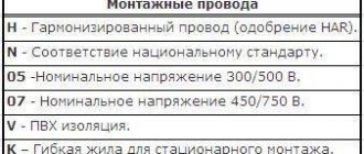
How to decipher the markings of cables and wires?
General technical conditions for power transformers are given in []. GOST includes technical requirements, safety requirements, including fire safety requirements, environmental protection requirements, operating instructions, transportation and storage. Safety requirements must also comply. According to the standard [], grounding of transformer tanks is carried out.
The degree of protection of transformers is determined by the standard []. It states that all transformers, except built-in ones, must be made with protection class 1 or 2 and have a degree of protection of at least IP20. Stationary transformers, in turn, can be manufactured with a degree of protection IP00. The system of standards [] provides requirements for transformer disposal. It describes the following series of actions:
- transformer oil should be drained and sent for regeneration;
- metal components of the transformer must be recycled;
- porcelain insulators, electrical cardboard, rubber seals must be sent to a solid waste landfill.
What does tdtn 16000/110 stand for?
Specifications
How to decipher the markings of a capacitor and find out its capacity?
Rated power of the transformer, kVA - 16,000 Rated voltage of the windings, kV: HV - 115 CH - 38.5 NN - 11 or 6.6 Winding connection diagram and group - Yn/Yn/ D-0-11 No-load current, % - 0.6 No-load loss, kW - 19 Short-circuit loss, kW - 100 Short-circuit voltage (on the main branch), %: HV-LV - 17.5 HV-MV - 10.5 MV-LV - 6.5 Weight , kg: full - 45,500 transport - 38,000 Warranty period - 5 years from the date of commissioning of the transformer.
Design and principle of operation
The transformer has a frame with a three-rod laminated magnetic system assembled from sheets of cold-rolled electrical steel. The windings of aluminum wire, cylindrical, are placed concentrically on the core rods. Linear inputs HV, MV, neutral input HV are equipped with current transformers. The transformer cooling system ensures operation using radiators. The transformer tank with a top connector is equipped with fittings for filling, sampling, draining and filtering oil, connecting the cooling system and vacuum pump. Voltage regulation under load (OLTC) is carried out by a switching device in the neutral of the HV winding within + 9 × 1.78% of the rated voltage. The transformer is manufactured: without rolling devices; with rolling devices - rotary carriages with a flange. The track for longitudinal movement is 1,524 mm, for transverse movement - 2,000 mm. The overall dimensions of the transformer are shown in the figure.
Transformers TMN, TMNP
Transformers TMN and TMNP three-phase two-winding, oil, with a power of 1000 / 1600 / 2500 / 4000 / 6300 kVA, with natural oil cooling, with voltage regulation under load (OLTC), with a regulation range of ±4 × 2.5%, used for voltage conversion in 35 kV networks.
Transformers are not designed to operate:
- in explosive and aggressive environments (containing gases, fumes, dust, high
- concentrations, etc.);
- during vibration and shaking;
- with frequent switching on from the power supply up to 10 times a day.
The TMN or TMNP transformer has a central part with a three-rod, flat-laminated magnetic system, traditionally assembled from sheets of cold-rolled electrical steel. Cylindrical layer windings made of aluminum wire are located concentrically on the core rods. The TMN transformer has HV and LV inputs. HV linear inputs are equipped with current transformers. The oil transformer tank TMN, TMNP with an upper connector is equipped with fittings for filling, sampling, draining and filtering oil, connecting the cooling system and vacuum pump. The expander is used to compensate for the thermal expansion of transformer oil. Below is a breakdown of the TMN and TMNP transformers.
Decoding TMN, TMNP
TMNP - X/35/X-X1: T - transformer; M - cooling with natural circulation of air and oil; N – voltage regulation under load (OLC) range ±4x2.5%; P - mobile type, on a skid; X – rated power, kV*A; 35 – voltage class on the HV side, kV; X – voltage class on the LV side, (6; 10) kV; X1 – climatic version (U, HL) and placement category 1;
Characteristics of the TMN transformer
| Type | Material of winding current wire | Nom. power, kVA | Nom. winding voltage, kV | Type and range of voltage regulation | Diagram and connection group | Weight (full/oil/transport), kg | Overall dimensions (length width height), mm | Transport overall dimensions (length width height), mm | Mass of oil for topping up, kg | |
| VN | NN | |||||||||
| TMN 1600/10 -U1 | copper | 1600 | 10.0 | 6.3 | On-load tap-changer in neutral VN=8 x 1.35% | Y/Δ-11 | 6500/2200/5300 | 2950 x 2350 x 2800 | 2950 x 2000 x 2770 | 650 |
| TMN 2500/10 -U1 | 2500 | OLTC in neutral VN=8 x 1.4% | 8500/2300/7200 | 3350 x 2350 x 2800 | 3050 x 2000 x 2770 | 670 | ||||
| TMN 2500/35 -U1 | 2500 | 35.0 | 6.3; 11.0 | On-load tap-changer in neutral VN=4 x 2.5% | 8300/2300/7000 | 3350 x 2350 x 2800 | 3050 x 2000 x 2770 | 670 | ||
| TMN 4000/35 -U1 | 4000 | 10600/2540/8500 | 3470 x 2390 x 3130 | 2850 x 2050 x 3100 | 880 | |||||
| TMN 6300/35 -U1 | 6300 | 15250/3500/12310 | 3660 x 2370 x 3570 | 3140 x 2000 x 3520 | 1140 | |||||
| TMN 1600/35 -U1 | aluminum | 1600 | 8385/2440/7025 | 3100 x 2300 x 2840 | 3100 x 2000 x 2310 | 660 | ||||
| TMN 2500/35 -U1 | 2500 | 8800/2440/7500 | 3100 x 2380 x 3100 | 3100 x 2070 x 3070 | 660 | |||||
| TMN 4000/35 -U1 | 4000 | 10700/3080/8550 | 3830 x 2440 x 3440 | 3850 x 1800 x 3410 | 900 | |||||
| TMN 6300/35 -U1 | 6300 | 15320/3500/13170 | 3950 x 2380 x 3670 | 3450 x 1900 x 3620 | 1150 | |||||
| TMN 10000/35 -U1 | 10000 | 6.3; 10.5 | 23500/6200/18040 | 4410 x 2750 x 4500 | 3850 x 2100 x 3330 | 2250 | ||||
Overall dimensions of TMN transformers
| Rated power of the transformer, kVA | Dimensions, mm | ||||||
| A | IN | WITH | D | E | F | G | |
| 1000 | 3000 | 1550 | 3500 | 292 | – | – | – |
| 1600 | 3350 | 2250 | 317 | ||||
| 2500 | 3600 | 3650 | 292 | 720 | 400 | 200 | |
| 4000 | 3450 | 3250 | 3700 | 317 | – | – | – |
| 6300 | 3850 | 3350 | 4000 | ||||
Characteristics of transformers TDNP, TCNP and TDTsNP
Last changes
12.08.2020
New court case No. A05-8984/2020 dated 08/12/2020 as a plaintiff, the amount of claims is 386,860 rubles.
14.06.2019
The consideration of court case No. A05-3274/2019 dated March 20, 2019 in the first instance has been completed. The organization is the plaintiff, the amount of claims is 386,860 rubles.
20.03.2019
New court case No. A05-3274/2019 dated March 20, 2019 as a plaintiff, the amount of claims is 386,860 rubles.
19.03.2019
The consideration of court case No. A05-428/2019 dated January 17, 2019 in the first instance has been completed. The organization is the plaintiff, the amount of claims is 386,860 rubles.
17.01.2019
New court case No. A05-428/2019 dated January 17, 2019 as a plaintiff, the amount of claims is 386,860 rubles.
29.12.2018
The consideration of court case No. A05-8060/2018 dated June 29, 2018 in the appellate instance has been completed. The organization is the plaintiff, the amount of claims is RUB 3,981,598,017.
27.12.2018
New government procurement as a supplier, contract No. 1121869750129010841, counterparty: FKU Ik-7 Federal Penitentiary Service of Russia for the Arkhangelsk Region
10.10.2018
The category in the Register of Small and Medium Enterprises has been changed, a new category: small enterprise
Cooling and fire extinguishing systems
As mentioned above, turbojet engines have a cooling system with natural oil circulation and forced air circulation. This means that fans are placed in mounted radiator pipe coolers. In this case, fans are placed in suspended coolers from radiator pipes. The fan draws in air from the bottom of the transformer and blows it across the heated top of the pipes.
To improve the cooling conditions of the oil, and therefore the windings of the transformer magnetic circuit, forced airflow is carried out on the radiator pipes. This makes it possible to produce transformers with split windings with a power of up to 100,000 kV•A. Currently, fans can start and stop automatically. It depends only on the heating temperature of the oil and the load [].
Decoding of TRDN and fundamental differences
TRDN is a three-phase split-winding power transformer with natural oil cooling and forced air circulation. Such models are accompanied by a load adjustment mechanism, the change is ±8 x 1.5%. The transformer is used to convert high voltage electricity to low voltage distribution.
The main difference is the presence of three windings, which make it possible to obtain voltages of 35 and 10 kV. The tank is made of an oval shape; radiators are used to improve cooling. There is a special hook for installation on the upper frame. Air circulation is started by a 0.25 kilowatt engine, which is located below the radiator. Production is regulated by state standards 11677-85 and 11920-85.
Windings of transformers TDTN, TDTNZh, TDTsTN
The winding has a control zone in the form of a separately located hub (RO winding). Voltage regulation under load is carried out in the HV neutral of the transformer in the range of + 12×1% of the nominal.
The MV winding is continuous, made of rectangular copper wire. The MV winding (38.5 kV) is made of two parallel branches with a neutral input in the middle of the winding. The control taps are routed to the bottom of the off-circuit tap switch. Voltage regulation without excitation is carried out in the range of + 2×2.5% of the nominal.
The LV winding (11 kV) is a single-pass screw, made of rectangular copper wire. The LV winding (6.6 kV) is a two-way screw, made of rectangular copper wire. The RO winding is a six-way screw, made of rectangular copper wire. The LV winding (27.5 kV) is continuous, made of rectangular copper wire. The main insulation of oil barrier type windings is made of electrical cardboard and includes upper and lower insulation and interphase partitions. HV taps are made of MG wire.
MV, LV bends, RO adjusting bends and SN adjusting bends are made with PBOT grade wire. All bends, excluding flexible connections, are insulated. HV linear bushings are oil-filled, sealed, pull-through type, voltage class 220 kV, reinforced design. The connection of the ends of the neutral and the LV taps into a triangle is provided inside the transformer. For windings of 27.5 and 38.5 kV, the taps are brought out using oil-preserving bushings of a voltage class of 35 kV, for LV windings (6.6 and 11 kV) - using oil-preserving bushings of a voltage class of 20 kV. The tank is made with a bottom connector.
For automatic control and monitoring of the cooling system, an automatic control cabinet mounted on the tank is provided. The on-load tap-changer voltage regulator is equipped with a sensor for blocking the operation of the regulator at an oil temperature below minus 25°C, as well as an automatic switching unit. Current transformers are installed at the linear inputs of HV, MV, LV (27.5 kV), and at the HV neutral. To compensate for temperature changes in the volume of oil in the transformer tank, an expander with a dial oil indicator is used.
The transformer is equipped with ladders for climbing onto the transformer and for servicing the gas relay. The tank is protected from internal pressure build-up using safety valves. The transformer is equipped with rotary carriages on rollers with flanges, with a travel track of 1524×3000 mm.
Designation of design type
Decoding of a TMN type transformer is carried out according to established standards. The marking consists of several mandatory parts. When working with transformers of various categories, maintenance personnel must understand the features of the unit.
For example, an enterprise needs to purchase a TMN-4000/35-U1 transformer. The decryption will be like this:
- T – equipment is designed to operate in a three-phase (industrial) network.
- M – oil cooling design with natural circulation.
- N – voltage regulation is carried out under load (without disconnecting from the network).
- 4000 – power, kVA.
- 35 – HV winding type, kV.
- U1 – climatic version.
A similar unit is operated in accordance with the information specified in the labeling.
Technical characteristics of TDTN, TDTNZh, TDTsTN
| Type | Rated power, kVA | Rated voltage of windings, kV | Scheme and group winding connections | Type, range and number of voltage regulation stages | Cooling | Weight, t | Length (L) x width (B) x height (H), mm installation transport | |||||
| VN | CH | NN | full | oils | oils for topping up | transport | ||||||
| TDTN-10000/110-U1 | 10000 | 115 | 16,5; 22,0 | 6,6; 11,0 | Un/D/D-11-11 | On-load tap-changer in HV neutral ± 16%, ± 9 steps; PBV on the MV side 34.5 and 38.5 kV ± (2x2.5%) | D | 50,94 | 15,4 | 2,6 | 41,3 | 6388x4691x5091 5522x2346x3690 |
| 34,5; 38,5 | Un/Un/D-0-11 | |||||||||||
| TDTN-16000/110-U1 | 16000 | 115 | 22,0 | 6,6; 11,0 | Un/D/D-11-11 | D | 52,93 | 13,81 | 2,5 | 44,19 | 6326x4617x5067 5372x2176x3565 | |
| 34,5; 38,5 | Un/Un/D-0-11 | |||||||||||
| TDTN-25000/110-U1 | 25000 | 115 | 11,0 | 6,6 | Un/D/D-11-11 | On-load tap-changer in HV neutral ± 16%, ± 9 steps | D | 66,2 | 18,75 | 3,6 | 59,31 | 6578x4752x5580 5667x2404x3768 |
| 22,0 | 6,6; 11,0 | |||||||||||
| 34,5; 38,5 | 6,3;6,6; 11,0 | Un/Un/D-0-11 | ||||||||||
| TDTNZh-25000/110-U1 | 25000 | 115 | 27,5 | 6,6; 11,0 | Un/D/D-11-11 | D | 55,5 | 13,22 | 3,8 | 47,6 | 6120x4495x5050 5350x2340x4000 | |
| TDTN-25000/110-U1(HL1) | 25000 | 115 | 11,0 | 6,6 | Un/D/D-11-11 | On-load tap-changer in HV neutral ± 16%, ± 9 steps; PBV on the MV side 34.5 and 38.5 kV ± (2x2.5%) | D | 65,13 | 18,75 | 3 | 55,31 | 6578x4752x5581 5667x2404x3768 |
| 22,0 | 6,6; 11,0 | |||||||||||
| 34,5; 38,5 | 6,3; 6,6; 11,0 | Un/Un/D-0-11 | ||||||||||
| TDTN-40000/110-U1 | 40000 | 115 | 10,5 | 6,3 | Un/D/D-11-11 | D | 85,69 | 31,36 | 4 | 75 | 6635x4885x5894 5877x2430x4274 | |
| 11,0 | 6,6 | 86,6 | 22,3 | 4,1 | 72,6 | |||||||
| 22,0 | 6,6; 11,0 | |||||||||||
| 34,5; 38,5 | 6,6; 11,0 | Un/Un/D-0-11 | ||||||||||
| TDTNZh-40000/110-U1 | 40000 | 115 | 27,5 | 6,6; 11,0 | Un/D/D-11-11 | On-load tap-changer in HV neutral ± 16%, ± 9 steps | D | 72,8 | 17,5 | 1,42 | 61 | 6432x5055x6010 5543x2400x4420 |
| TDTN-63000/110-U1 | 63000 | 115 | 11,0 | 6,6 | Un/D/D/-11-11 | On-load tap-changer in HV neutral ± 16%, ± 9 steps; PBV on the MV side 34.5 and 38.5 kV ± (2x2.5%) | D | 109,4 | 27,4 | 5,0 | 90,0 | 7400x5900x6700 6150x2525x4250 |
| 38,5 | 6,6; 11,0 | Un/Un/D-0-11 | ||||||||||
| TDTsTN-63000/110-U1 | 63000 | 115 | 34,5 | 6,6; 11,0 | Un/Un/D-0-11 | DC | 114,8 | 25,71 | 3,9 | 105 | 6680x3688x6245 6150x2520x4220 | |
| TDTN-80000/110-U1 | 80000 | 115 | 38,5 | 6,6; 11,0 | Un/Un/D-0-11 | D | 123,4 | 29,7 | 6,56 | 103 | 8500x5000x6600 6300x2670x4180 | |
| TDTsTN-80000/110-U1 | 80000 | 115 | 11,0 | 6,6; 6,94 | Un/D/D-11-11 | On-load tap-changer in HV neutral ± 16%, ± 9 steps | DC | 125,81 | 30,24 | 3,41 | 112,4 | 8250x4647x7202 6381x2746x4587 |
| 22,0; 38,5 | 11,0 | Un/Un/D-0-11 | ||||||||||
| TDTsTN-100000/220-U1 | 100000/ 83000/ 100000 | 230 | 22,0 | 11,0 | Un/Un/D-0-11 | On-load tap-changer in HV neutral ± 8x1.5%; PBB on the CH side ± 2x2.5% | DC | 163,8 | 42,0 | 12,0 | 123,6 | 8755x6436x8940 7820x3157x4275 |
| TDTsTN- 125000/220-U1 | 125000/ 83000/ 125000 | 230 | 22,0 | 11,0 | Un/Un/D-0-11 | DC | 192,7 | 51,5 | 7,15 | 171 | 8870x5400x7900 8550x3288x4290 |
Characteristics of TMN 6300/110/6
- Characteristics
- Dimensions
- Weight
| Transformer type | TMN |
| Rated power Sn, MVA | 6,3 |
| Number of windings and type | Double winding transformer |
| HV side network voltage Unom. network, kV | 110 |
| HV winding voltage Uin, kV | 115 |
| MV winding voltage Uсн, kV | — |
| LV winding voltage Unnn, kV | 6,6 |
| No-load losses ΔPxx, kW | 10 |
| Short circuit losses ΔPsc, kW | 44 |
| Voltage Ukv-n, % | 10,5 |
| Current Ixx, % | 1 |
| Oil, t | 10,5 |
| Transportation, t | 24,5 |
| Full, t | 28,4 |
| Length, m | 5,8 |
| Width, m | 4,2 |
| Height, m | 5 |
Double-winding transformers TDNS 10000\35 U1
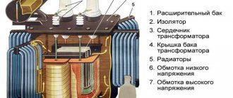
| 1. Transformer tank | 6. Radiator | Name | Weight, kg |
| 2. Expander | 7. On-load tap-changer | Oil to be topped up | 1800 |
| 3. Enter “0”VN | 8. Wardrobe | Transport with oil | 22000 |
| 4. HV input | 9. Thermosyphon filter | Total oil weight | 7000 |
| 5. LV input | 10. Buchholz relay | Full mass | 26000 |
Three-phase, two-winding power oil transformer with voltage regulation under load, type TDNS-10000/35-U1, UHL1, voltage class 35 kV, designed for operation in electrical networks and in complete transformer substations.
Technical characteristics and decoding of TDNS 10000\35 U1
TDNS-10000/35-U1, UHL1: T - three-phase transformer; D - forced air circulation and natural oil circulation; N - voltage regulation under load; C - design of the transformer for the auxiliary needs of power plants; 10000 — rated power, kVA; 35 — voltage class of the HV winding, kV; U1, UHL1 - climatic version and placement category according to GOST 15150-69.
terms of Use
Altitude above sea level no more than 1000 m. Ambient temperature from minus 45 to 40°C. The environment is non-explosive and does not contain conductive dust, gases and vapors in concentrations that destroy metals and insulation. Safety transformers comply with GOST 12.2.007.2-75 and are manufactured in accordance with GOST 11677-85 and GOST 11920-85. GOST 11677-85; GOST 11920-85
- Rated power, kVA - 10000
- Rated frequency, Hz - 50
- Winding voltage, kV: VN - 35; 36.75 NN - 6.3; 11.0
- Winding connection diagram and group - Un/D-11
- Short circuit voltage on the main branch, % - 8
- Losses, kW: idling - 12
- short circuit - 60
- No-load current,% - 0.75
- HV voltage regulation limits, % - +8×1.5 Weight, kg:
- active part - 12300
- transformer oil - 7000
- transport - 22000
- full - 26000
- The warranty period is 3 years from the date of commissioning of the transformer.
Design and principle of operation
The transformer includes the following components: core, windings, main insulation, taps, voltage regulation device, tank, cooling system, protective devices, bushings. The core of the transformer consists of vertical rods covered at the top and bottom with yokes, forming a closed three-phase magnetic circuit. The lamination of the magnetic system plates is carried out according to the scheme with a full oblique joint on the outer rods and a combined joint on the middle rod. The rods are tied using pressing plates and one-piece bandages made of glass tape, yokes - with yoke beams and metal half-bandages. The windings are cylindrical, made of rectangular wire of the APB brand and are located concentrically on the core rod in the following order, counting from the rod: NN, VN, RO.
The insulation is low-barrier type, electrical cardboard alternates with an oil gap. An expander, “O” HV, LV, HV inputs, TVT-35 kV units, and a gas exhaust system are installed on the tank cover. The transformer tank is welded, with a top connector. To move within the substation, the transformer is equipped with carriages with rollers. The track for longitudinal and transverse movement is 1524 mm.
The transformer cooling system consists of radiators, an automatic blowing control cabinet, and an electric motor for blowing fans. The transformer is equipped with a ladder for servicing the gas relay. Maximum deviations of installation dimensions correspond to RD 16 20 1.05-88
Rate this article:
Structure of the symbol (Decoding)
TMN - Х/10 У(ХЛ)1 - Х Т – three-phase transformer, М – oil cooling with natural circulation of air and oil, Н – voltage regulation under load Х – rated power, kVA, 35 – voltage class of the HV winding, kV, U(HL)1 – climatic version and placement category according to GOST 15150-69; X is the level of no-load and short circuit losses. Operating conditions Altitude above sea level - up to 1000 m. Ambient air temperature: - for temperate climates - from –45°C to +40°C (version “U”); — for cold climates — from –60°C to +40°C (“HL” version). Relative air humidity – no more than 80% at +25 °C.