How to find out the power of a toroidal transformer by dimensions
There was a need for a powerful power supply. In my case, there are two magnetic cores: armored tape and toroidal. Armor type: ШЛ32х50(72х18). Toroidal type: OL70/110-60.
INITIAL DATA for calculating a transformer with a toroidal magnetic core:
- primary winding voltage, U1 = 220 V;
- secondary winding voltage, U2 = 36 V;
- secondary winding current, l2 = 4 A;
- core outer diameter, D = 110 mm;
- core inner diameter, d = 68 mm;
- core height, h = 60 mm.
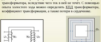
Calculation of a transformer with a magnetic core type ШЛ32х50 (72х18) showed that the core itself is capable of producing a voltage of 36 volts with a current strength of 4 amperes, but it may not be possible to wind the secondary winding due to insufficient window area. Let's start calculating a transformer with a magnetic core of type OL70/110-60.
Software (on-line) calculation will allow you to experiment with parameters on the fly and reduce development time. You can also calculate using the formulas, they are given below. Description of the input and calculated fields of the program: a light blue field - the initial data for calculation, a yellow field - data selected automatically from the tables, if you check the box to adjust these values, the field changes color to light blue and allows you to enter your own values, green field – calculated value.
Formulas and tables for manual calculation of a transformer:
1. Secondary winding power;
2. Overall power of the transformer;
| Magnitude | Total power of secondary windings Pout, [W] | ||||
| 2-15 | 15-50 | 50-150 | 150-300 | 300-1000 | |
| Efficiency | 0,76-0,88 | 0,88-0,92 | 0,92-0,95 | 0,95-0,96 | |
3. The actual cross-section of the steel of the magnetic core at the location of the transformer coil;
4. The calculated cross-section of the magnetic core steel at the location of the transformer coil;
5. Actual cross-sectional area of the core window;
6. The value of the rated current of the primary winding;
| Magnitude | Total power of secondary windings Pout, [W] | ||||
| 2-15 | 15-50 | 50-150 | 150-300 | 300-1000 | |
| COS Φ | 0,85-0,90 | 0,90-0,93 | 0,93-0,95 | 0,95-0,93 | 0,93-0,94 |
7. Calculation of the wire cross-section for each of the windings (for I1 and I2);
| Magnetic core design | Current density J, [A/mm sq.] at Pout, [W] | ||||
| 2-15 | 15-50 | 50-150 | 150-300 | 300-1000 | |
| Ring | 5-4,5 | 4,5-3,5 | 3,5 | 3,0 | |
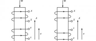
Toroidal transformer and its calculation
In order to greatly facilitate the calculation of a toroidal transformer, you need to know the following data:
- The output voltage that will be supplied to the primary winding U.
- External core diameter D.
- Core inner diameter d.
- Magnetic core
The cross-sectional area S will determine the power of the transformer. The optimal value today is considered to be 45-50 cm. Calculating this value is quite simple and can be done using the formula:
The most important characteristic of the core is the area of its window S. This parameter will determine the intensity of excess heat removal. The optimal value of this parameter can be 80-100 cm. It is calculated using the formula:
Read also: How to calculate the cross-section of a conductor
Thanks to these values, you can easily calculate its power using the formula:
P = 1.9 * Sc * S, where Sc and S must be taken in square centimeters, and P will be obtained in watts. Then you will need to find the number of turns per volt:
Once the value of k becomes known to you, you can calculate the number of turns in the secondary winding:
It is better to make calculations if you use the voltage on the secondary winding as the initial value:
W1 = (U1 * w2) / U2, where U1 is the voltage that is supplied to the primary winding, and U2 is removed from the secondary.
The easiest way to regulate the welding current is by changing the number of turns in the primary winding, since there is less voltage here.
How to find out the power of a toroidal transformer by dimensions
Currently, the most common types of magnetic cores are:
In some places you can still find W-shaped plate cores; the calculation of such transformers is similar to the calculation of W-shaped strip ones.
The toroidal transformer can be used at powers from 30 to 1000 W when minimal flux leakage is required or when minimum volume requirement is paramount. Having some advantages in volume and weight over other types of transformer designs, toroidal ones are at the same time the least technologically advanced (convenient) to manufacture.
How to specify the number of turns of the primary winding?
Knowing the number of turns of the primary winding n
Let's calculate its inductance. For a toroid it is determined by the formula:
L = μ 0 μ S with n 2 / la
(5)
Where is the area S with
given in m 2, the average length of the magnetic line
la
in m, inductance in H,
μ 0 = 4π ⋅ 10 -7
H/m - magnetic constant.
In the engineering version, this formula looks like this:
L = AL n 2
(5A) ,
n = (L / AL) 1/2
(5B)
AL coefficient
and the power parameter
S o S c
for some types of rings are given in Table 2:
For the transformer to operate as a matching device, the following condition must be met:
L > (4 .. 10) R / (2 π f min)
(6)
Where L
- inductance in H,
R = U 2 eff / P n
load resistance reduced to the primary winding Ohm,
f min
- minimum frequency Hz.
In key converters, two currents flow in the primary winding, rectangular load current I pr = U m / R
and triangular magnetizing current $$ I_T= {1 \over L} \int_0^{T/2} U_1 dt = { T \over 2L }U_m $$
For normal operation, the value of the triangular component should not exceed 10% of the rectangular component, i.e.
L>5 R/f (7)
If necessary, increase the number of turns or use ferrite with a higher μ
.
It is not advisable to overestimate the number of turns in the winding. Due to the increase in interturn capacitance, resonant oscillations may occur at the operating frequency. The selected ferrite must have sufficient maximum induction and low losses in the operating frequency band. As a rule, at low frequencies (up to 1 MHz) ferrite with μ
= 1000 .. 6000 is used, and at radio frequencies it is necessary to use
μ
= 50 .. 400.
Example 2:
The transformer from Example 1 is wound on a K28x16x9 ring made of 2000NM nickel-manganese ferrite with magnetic permeability μ
= 2000. Load power P = 40 W, effective voltage of the primary winding Ueff = 100 V, frequency f = 30 kHz. Let's clarify the number of its turns.
Reduced load resistance: R = 100 2 / 40 = 250 Ohm
Cross-sectional area of the magnetic circuit:
Sc = 0.54 cm 2 = 0.54 ⋅ 10 -4 m 2
Average length of the magnetic line:
la = π (D + d) / 2 = π (2.8+1.6) ⋅10 -2 / 2 = 6.9 ⋅ 10 -2 m
Inductance coefficient:
AL = 4 π 10 -7 2000 0.54 10 -4 / 6.9 10 -2 = 1963 nH / vit 2
Minimum primary winding inductance: L = 10 ⋅ 250 / (2π ⋅ 3 ⋅ 10 4) = 13.3 mH
Number of turns:
n = (13.3 ⋅ 10 -3 / 1.963 ⋅ 10 -6) 1/2 = 82
It is even less than the previously calculated
n min = 87.
Thus, the condition of sufficient inductance is met and the number of turns in the winding is n = 87.
Principle of operation
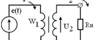
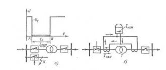
The main feature of pulse-type transformers (hereinafter referred to as IT) is that they are supplied with unipolar pulses with a constant current component, and therefore the magnetic circuit is in a state of constant magnetization. Below is a schematic diagram of connecting such a device.
Diagram: connecting a pulse transformer
As you can see, the connection diagram is almost identical to conventional transformers, which cannot be said about the timing diagram.
The primary winding receives pulse signals having a rectangular shape e (t), the time interval between which is quite short. This causes the inductance to increase during the interval tu, after which its decline is observed in the interval (T-tu).
Induction changes occur at a speed that can be expressed in terms of a time constant using the formula: τ p =L 0 /R n
The coefficient describing the difference in the inductive differential is determined as follows: ∆V=V max – V r
- В max – level of maximum induction value;
- In r – residual.
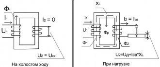
The difference in induction is shown more clearly in the figure, which shows the displacement of the operating point in the magnetic conductor circuit of the IT.
As can be seen in the timing diagram, the secondary coil has a voltage level U 2 in which reverse emissions are present. This is how the energy accumulated in the magnetic circuit manifests itself, which depends on magnetization (parameter iu).
The current pulses passing through the primary coil are trapezoidal in shape, since the load and linear currents (caused by the magnetization of the core) are combined.
The voltage level in the range from 0 to tu remains unchanged, its value e t =U m. As for the voltage on the secondary coil, it can be calculated using the formula:
wherein:
- Ψ – flux linkage parameter;
- S is a value that reflects the cross-section of the magnetic core.
Considering that the derivative, which characterizes changes in the current passing through the primary coil, is a constant value, the increase in the induction level in the magnetic circuit occurs linearly. Based on this, it is permissible, instead of the derivative, to enter the difference between the indicators taken over a certain time interval, which allows you to make changes to the formula:
in this case, ∆t will be identified with the parameter tu, which characterizes the duration with which the input voltage pulse occurs.
To calculate the area of the pulse with which the voltage is generated in the secondary winding of the IT, it is necessary to multiply both parts of the previous formula by tu. As a result, we arrive at an expression that allows us to obtain the main IT parameter:
U mxtu =S x W 1 x ∆V
Note that the magnitude of the pulse area directly depends on the parameter ∆B.
The second most important quantity characterizing the operation of IT is the induction drop; it is influenced by such parameters as the cross-section and magnetic permeability of the magnetic core, as well as the number of turns on the coil:
Here:
- L 0 – induction difference;
- µ a – magnetic permeability of the core;
- W 1 – number of turns of the primary winding;
- S – cross-sectional area of the core;
- l cр – length (perimeter) of the core (magnetic core)
- In r – the value of residual induction;
- In max – the level of the maximum induction value.
- H m – Magnetic field strength (maximum).
Considering that the inductance parameter of the IT completely depends on the magnetic permeability of the core, when calculating it is necessary to proceed from the maximum value of µ a, which is shown by the magnetization curve. Accordingly, for the material from which the core is made, the level of the parameter B r, which reflects the residual induction, should be minimal.
Video: detailed description of the operating principle of a pulse transformer
Based on this, a tape made of transformer steel is ideal as an IT core material. You can also use permalloy, which has a minimum squareness coefficient.
Cores made of ferrite alloys are ideal for high-frequency IT, since this material has low dynamic losses. But due to its low inductance, IT has to be made in large sizes.
Typical parameter calculation
Quite often, radio amateurs use a simplified method when calculating a transformer. It allows you to perform calculations at home without using quantities that are difficult to know. But it’s easier to use an online calculator ready for calculating a transformer. In order to use such a calculator, you will need to know some data, namely:
- voltage of the primary and secondary windings;
- core dimensions;
- plate thickness.
After entering them, you will need to click the “Calculate” button or something similar in name and wait for the result.
Rod type magnetic core
If it is not possible to calculate on a calculator, performing such an operation yourself is not difficult and manually. To do this, you will need to determine the voltage at the output of the secondary winding U2 and the required power Po. The calculation proceeds as follows:
- The load current is calculated: In=Po/U2, A.
- The value of the secondary winding current is calculated: I2 = 1.5*In, A.
- The power of the secondary winding is determined: P2 = U2*I2, W.
- The total power of the device is found: Pt = 1.25*P2, W.
- The current strength of the primary winding is calculated: I1 = Pt/U1, A.
- The required cross-section of the magnetic circuit is found: S = 1.3*√ Pt, cm².
It should be noted that if a device is designed with several terminals in the secondary winding, then in the fourth point all powers are summed up and their result is substituted instead of P2.
After the first stage is completed, proceed to the next stage of calculation. The number of turns in the primary winding is determined by the formula: K1 = 50*U1/S. And the number of turns of the secondary winding is determined by the expression K2= 55* U2/S, where:
- U1 - voltage of the primary winding, V.
- S—core area, cm².
- K1, K2 - number of turns in windings, pcs.
It remains to calculate the diameter of the wound wire. It is equal to D = 0.632*√ I, where:
- d — wire diameter, mm.
- I is the winding current of the calculated coil, A.
When selecting a magnetic core, you should maintain a ratio of 1 to 2 of the width of the core to its thickness. At the end of the calculation, the fillability is checked, i.e. whether the winding will fit on the frame. To do this, the window area is calculated using the formula: So = 50*Pt, mm2.
Autotransformer Features
Autotransformers are calculated similarly to simple transformers, only the core is determined not for the entire power, but for the power of the voltage difference.
For example, the power of the magnetic circuit is 250 W, the input is 220 volts, and the output needs to be 240 volts. The voltage difference is 20 V, with a power of 250 W the current will be 12.5 A. This current value corresponds to a power of 12.5 * 240 = 3000 W. The mains current consumption is 12.5+250/220=13.64A, which exactly corresponds to 3000W=220V*13.64A. The transformer has one 240 V winding with a 220 V tap, which is connected to the network. The section between the outlet and the outlet is wound with a wire rated at 12.5A.
Thus, an autotransformer allows you to obtain significantly more output power than a transformer with the same core with a low transmission coefficient.
Toroidal type transformer
Toroidal transformers have a number of advantages over other types: smaller size, lighter weight and, at the same time, higher efficiency. At the same time, they are easily wound and rewound. Using an online calculator to calculate a toroidal transformer allows you not only to reduce the manufacturing time of the product, but also to experiment on the fly with different input data. The following data is used:
- input winding voltage, V;
- output winding voltage, V;
- output winding current, A;
- outer diameter of the torus, mm;
- internal diameter of the torus, mm;
- torus height, mm.
It should be noted that almost all online programs do not demonstrate particular accuracy when calculating pulse transformers. To obtain high accuracy, you can use specially developed programs, for example, Lite-CalcIT, or calculate manually. For independent calculations, use the following formulas:
- Output winding power: P2=I2*U2, W.
- Overall power: Pg=P2/Q, W. Where Q is the coefficient taken from the reference book (0.76−0.96).
- The actual cross-section of the “iron” at the location of the coil: Sch= ((Dd)*h)/2, mm2.
- Calculated cross-section of the “iron” at the location of the coil: Sw =√Pq/1.2, mm2
- Torus window area: Sfh=d*s* π/4, mm2.
- The value of the operating current of the input winding: I1=P2/(U1*Q*cosφ), A, where cosφ is a reference value (from 0.85 to 0.94).
- The wire cross-section is found separately for each winding from the expression: Sp = I/J, mm2., where J is the current density taken from the reference book (from 3 to 5).
- The number of turns in the windings is calculated separately for each coil: Wn=45*Un*(1-Y/100)/Bm* Sch pcs., where Y is a table value that depends on the total power of the output windings.
- It remains to find the output power and the calculation of the toroidal power transformer is considered completed. Pout = Bm*J*Kok*Kct* Sch* Sfh /0.901, where: Bm - magnetic induction, Kok - wire filling coefficient, Kct - iron filling coefficient.
All coefficient values are taken from the radio equipment reference book (REA). Thus, it is not difficult to carry out calculations manually, but you will need accuracy and access to reference data, so it is much easier to use online services.