The concept of magnetizing current
The sudden increase, that is, the inrush of the magnetizing current (BCT), is explained by the saturation of the core by magnetic induction. Transformers are dynamically resistant to surges due to the manufacture of windings taking into account large currents, as a rule, arising from short circuits. On average, the magnetizing current exceeds the rated value of the device by 6-8 times.
Rice. 1. Conditions for the appearance of BTN
In short circuit mode, the voltage of the power unit is characterized by an extreme decrease to zero, and after disconnecting the damage zone, it is established at the terminals of the device in an abrupt manner.
The restoration of the magnetic flux occurs unevenly and not immediately, which causes the occurrence of a transient process, during which two fluxes are formed - a steady FU and a free FSV. To determine the total value, the formula is used:
FTO = FU + FSV
At the reference point, which characterizes the initial moment of time at t = 0, the FTO is also equal to zero, so the equality FSV = – FU seems fair. The signs of the polarity of magnetic fluxes coincide in the second half-cycle, and, accordingly, the resulting value reaches a peak maximum (FTmax).
Rice. 2. Magnetic fluxes in the core under load
Schematically, there is a lag of FU from UT by 90 degrees, which indicates the dependence of FSV and FTmax on the voltage phase. These values reach their highest values when turned on - at the moment UT passes through zero. If we do not take into account gradual attenuation, FTmax ≈ 2FU. But the peak flux value can be higher when there is residual magnetization Fost in the core thickness, which coincides in sign with FSV.
Then:
FTmax = (2FU + Fost)> 2FU
The core is saturated at flux values close to 2FU, causing a sharp surge in In. The magnetizing current is generated only in the winding of the circuit to which voltage is applied when turned on. It is converted through a protective device and enters the relay, causing it to operate subject to the inequality Iam > Is.z..
Transformer magnetization
The dependence of Ф and I0р is nonlinear due to core saturation. Therefore, with a sinusoidal change in one quantity, the other will change non-sinusoidally.
1 Homogeneous transformer. Connected to sinusoidal voltage. The magnetic flux is proportional to the voltage and will also be sinusoidal. The shape of the magnetizing current I0р is determined graphically.
The first square shows the relationship between the instantaneous values of the magnetic flux and the magnetizing component of the no-load current Ф = f (iop) - this relationship is called the magnetic characteristic. In the second square there is a sinusoidal curve Ф = f (t), where t is time. If for individual moments of time the values of Ф along the curve Ф = f (t) are transferred to the curve Ф = f (iop). and then transfer the values obtained for the same moments of time downwards, then we obtain the shape of the current curve iop = f (t) - the resulting curve is non-sinusoidal, it has a pointed character. If the function iop= f (t) is expanded into a harmonic series, it will contain only odd harmonics (1, 3 5 ...). The most pronounced third harmonic is the amplitude of which in transformers is up to 50% of the amplitude of the first. The amplitude of the harmonics depends on the saturation of the core: the stronger the saturation, the greater the amplitude of the higher harmonics.
In addition to the first, the current I0р contains higher harmonics:
The active component of the current XX ioa is sinusoidal. The resulting i0 curve will have some asymmetrical relative to the vertical.
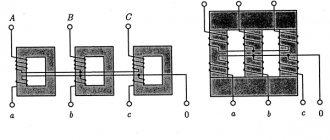
2 Three-phase transformers
The manifestation of higher harmonics in the magnetizing component of the current I0p and the magnetic flux of three-phase transformers depends on the connection diagrams of the primary and secondary windings.
Case 1 Both windings are connected in a star. Linear voltages are sinusoidal. The first harmonic currents are shifted in phase by an angle of 120°, the third harmonic currents are shifted by an angle of 3-120° = 360°, i.e. they will coincide for all phases and balance each other. Therefore, in the magnetizing current there will be no harmonics that are multiples of 3, 5 and 7; the harmonics are very small, therefore the current I0p is close to sinusoidal. With this shape of I0p, the flow curve will have a non-sinusoidal shape. The harmonic components of the flux will induce EMF in the windings of the transformer, shifted from the corresponding flux by an angle π/2. The shape of the resulting EMF is distorted. The induced emf is proportional to the flux and frequency. The frequency of the third harmonic is three times the frequency of the first harmonic. Therefore, the amplitude ratio will be three times greater than the flow amplitude ratio.
Therefore, the increase in EMF can be significant, which will lead to an increase in the electric field strength in the insulation. At the same time, the attitude
The Y/Y connection in three-phase transformers does not change
Case 2 The primary winding is connected in a triangle, the secondary in a star. Each phase of the primary winding is connected to a sinusoidal mains voltage. Consequently, the phase flows will also be sinusoidal, and the magnetizing components of the phase current will contain odd higher harmonics. Since the third harmonics of the currents in all phases have the same voltage, they will circulate inside the triangle. The magnetizing component of the linear current will not contain third harmonics, since they cancel each other during subtraction. (Il = Ifa - Iab)
Case 3 The primary winding is connected in a star, the secondary in a delta. There will be no third harmonics in the magnetizing current and it will be sinusoidal.
The third harmonics of the flow are in all phases in amplitude and coincide in phase. They will induce in the secondary windings three equal in magnitude and identical in phase emfs E2(3). Adding up in the triangle circuit, these EMFs create a current I2(3) in this circuit
Third harmonic currents in the secondary winding of the transformer
The current I2(3) has triple the frequency L lags behind the EMF E2(3) by an angle l/2, since the inductive resistances of the windings are much greater than their active resistances. Current I2(3) forms a flux Ф, which is directed towards the flow Ф3 and almost completely compensates for it (see figure)
Therefore, with such a connection of the windings, the magnetic flux will be sinusoidal.
When one of the transformer windings is connected according to the Un circuit (zero current is output), a circuit is also formed to close the third harmonic currents. These currents flow in the linear wires and 2/3 of the load or line capacity is closed by 2/3 of the neutral wire. The third harmonic currents of all three phases will flow in the neutral wire. Passing along the line, these currents can create electricity. mg. Interference in adjacent wire lines. Load resistance and
capacitors included in the circuit reduce the third harmonic current and weaken its influence.
When the transformer is magnetized, when it is turned on and the network is on, noise is observed during its operation (humming). The reason for this is a change in the dimensions of steel sheets and the magnetic circuit as a whole during magnetization in an alternating magnetic flux - this phenomenon is called magnetostriccycle. (The fundamental frequency of magnetostrictive noise is equal to twice the magnetizing frequency.)
When one of the transformation windings is connected according to the Un circuit, a circuit is also formed to close the third harmonic current through the neutral wire.
Why does the surge occur when turned on?
A short-term jump is characterized by an inrush of the magnetizing current of the transformer (BTC). Its values on the same device may differ in value for different switching ons. The reason for the formation of BTN in power devices is a sudden change in the magnetizing voltage level. In addition to the load transferred to the winding, the surge can be caused by other reasons:
- external short circuit (SC);
- restoration of voltage in the circuit;
- short circuit transformation;
- non-synchronous connection of the generator.
The magnetizing current introduces an imbalance at the transformer terminals. The device protection perceives the BTN as a differential current. But in order for it to correctly fulfill its purpose, the system must function effectively and be configured taking into account the BTN by including auxiliary devices such as intermediate transformers in the circuit.
To prevent surges from affecting the operational life of the unit, it is undesirable to allow the transformer to turn off as a result of surges.
When the winding is turned on at full load, due to asynchronous power distribution and transient wave processes, a high overvoltage occurs, which can cause an internal short circuit.
Important! Overvoltages due to BTN are safe only if the differential protection of the system is properly organized.
How the process works
When a load is applied, the magnetization of the device due to switching on is considered as a negative phenomenon that can provoke a BTN of maximum amplitude. When turned off, the magnetizing current is reduced to zero, and the magnetic induction is adjusted depending on the degree of magnetization of the steel core, as a result of which residual induction remains in the magnetic circuit.
If after a while the current-converting device is switched on again under a voltage subject to the sinusoidal law of change, the magnetic induction changes with a displacement of the residual value up to 90% of the nominal value. The result is a high magnetization amplitude and a change in the shape of the curve.
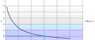
Rice. 3. Classic type BNT curve
The magnetizing current level decays within tenths of a second, but complete “smoothing” of the curve occurs within a few seconds, and under certain conditions – after a few minutes. The duration of attenuation of the aperiodic component of the BTN oscillogram is due to the high amplitude of the current at the initial (zero) moment of time and the content of various harmonics. The peak value depends on the load voltage and its parameters, as well as on the value and polarity of the residual magnetic flux in the core.
The peak current can be 10-15 times higher than the rated value for high-power units, and 20-25 times higher for devices with power (<50 kVA). The decay period ranges from a few milliseconds to seconds.
Single phase transformer
When the transformer is no-load, the equation for the primary voltage is valid:
that is, the voltage u is spent on the voltage drop r × i and balancing the electromotive force (emf)
If we neglect the insignificant voltage drop r × i, then
Therefore, if the voltage is sinusoidal:
u = Um × sinωt,
then the flow Ф should also change according to a sinusoidal law:
Ф = Фm × sin (ωt – π/2) .
Let us first also neglect steel losses. Then the no-load current i = i0 consumed from the network is a purely reactive magnetizing current (i = i0r).
The flow Ф is created by the current i0r. Since in the presence of saturation the proportionality between Ф and i0r is violated, then with a sinusoidal flow Ф the current i0r will no longer be sinusoidal.
| Figure 1. Determination of the reactive component of the magnetizing current of a single-phase transformer |
In Figure 1, the right quadrant shows the curve Ф = f(i0r) in the presence of saturation, and the left quadrant shows the sinusoidal curve Ф = f(t), where t is time. The lower quadrant of this figure shows the curve i0r = f(t), which can be obtained, as shown in the figure, if the values of Ф along the curve Ф = f(t) for individual moments of time 1, 2, 3 and so on are transferred to the curve Ф = f(i0r) and the resulting values of i0r are brought down and set aside for the same moments of time. The negative half-wave of the curve i0r = f(t) will have the same shape as the positive one. Such a non-sinusoidal curve i0r = f(t) (Figure 2) contains all odd harmonics (v = 1, 3, 5...), of which, along with the first, or fundamental (v = 1), the third harmonic will be the strongest. For steel grade 15... and a maximum induction of 1.4 T, the third harmonic is about 30%, and the fifth is about 15% of the fundamental.
| Figure 2. Harmonics of the magnetizing current of a single-phase transformer |
In addition to the reactive component i0r, the no-load current i0 also contains a relatively small active component i0a, which is sinusoidal and caused by magnetic losses in the magnetic circuit (Figure 2). The total magnetizing current i0 = i0a + i0r has an asymmetrical shape.
Methods of blocking on the secondary winding
There are several ways to eliminate false positives on BTN. The effectiveness of the method of slowing down protection (disadvantage - loss of performance), braking, blocking, which did not give good results, was experimentally tested. The most rational methods of detuning from magnetizing currents are:
- Use of fast-saturating transformers.
- Adjustment of differential cutoff.
The methods have proven their effectiveness in practice, are distinguished by high reliability, simplicity and preservation of the most important protection parameter - speed.