Causes of sparks and arcs
Before we look at why contacts spark, let's understand the basic concepts. The switching device and its contact system must provide a reliable connection with the possibility of breaking it at any time. The contacts consist of two electrical plates, which in the closed position must be securely pressed against each other.
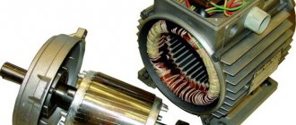
An arc occurs when switching inductive circuits. These include various electric motors and solenoids, but it is worth remembering that even a straight piece of wire has a certain inductance, and the longer it is, the greater it is. At the same time, the current in the inductance cannot stop instantly - this is described in the laws of commutation. Therefore, a self-inductive emf is formed at the terminals of the inductive load, its value is described by the formula:
E=L*dI/dt
Interesting! In our case, the rate of change of current plays an important role. When turned off, it is extremely high, and accordingly the EMF will tend to large values, up to tens of kilovolts (for example, a car ignition system).
As a result, the EMF increases to such an extent that its value breaks the gap between the contacts - an electric arc or spark is formed. The quality of any connections is described by their contact resistance: the lower, the better the connection and the less heating. When they open, it increases sharply and tends to infinity. At the same moment, the area of their contact heats up.
In addition, between the open contacts against the background of increasing self-induction EMF and increased air temperature due to heating of the surfaces when the plates are opened, air ionization occurs. As a result, all the conditions for arcing and sparking are present.
If we talk about why contacts spark when an electrical circuit is closed, then this happens not with an inductive load, but with a capacitive load. You see this every time you plug in your laptop or phone charger. The fact is that the discharged capacitance (capacitor) at the input of the device at the initial moment of time represents a short-circuited section of the circuit, the current of which decreases as it is charged.
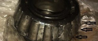
If you observe sparking in a relay or switch in the closed position, the reason for this is the poor condition of the contact surfaces and their high contact resistance.
How the voltage relay caused the fire.
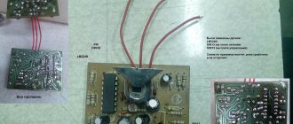
Hi all! Today outside the window there is “frost and sun, a wonderful day...”, but the mood is not very good. I want to tell you why. In this article I will describe an incident that happened today in my country house, as it is directly related to construction, namely, electrics. Today in one of the rooms there was a spontaneous combustion of one device in the panel, which is called a voltage relay PH-113 . So what is this relay?
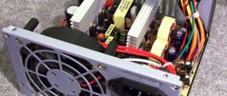
As stated on the manufacturer’s website (see screenshot above), this relay is designed to disconnect household and industrial single-phase loads of 220 V, 50 Hz in the event of unacceptable voltage fluctuations in the network, followed by automatic activation after the network parameters are restored. Think about it, household and industrial ... That is, it is reliable. It was recommended to me as a high-quality relay. In addition, the product data sheet generally states that this device belongs to the category of intelligent industrial electronics (see photo below).
In addition, the company itself declares itself as a manufacturer that fights for the quality of its own products (see screenshot below).
Now let's see what happened to this intelligent, nanotechnological, industrial device. Here it must be said that the device was connected to a single-phase network with a 25A input circuit breaker. The device states that it is rated at 7 kW.
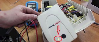
or like this, with a flash..
Here's a side view below...
A very sad look for a high-quality high-tech device. This photo clearly shows that the source of the fire is (was) inside, which indicates that the cause of the fire is the device itself, and not external factors. By the way, I was very lucky that I was at home at the time of the fire and managed to react literally within a minute so that even the insulation on the wires did not have time to melt, otherwise the house could have burned down. In general, once again our domestic manufacturer rose to the occasion and was very bright (the flame was quite large) and convincingly proved that if you need a reliable electrical appliance, spare no expense, buy Legrand or ABB. Don't take risks. Don't save money. Houses and apartments and their repairs are more expensive. For reference, this device was installed about half a year ago, for another half a year it was lying on the shelf, I didn’t want to install it, apparently my intuition told me that it wasn’t necessary. But then I installed it anyway. In vain. I'm sorry. By the way, this is the place where the device was installed.
Well, the counter and the backup power input switching relay did not burn out. In conclusion, I would like to ask readers who have encountered a similar problem, are especially interested in products, describe the situation in the comments or send information to me by email (see the “Contacts” section). Preferably with photographs. We will create a black list of products and companies.
Consequences of sparking
Due to sparking, metal evaporates from the contacts, heating them up and increasing the contact resistance. The latter causes them to burn even more, after which they spark even more. The consequences of these processes can lead to a partial or complete lack of switching ability of the device, even to the point of sticking or fire under certain circumstances. It is necessary to monitor the condition of all connections and moving switching elements.
Ways to eliminate and prevent the phenomenon
To eliminate sparking of contacts, decisions are made at the stage of development of switching devices. For example, the distance between them increases, arc suppression chambers are installed to cool the arc.
They also make solderings from precious non-oxidizing materials, such as silver, for example, on surfaces through which current passes.
On high-speed relays, sparking occurs when opening, including because their contacts in the open position are close to each other. This means you need to reduce the load by using intermediate relays or using spark-extinguishing circuits; we will consider their circuits further.
Protecting relay contacts from burning
Automotive relays
Automotive electro-mechanical relays are used in automotive automation devices.
Subminiature relays
Subminiature electromechanical relays are mounted on a printed circuit board, serve for switching low currents (up to 2A), and are used in telecommunication signal circuits.
Miniature relays with DC coil
Miniature general purpose electrical relays are used primarily in DC circuits, switch currents up to 16A, and are mounted both on DIN rails and on a printed circuit board
Miniature relays with AC/DC coil
Miniature relays are used in both direct and alternating current circuits, switch currents up to 16A, and are mounted both on DIN rails and on a printed circuit board, including surface mounting.
Small relays
Small-sized industrial relays of industry standard are designed for switching currents up to 50A. Installation is carried out in blocks, mainly either on a DIN rail or on a surface using screws; mounting on a printed circuit board is possible. Used as intermediate relays in industrial automation devices.
Sockets, blocks, sockets and mounting clips for relays
Sockets, blocks and sockets are used for mounting electromagnetic relays on DIN buses (rulers), printed circuit boards and various surfaces.
Interface relays
Interface relays are intended for use as interfaces between controllers, sensors and actuators of industrial automation.
When switching inductive loads using powerful electromagnetic relays, the relay contacts burn under the influence of arc discharges. To reduce damage to relay contacts from such arc discharges, it is theoretically possible to use:
- special relays with large contact gaps (up to 10 mm or more) and high switching speed provided by strong contact springs;
- magnetic blowing of contacts, realized by installing a permanent magnet or electromagnet in the plane of the relay contact gap. The magnetic field prevents the appearance and development of an arc and effectively protects the relay contacts from burning;
- spark arresting circuits installed in parallel with relay contacts or in parallel with an inductive load.
The first two methods guarantee high reliability due to design measures when developing the relay. In this case, external contact protection elements are usually not required, but special electromagnetic relays and magnetic blowing of contacts are quite exotic, expensive and distinguished by their large size and solid coil power (electromechanical relays with a large distance between contacts have strong contact springs).
Industrial electrical engineering focuses on inexpensive standard electromagnetic relays, so the use of spark arresting circuits is the most common method of extinguishing arc discharges on contacts.
Theoretically, many physical principles can be used to extinguish an arc in electromechanical relays, but in practice the following effective and economical schemes are used:
- RC circuits;
- suppressor diodes;
- varistors;
- combined circuits, for example, varistor + RC circuit.
RC circuit connected in parallel with the load
Used where it is undesirable or impossible to install an RC circuit parallel to the relay contacts. The following approximate values of the elements are proposed for calculation:
To protect the output transistor stages of the alarms, the RC circuit is connected in parallel with the load.
Source:
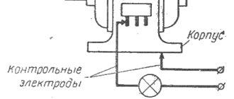
During the operation of level switches with a discrete (relay, transistor) output, an inductive load (devices containing an inductance coil) is often connected. The occurrence of arc discharges when such electrical circuits are opened has an extremely negative effect on the performance of relay contacts and output stages of sensors, reducing their service life.
1.31. Inductive loads and diode protection
ELECTRONICS BASICS
Diodes and diode circuits
Subsections: 1.25 1.26 1.27 1.28 1.29 1.30 1.31
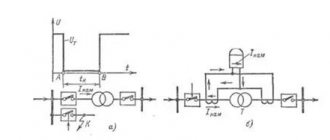
What happens if you open a switch that controls current through an inductance? Inductance, as is known, is characterized by the following property: U = L(dI/dt), and from this it follows that the current cannot be turned off instantly, since in this case an infinite voltage would appear across the inductance. In fact, the voltage across the inductance increases sharply and continues to increase until current flows. Electronic devices that drive inductive loads may not be able to handle this voltage increase, especially components that experience breakdown at certain voltage levels. Consider the diagram presented
Rice. 1.94. Inductive "throw".
in Fig. 1.94. In the initial state, the switch is closed and current flows through the inductance (which can be, for example, a relay winding). When the switch is open, the inductance tends to cause current to flow between points A and B in the same direction as when the switch is closed. This means that the potential of point B becomes more positive than the potential of point A. In our case, the potential difference can reach 1000 V before an electric arc occurs in the switch, which closes the circuit. In this case, the service life of the switch is shortened and impulse noise occurs, which can affect the operation of nearby circuits. If we imagine that a transistor is used as a switch, then the service life of such a switch is not shortened, but simply becomes zero!
To avoid such troubles, it is best to connect a diode to the inductance, as shown in Fig. 1.95. When the switch is closed, the diode is reverse biased (due to the drop in DC voltage across the inductor winding). When the switch opens, the diode opens and the potential of the switch contact becomes higher than the potential of the positive supply voltage by the amount of the voltage drop across the diode. The diode must be selected so that it can withstand an initial current equal to the current flowing in steady state through the inductance; suitable, for example, a diode like 1N4004.
Rice. 1.95. Inductive surge blocking.
The only drawback of the described circuit is that it delays the attenuation of the current flowing through the coil, since the rate of change of this current is proportional to the voltage across the inductance. In cases where the current must decay quickly (for example, high-speed contact printing devices, high-speed relays, etc.), the best result can be obtained if a resistor is connected to the inductor, choosing it so that the value of Ui + IR does not exceed the maximum permissible voltage on the switch. (The fastest decay for a given maximum voltage can be obtained by connecting a Zener diode to the inductor, which provides linear rather than exponential decay.)
Figure 1.96. RC “damper” to suppress inductive surge.
Diode protection cannot be used for AC circuits containing inductors (transformers, AC relays), since the diode will be open during those half-cycles of the signal when the switch is closed. In such cases, it is recommended to use the so-called RC damping chain (Fig. 1.96). The R and C values shown in the diagram are typical for small inductive loads connected to AC power lines. A damper of this type should be provided in all devices operating from AC power line voltages, since the transformer is an inductive load. For protection, you can also use an element such as a metal oxide varistor. It is an inexpensive element similar in appearance to a ceramic capacitor, and in electrical characteristics to a bidirectional Zener diode. It can be used in the voltage range from 10 to 1000 V for currents reaching thousands of amperes (see Section 6.11). Connecting a varistor to the external terminals of the circuit allows not only to prevent inductive interference from nearby devices, but also to suppress large signal spikes that sometimes occur in the power line and pose a serious threat to equipment.
Subsections: 1.25 1.26 1.27 1.28 1.29 1.30 1.31
Other passive components