Electrical faults of the electric motor
Electrical faults in the motor are always related to the winding.
- An interturn short circuit
can occur when the insulation within one winding deteriorates. Possible reasons: winding overheating, poor-quality insulation, insulation wear due to vibration. Determining turn-to-turn short circuits can be difficult. The main diagnostic method is to compare the resistance and operating current of all three windings. The first symptoms of an interturn short circuit are increased heating of the engine and a drop in torque on the shaft. In this case, the current in one of the phases is greater than in the other two. - Short circuits between windings
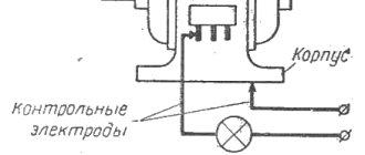
occur due to winding misalignment, mechanical vibration and shock. Without proper electrical protection, a short circuit and fire may occur. - Short circuit of the winding to the housing
. With this malfunction, the electric motor can continue to operate if grounding and short circuit protection are not properly performed. However, in operation it will be deadly, since its potential will be under phase voltage. - Winding break
. This malfunction is equivalent to a phase loss. If a break occurs during operation, the engine suddenly loses power and begins to overheat. If the protection is correctly performed, the motor will turn off because the current in other phases will be increased.
To eliminate most of these breakdowns, a motor rewind is required.
To quickly determine why the electric motor failed and in which components the failure occurred, it is recommended that you familiarize yourself with the list of the most popular faults. Below are typical breakdowns, causes and ways to properly eliminate them.
Malfunction: The electric motor makes a loud noise when starting, does not pick up speed, or does not start at all.
Reason: Open circuit of the stator, open circuit of one of the phases (tip, cable, contactor), burnt out protective insert. Solution: Restore the power circuit, check and replace the fuse.
Cause: Broken stator winding. Solution: Rewind the stator.
Reason: Break in the phase rotor circuit (cable, rheostat, brushes). Solution: Restore the rotor chain.
Cause: Loss of contact between the rods and rings in the squirrel-cage rotor (smoke and sparks). Solution: Rotor repair.
Cause: Jamming of the motor shaft or drive. Solution: Clean the engine or its mechanism from possible contamination.
Cause: Low starting torque, which does not allow the rotor to gain speed. Solution: Replacement with a similar motor with a higher starting torque.
Cause: Star connection instead of triangle Solution: Check the correctness of the connection diagram, reconnect.
Malfunction: Strong heating in the plain bearings.
Cause: Lack or insufficient amount of lubrication. Solution: Lubricate the bearings properly.
Reason: The oil contains impurities and mechanical particles. Solution: Change the lubricant.
Reason: Wear of coupling half parts, ring defect, broken shaft journal, etc. Solution: Repair the mechanical part of the engine.
Fault: Strong heating in the rolling bearings.
Cause: Lack or insufficient supply of lubricant, excess lubricant. Solution: Lubricate the bearings properly, monitor for possible leaks, and remove excess grease.
Cause: Bearing defects, expressed by extraneous noise. Solution: Replace the bearing.
Malfunction: The motor housing becomes very hot during operation.
Reason: Poor performance of the forced cooling system. Solution: Cleaning channels and technological openings.
Cause: Ventilation ducts allowing cold air to pass through are clogged. Solution: Blow with compressed air.
Cause: Increased current load. Solution: Reduce the load or replace it with an electric motor of higher power.
Malfunction: Sparking during ED operation and appearance of smoke.
Cause: The rotor is in contact with the stator surface. Solution: Engine repair.
Cause: Incorrect operation in the protective or ballast system. Solution: Diagnostics of the protective or ballast system and elimination of defects.
Malfunction: Increased vibrations during ED operation.
Cause: Wear of connecting couplings Solution: Disconnect the couplings and check the ED without connecting to the mechanism.
Cause: The alignment of the engine and mechanism is disturbed. Solution: Check and tighten fasteners and frame mounts.
Cause: Bearing wear, rotor imbalance, mutual displacement of the rotor and stator positions. Solution: ED repair.
Malfunction: Fluctuations in the current consumption of the EM stator during its operation.
Cause: Poor connection in the circuit - for a wound rotor, for a squirrel cage rotor - poor connection between the rods and rings. Solution: ED repair (for large fluctuations - immediately, for small fluctuations - the sooner - the better).
Malfunction: Sparks from the commutator-brush assembly. Strong heating and burning of the corresponding fittings.
Cause: Brushes are not sanded well. Solution: Sand the brushes.
Cause: Insufficient clearance for free movement of brushes in brush holders. Solution: Set the permissible gap within 0.2-0.3 mm.
Cause: Contaminated slip rings or brushes. Solution: Clean up and eliminate the source of contamination.
Cause: The slip rings have grooves and irregularities. Solution: Grind and grind the rings.
Reason: Weak brush pressure. Solution: Adjust the pressing force.
Cause: There is no uniform distribution of current between the brushes. Solution: Adjust the pressing force of the brushes and their free movement in the brush holders, check the condition of the Traverse contact group, and assess the condition of the conductors.
Malfunction: The active steel of the stator overheats evenly over the entire surface.
Cause: Increased supply voltage. Solution: Organize additional cooling of the electric motor and reduce the mains voltage to the standard level.
Malfunction: Strong heating of the active steel of the stator in a separate place at idle speed at normal network voltage.
Cause: Local short circuit between individual active steel sheets. Solution: Clean and sand the area where the sheets come into contact, and coat them with dielectric varnish.
Cause: The insulation in the places where the active steel is tied is broken. Solution: Restore insulation in these areas.
Malfunction: The wound-rotor motor does not reach the nominal speed when loading.
Cause: Poor quality connection in the rotor slip ring solder. Solution: Check soldering reliability visually and with a “voltage drop test”.
Cause: Poor contact of the rotor winding with the slip ring. Solution: Check and restore current-carrying connections.
Cause: Weak connection in the brush assembly and the rotor short-circuit mechanism. Solution: Grind and adjust the pressing force of the brushes.
Reason: Weak connection of contact wires in the starting equipment. Solution: Restore the integrity and reliability of contacts in the relevant area.
Malfunction: A motor with a wound rotor starts with an open rotor circuit, and under load cannot reach the nominal mode.
Reason: short circuit in the armature winding, connecting clamps of the frontal connections. Solution: Insulate the contacting clamps, eliminate the short circuit and replace the damaged armature winding.
Reason: Short circuit of the rotor windings in two sections simultaneously. Solution: Eliminate the short circuit and replace the winding of the faulty coil.
Malfunction: The engine with a squirrel-cage rotor does not pick up the normal number of revolutions.
Reason: The thermal relay has worked, the fuses or circuit breaker have failed. Solution: Check and eliminate these faults.
Malfunction: When starting the electric motor, the electric arc covers the slip rings.
Cause: There is dust and dirt in the brush assembly or on the slip rings. Solution: Clean.
Reason: High humidity in the area where the ED is used. Solution: Apply an additional layer of dielectric or replace the ED with another suitable for operation under current conditions.
Cause: Break in the contact connections of the rheostat or rotor. Solution: Carry out diagnostics of all connections and eliminate faults.
Mechanical faults of the electric motor
Mechanical failures of an electric motor are related to its design.
- Wear and friction in bearings
. Manifests itself in increased mechanical vibration and noise during operation. In this case, the bearings must be replaced, otherwise the malfunction will lead to overheating and a decrease in engine performance. - Rotating the rotor on the shaft
. The rotor can rotate in the magnetic field of the stator, and the shaft will be stationary. Mechanical fixation of the rotor to the shaft is required. - Engagement of the rotor with the stator
. This problem is associated with mechanical failure of the bearings, their seats or the motor housing. In addition, such a malfunction leads to damage to the stator winding. Almost beyond repair. - Damage to the motor housing
. May occur due to shocks, increased loads, improper mounting or poor quality of the engine. Repair is labor-intensive due to the difficulty of aligning the front and rear bearings. - Rotation or damage to the blower impeller
. Although the engine will continue to run, it will overheat, which will significantly shorten its service life. The impeller must be secured (using a key or retaining ring) or replaced.
Reasons for failure of electric motors
All faults can be divided into two groups - failure as a result of improper transportation or storage and breakdowns that appeared during operation.
Improper transportation and storage
The main problem that appears during this period is increased humidity, and even more so when the electric machine gets caught in the rain. This leads to a breakdown of the insulation, and in more severe cases, to the appearance of rust inside the device and bearings.
Therefore, before installing such a device, it is necessary to carry out routine repairs and eliminate the detected problems:
- carry out an external inspection of the machine, insulation on the terminals and internal jumpers;
- check the insulation condition with a megger;
- check the presence of lubrication and the condition of the bearings;
- in commutator motors of direct and alternating current, as well as in asynchronous machines with a wound rotor, the condition of the commutator or slip rings and brushes is determined.
All these operations are carried out in a warehouse or workshop near the site of future installation. If it is impossible to eliminate the problems, the electric machine is sent to a specialized enterprise for medium repairs.
Reasons for failure during operation
During operation, the main reasons for failure of an electric machine are:
- Mechanical wear of bearings. This occurs throughout the entire service life, as well as due to increased vibration and irregular lubricant changes. To prevent such situations, it is necessary to carry out full maintenance of all components and mechanisms. Failure to correct the malfunction in a timely manner leads to increased engine vibration, overheating of the bearing shields, wear of the bearing seats and jamming of the rotor.
- Destruction of the housing, bolts and bearing seats. Occurs due to increased vibration of the gearbox and poor alignment of the electric motor. The electric drive must be removed or replaced immediately. The consequences are similar to bearing failure.
- Motor overload and operation of three-phase devices in two phases. Correctly configured thermal relays protect against this. If there is no protection, the device will overheat above the maximum permissible temperature, which will lead to failure of the electric machine.
Reference! New electric motors are equipped with a temperature sensor that turns off the mechanism when the device overheats. It can also be additionally installed in the engine of an older model.
Emergency situations during operation of the electric motor
There are faults that are not directly related to the engine, but affect its operation, performance and service life. Most of these malfunctions are caused by mechanical overload, increased current, and, as a result, overheating of the windings and housing.
- Increased load on the shaft due to jamming of the drive or driven mechanisms.
- Supply voltage imbalance, which can be caused by problems with the power supply or internal problems of the drive.
- Phase loss, which can occur at any part of the motor power supply - from the supply transformer substation to the motor winding.
- Problem with airflow (cooling). It may occur due to damage to the engine impeller due to its own cooling, due to the external forced cooling fan stopping, or due to a significant increase in ambient temperature.
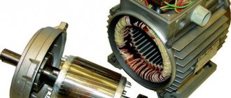
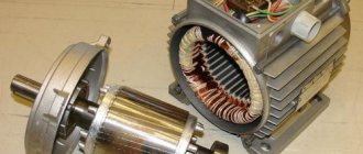
Electric motor design
There is no point in going into details, so we will limit ourselves to a short course. From a design point of view, any electric motor consists of two main parts:
- Stator is a stationary part that is attached to the mechanism body.
- The rotor is the rotating part due to which the devices operate.
In this case, the rotor is located in the stator cavity and does not mechanically contact it in any way, but at the same time it can come into contact through bearings. When analyzing a fan motor or any other device for faults, the first thing to check is the ability of the rotor to rotate. To do this, the first step is to completely remove the voltage from the power circuit and only then can you manually rotate the rotor.
For an electric powertrain to operate, two important conditions are necessary. Firstly, its winding (multiphase electric motors have several of them) must be supplied with a rated voltage. Secondly, both the electrical and magnetic circuits must be in full working order.
Motor protection methods
To protect the electric motor from internal and external faults, as well as to minimize further labor costs for its repair, various devices are used.
Automatic motors and thermal relays
Automatic motors (motor protection circuit breakers) and thermal relays are used to detect excess current in one or all phases of the motor. If it is exceeded, the drive switches off after some time.
Unlike an automatic motor, a thermal relay does not have power switching. It has only a control contact that opens the power supply to the power circuit. The automatic motor is an independent switching device capable of turning off the engine.
The disadvantage of a thermal relay is the lack of short circuit protection. The automatic motor has overload protection and electromagnetic short circuit protection, which instantly triggers and turns off the engine when the set current is exceeded by 10-20 times.
These devices are used most widely and, when properly installed and configured, are highly likely to protect the electric motor and equipment from breakdown and other negative consequences.
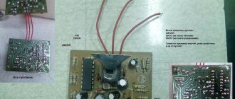
Electronic motor protection relays
This type of protection provides a large selection of different protections. The main element of such relays is a microprocessor that analyzes instantaneous voltage and current values and makes decisions based on the specified settings. This can be a signal to indicate or to turn off the engine.
Thermistors and thermal relays
When for some reason the thermal overload protection does not work, the last line of defense is thermal protection. A temperature-sensitive element (usually a thermistor or posistor) is installed inside the winding, which changes its resistance depending on the temperature. When the threshold is crossed, the corresponding protection is triggered and the engine is switched off.
It is possible to use simpler discrete thermal relays (thermal contacts), which open the control or thermal circuit, which leads to an emergency stop of the electric motor.
Frequency converters
Typically, frequency converters have several types of protection - overtorque and current, overvoltage, phase loss, etc. In addition, torque and current limitation are possible. In this case, the motor will be supplied with voltage at a lower level and frequency if an overload is detected. In this case, a corresponding message will be issued to the operator, and the engine can continue to run.
Manufacturers of frequency converters also recommend installing a circuit breaker at the inverter input, a thermal relay at the output and thermistor protection.
Other useful materials:
Selecting an electric motor for a compressor How to determine motor parameters without a nameplate? Selecting a gear motor for a drilling rig
Uneven stator overheating
In case of uneven overheating, there are several reasons. This could be a breakdown in the stator winding or a short circuit to the housing. Because of this, the teeth not only burn out, but can also melt.
This can also be caused by shorting between some plates caused by burrs. In addition, it cannot be ruled out that the rotor touches the stator housing. In this case, troubleshooting the electric motor will be reduced to cutting out faulty elements and removing burrs. After this, it is necessary to isolate the sheets from each other using mica or special cardboard.
If there is too much damage, the active steel of the stator is re-mixed and all sheets are re-insulated. The stationary part itself is rewound.
Insufficient motor speed
As a rule, identifying mechanical faults in bearings does not answer the question why the electric motor does not gain speed . The cause may be a fault in the driven load. But, if the bearings of an engine free from load are so dirty and worn out that the shaft cannot spin, then this phenomenon will not be observed for very long - due to friction and high heat generation, the steel of the ball bearings will heat up, and they will literally be ground, which will ultimately lead to rotor jamming.
Some of the ball bearing rollers are literally “smeared” across the cage ring
Therefore, the cause of insufficient speed should be sought in internal or external electrical problems. The first step is to make sure the quality of the electricity supplied to the motor terminals - the voltage must correspond to the nominal value.
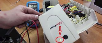
Phase-to-phase voltage is within normal limits
You should also check the contact pads of the starter contactors - at high currents they can burn out, which will cause a voltage drop across them. Faulty, worn contactors may experience contact bounce, resulting in interruption of current.
The oscilloscope screen displays contact bounce that led to a current interruption
A popular way to check the performance of the starter is to connect to it another serviceable electric motor of the same type, the same or slightly less power.
Major faults in the internal electrical system affecting engine speed.
Having ruled out external electrical faults, it is necessary to check the motor windings for breakdown and breakage. The multimeter is switched to megger mode and the insulation resistance of the windings is measured by applying probes alternately to each terminal and the housing. If zero is displayed on the display, then there is an obvious breakdown - somewhere the insulation has frayed and the wire is in direct contact with the housing.
Illustration of the process of measuring the resistance of electric motor windings
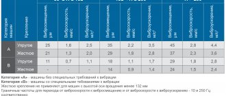
With these measurements, the display may show resistance within a few megaohms - in this case, you need to look at the documentation for the motor and check the insulation resistance graph.
Table for assessing the quality of insulation resistance of electric motors
It is quite possible that high humidity and the presence of small metal shavings in the engine will worsen the dielectric properties of insulating materials. These leakage currents flowing through defective insulation negatively affect both the efficiency of the electric motor and the electrical safety of its operation.
Detection of faults in electric motor windings
A break in one of the windings can cause the engine to not start at all and will hum strongly until the protection is triggered or the remaining coils burn out. To detect a break in the windings of a three-phase asynchronous motor, it is necessary to disconnect the jumpers that form the star or delta connection and check each winding individually.
Illustration of the process of testing electric motor windings
This method will be the most reliable and will not allow a novice master to get confused. The test is carried out in ohmmeter mode. Depending on the quality of the device and the power of the engine, the ohmmeter readings will be close to zero, amounting to several ohms.
It is important here that the resistance of the windings is the same. The condition of equal winding resistance is also true for DC motors. These electric motors have two or more stator windings and multiple rotor windings connected to commutator contact plates.
Continuity check of the rotor windings of a commutator electric motor
If one of the windings has less resistance than the others, this indicates that a short circuit has occurred between some turns of the coil, which is called an interturn short circuit.
Detection of inter-turn short circuit in motor windings
It is precisely this inter-turn short circuit that very often causes the engine to insufficiently rev up. Conventional multimeters are not accurate enough to measure tenths of an ohm. Therefore, additional resistance of the rheostat is used, forming a voltage divider together with the winding under test, a stabilized power supply, a voltmeter and an ammeter. The voltage drop on each winding is measured - if they are in good condition, the voltmeter readings will be the same. A lower voltage will indicate the presence of an interturn short circuit even without calculating the winding resistances, which can be done using the formula shown in the figure.
Calculation of winding resistance via voltage drop
Under the condition of phase equality, an interturn short circuit in the windings of a running three-phase asynchronous motor can be detected by measuring the currents in each phase. An increased current in one phase when connecting the motor windings with a star, or a higher current in two phases when connecting the windings in a triangle, will indicate an interturn short circuit.
Sometimes you can find the place of an interturn short circuit in an asynchronous motor using the traditional method - remove the rotor and apply a reduced three-phase voltage to the windings - no more than 40 V (to ensure electrical safety and so that the coils do not burn out).
A metal ball is placed in the cylinder of a horizontally standing stator, which will begin to roll along the inner surface of the stator, following the rotating magnetic field.
Turn-to-turn fault detection using a steel ball
If the ball suddenly becomes magnetized to one place, then its location will indicate an interturn short circuit.
Basic malfunctions of commutator electric motors
DC and AC commutator electric motors often have a malfunction associated with wear of the contact plates and commutator brushes. With severe wear and contamination of the contacting surfaces, the resistance of the commutator contacts will increase, which will lead to a decrease in torque and engine efficiency.
Cleaning the commutator plates with sandpaper
Ultimately, such wear leads to periodic loss of contact between the brush and the plate, and intermittent operation of the electric motor is observed during rotation.
Damaged rotor commutator contact plates
When starting, such an electric motor may not start at all. If, when voltage is applied, a DC or AC commutator motor sometimes starts after pushing its shaft, then it is necessary to replace the brushes and clean the commutator plates. Sometimes increased sparking is observed at one of the brushes - this indicates a displacement of the brush relative to the central line perpendicular to the axis of the shaft, passing through the center. Centering the brushes will help eliminate this defect.
Correctly align the commutator brushes
You can familiarize yourself with the process of checking brushed motors by watching the video below
Malfunctions in the magnetic circuit, worsening the characteristics of the electric motor
If everything is in order with the mechanical and electrical parts of the AC motor, but it is felt that it is not operating at maximum power and there is increased heat generation, then a short circuit between the magnetic circuit plates is possible.
Alternating current in the magnetic circuit causes eddy currents, which worsen the characteristics of the electric motor, so the stator and rotor are made of laminated plates of special electrical steel. These plates are covered with insulation in the form of an oxide layer, spraying or varnish.
If, due to mechanical damage or rust, the insulation between the laminated plates is broken, a short circuit occurs between them.
Presence of rust on the surface of the rotor magnetic circuit
It is almost impossible to detect a short circuit in the magnetic circuit plates using home measuring instruments, so a full diagnosis of engine faults is needed in a specialized workshop.
Sometimes a short circuit in the magnetic circuit can be detected by careful inspection of the surface, or by noticing local increased heating of the magnetic circuit. But without completely disassembling the entire engine, including the magnetic circuit, this malfunction cannot be eliminated.
The tables below contain the most common malfunctions and breakdowns of electric motors, as well as methods for eliminating them.
Engine fault table, part one
Electric motor fault table, part two