How to make a diagram in Word, create a diagram in Word 2003, 2007, 2010, 2013 or 2021
If you need to supplement the text with graphic elements. For example, tables, graphs, diagrams or diagrams.
That is, this can be done directly in the Word text editor. Without resorting to using third-party programs.
We have already talked about how to make a diagram in Word. This time we will talk about schemes. The Word text editor has many tools for creating diagrams. With their help you can draw various geometric shapes, as well as lines and arrows. In this case, the drawn diagram can be decorated with the help of shadows or other graphic effects.
Drawing electrical diagrams in Microsoft Word
There are a large variety of programs for drawing electrical diagrams. In this article I will tell you how you can quickly draw an electrical circuit diagram using the well-known Word text editor. Here I specifically use the term “drawing electrical circuits” instead of “drawing electrical circuits” because I believe that drawing implies strict execution of the circuit drawing in accordance with GOST, which will not always be convenient in the described method of drawing electrical circuits.
Drawing electrical circuits using Microsoft Word is done using a set of pre-made drawings of electrical and radio elements connected to a document template.
How to make an outline in Word 2007, 2010, 2013 or 2021
So, if you want to make an outline in Word 2007, 2010, 2013 or 2016, then you need to go to the Insert tab. This tab has two buttons that can be used to create diagrams in Word. These are the Shapes and SmartArt buttons.
When you click the Shapes button, a huge list of shapes appears that you can insert into your document.
By selecting one of these shapes from the list, you can immediately draw it in any place convenient for you. Using several of these figures, you can easily make a diagram in Word. An example of a simple circuit in the screenshot below.
If necessary, the appearance of the drawn figures can be changed. To do this, simply select one of the shapes and go to the “Format” tab. On this tab you can change the shape color, frame color, fill color, add shadows and other graphic effects. Using all these features you can create a quite beautiful diagram (example below).
To add text to the diagram, simply right-click on the desired shape and select the “Add text” menu item. Then you can enter text directly inside the shape.
As a result, you can get something like this.
In addition, you can make a diagram in Word using the “SmartArt” button. After clicking on this button, a catalog of ready-made schemes opens. In which you can choose one of the options that suit you.
After selecting the appropriate scheme option, a ready-made scheme will appear on the page.
You will only need to add your text. To do this, just click on one of the blocks and enter the desired text.
You can also change the appearance of the diagram you made. To do this, select the diagram with the mouse and go to the “Design” or “Format” tab. Using the tools available on these tabs, you can get a multi-colored and voluminous diagram like the one in the screenshot below.
How to make a block diagram in word 2010?
If you need to supplement the text with graphic elements. For example, tables, graphs, diagrams or diagrams. That is, this can be done directly in the Word text editor. Without resorting to using third-party programs.
We have already talked about how to make a diagram in Word. This time we will talk about schemes. The Word text editor has many tools for creating diagrams. With their help you can draw various geometric shapes, as well as lines and arrows. In this case, the drawn diagram can be decorated with the help of shadows or other graphic effects.
How to make a diagram in Word 2007, 2010, 2013 or 2016
So, if you want to make an outline in Word 2007, 2010, 2013 or 2016, then you need to go to the Insert tab. This tab has two buttons that can be used to create diagrams in Word. These are the Shapes and SmartArt buttons.
When you click the Shapes button, a huge list of shapes appears that you can insert into your document.
By selecting one of these shapes from the list, you can immediately draw it in any place convenient for you. Using several of these figures, you can easily make a diagram in Word. An example of a simple circuit in the screenshot below.
If necessary, the appearance of the drawn figures can be changed. To do this, simply select one of the shapes and go to the “Format” tab. On this tab you can change the shape color, frame color, fill color, add shadows and other graphic effects. Using all these features you can create a quite beautiful diagram (example below).
To add text to the diagram, simply right-click on the desired shape and select the “Add text” menu item. Then you can enter text directly inside the shape.
As a result, you can get something like this.
In addition, you can make a diagram in Word using the “SmartArt” button. After clicking on this button, a catalog of ready-made schemes opens. In which you can choose one of the options that suit you.
After selecting the appropriate scheme option, a ready-made scheme will appear on the page.
You will only need to add your text. To do this, just click on one of the blocks and enter the desired text.
You can also change the appearance of the diagram you made. To do this, select the diagram with the mouse and go to the “Design” or “Format” tab. Using the tools available on these tabs, you can get a multi-colored and voluminous diagram like the one in the screenshot below.
How to make a diagram in Word 2003
If you are using Word 2003, you can also make an outline and add it to your document. To do this, you must first open the View menu and enable the Drawing toolbar.
,
After this, a toolbar for drawing various shapes will appear in Word 2003. Shapes such as rectangle, circle, line and arrow will be available here.
In order to draw more complex shapes, you can use the “AutoShapes” menu.
Creating a regular diagram
Microsoft's multifunctional editor is an excellent solution for creating and editing text files. It includes various tools to display text easily, such as different fonts, lists, tables or diagrams.
The user's arsenal includes a square, rectangle, circle and its derivatives, as well as others. To use them you need:
To create identical figures, there is no need to constantly use the paste and repeat the above steps again - just copy them in the standard way using the Clrl + C and Ctrl + V keys.
To align elements, they are selected one by one while holding down the Shift . After this, you need to go to the “ Format ” section of the top menu and select “ Align ” in the “ Arrange ” subsection. A list will open where you can align the shapes, for example, along the bottom edge.
How to create a flowchart in Word
To be able to easily connect objects, for example using arrows, you will need to create a flowchart .
To do this, in the “ Insert ” section you need to go to “ Shapes ”, then at the very bottom of the pop-up list click on “ New Canvas ”.
Having moved previously created shapes within its limits, you can connect them using arrows :
The point is that when you further move any of the newly created objects, attached to them will move along with them.
Such tools make it possible not only to create new diagrams, but also to adjust their display if necessary. With each new edition, Microsoft Word expands its arsenal of tools and technologies, and also improves the convenience and ease of use.
When working with text in a Word document, you may come across pictures, diagrams, and drawings. By inserting various objects into the text, it becomes more visual, and those who read it perceive the information better.
In this article we will look at two ways in which you can create a diagram in the MS Word text editor - a SmartArt drawing and inserting regular Shapes. I will show it in Word 2010, but these screenshots are also suitable if you have Word 2007, 2013 or 2021 installed.
The site already has articles: how to add a drawing to Word, and how to make a graph in Word. By following the links, you can read them and make your document interesting and more informative.
How to Draw Diagrams Using SmartArt
A diagram is added to a text editor by inserting a SmartArt drawing into the document. To do this, go to the “Insert” tab and in the “Illustrations” group, click on the “SmartArt” button.
A window like this will appear. In it you need to select a suitable drawing. On the left, click on the section, in the example “Hierarchy”, and select one of the proposed pictures. There's a preview area on the right, see what it looks like and what it's best suited for.
Now let's start placing blocks. You can delete unnecessary ones by selecting it with the mouse and clicking the “Delete” button. Thus, remove all unnecessary rectangles.
Next you need to add blocks. Select the one under which you want to insert additional ones, and on the “Working with SmartArt Drawings” - “Design” tab, click on the “Add Shape” button, in the list click on the “Add Shape Below” item.
After that, select the top rectangle again and add another one below. Here you can choose to add the desired object above, in front of, or behind the selected block.
After you complete the previous step, you need to print the text. Select the diagram area and on the “Working with SmartArt Drawings” - “Design” tab, click on the “Text Area” button. Or, on the left border, click on the button with two small arrows.
A small window will open on the side. In it you need to enter text for each of the blocks. Here markers indicate the levels, and by clicking in front of the marker you can see where the text will be entered.
Write next to each marker which text should be in which object.
When everything is filled out, the window for adding text can be closed by clicking on the cross in it.
Now you can work on the appearance of the circuit itself. To do this, select it and go to the “Working with SmartArt Drawings” – “Design” tab. In the “SmartArt Styles” group, you can choose any other style.
You can also “Change the colors” of the scheme by clicking on the corresponding button.
If the selected view is not very suitable for you, you can change it in the appropriate group. Hover your cursor over any of the proposed layouts to see what your diagram will look like. If this layout suits you better, click on it to select it.
By going to the “Working with SmartArt Drawings” - “Format” tab, you can change any shape or text. For example, select a shape, click “Edit Shape” and click on any other from the proposed list. For each, you can change the fill, outline, or add an effect.
Similarly for text, select it and you can apply one of the ready-made styles, change the fill, outline, or add an effect.
In the end, I came up with this diagram.
How to Draw an Arrow Diagram Using Shapes
You can make diagrams in Word in another way, without using ready-made templates, but create it by inserting suitable shapes into the document.
To do this, open the “Insert” tab, click on the “Shapes” button and click on the one you need from the list, it can be an oval, rectangle, rhombus, etc.
After this, the cursor will change from a stick to a plus sign. Use it to draw a shape at the desired location in the document. Then you will see the “Drawing Tools” – “Format” tab. On it, click on the “Shapes” button again and click on the one you need in the list. Add them all this way.
If you have drawn an object on a sheet and need to move it a little, then you can do this with the mouse, grabbing it by its border. Or select it, hold down the Ctrl key and move it using the arrows on your keyboard.
Next, let's connect the blocks with straight lines or arrows. Select one of them to open the “Drawing Tools” – “Format” tab. Then click “Shapes” and from the drop-down list click, for example, on the arrow. Draw an arrow so that it points directly to the block itself. You can connect several arrows using a straight line.
You can read more about how to make arrows in Word in the article by following the link.
To draw a straight horizontal or vertical line while drawing an arrow, press and hold the Shift key.
Using a straight line and an arrow, I was able to draw this diagram.
Now let's change the appearance of the arrows. Select them one by one, and for each you can choose one of the ready-made styles, or click “Shape Outline” and choose the color, arrow thickness, etc. yourself.
By clicking “Shape Effects” you can add one of the proposed effects. I chose the shadow.
Having drawn and changed the appearance of all the arrows, we move on to the text. Select one rectangle and on the “Drawing Tools” – “Format” tab, click on the “Draw Label” button. A plus sign will appear instead of a cursor. Draw a rectangle with it for the inscription in the desired block.
Next, type the text. Thus, add text to the entire diagram.
As you can see, the rectangle for the inscription is filled with white and has an outline. Let's get this out of the way. Click on it and on the “Drawing Tools” – “Format” tab, select “Shape Fill” – “No Fill”.
We repeat the same for the outline: “Figure outline” – “No outline”. Do this for all text blocks.
The next step is formatting the written text. Select the text and on the “” tab, select the font, size, color and center it.
So, we have changed the appearance of the arrows and the text in the diagram, all that remains is to work with the blocks. Select any of them with the mouse by clicking on it - the “Drawing Tools” – “Format” tab will open. In the “Shape Styles” group, click on the one you like. Or use the Fill, Outline, and Effects buttons to create any look that suits you best.
If, after drawing the diagram, you notice that you need to change one of the blocks, for example, a rectangle to a rhombus, then you do not need to delete it and draw a rhombus, you can simply replace it.
Select a rectangle, for example, go to the “Drawing Tools” – “Format” tab and click on the button that shows a line with markers.
Select “Change Shape” from the list that opens and specify which one to insert.
This is the diagram with arrows that I came up with. You can download everything that was drawn during the writing of this article from Yandex.Disk by following the link:
To move the diagram created in the document a little to the sides or reduce/enlarge it all at once, rather than one shape at a time, you need to group all the drawn objects. Read how to group shapes in Word by following the link.
I will end here. Try to do everything step by step as described in the article, and you will definitely succeed.
Share this article with your friends:
Source: https://word-office.ru/kak-sdelat-blok-shemu-v-word-2010.html
How to make a diagram in Word 2003
If you are using Word 2003, you can also make an outline and add it to your document. To do this, you must first open the View menu and enable the Drawing toolbar.
After this, a toolbar for drawing various shapes will appear in Word 2003. Shapes such as rectangle, circle, line and arrow will be available here.
In order to draw more complex shapes, you can use the “AutoShapes” menu.
how...to draw a flowchart in WORD, EXCEL, POWER POINT, VISIO
Setting up a template for drawing electrical circuits.
In addition, the intersection of the position designation with communication lines, UGO element or any other inscriptions and lines is not allowed.
Users of Microsoft programs are familiar with this interface. However, there is a lot of information, and it is difficult to master it on your own.
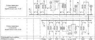
This diagram absolutely accurately and clearly shows the sequence of connecting elements and the type of these elements, which eliminates errors when assembling the device in practice.
The Template drop-down menu allows you to insert ready-made templates of various frames onto the sheet, made in accordance with GOST Figure 3. If necessary, it is possible to change the sequence of assigning serial numbers depending on the placement of elements in the product, the direction of signal flow or the functional sequence of the process. The numbering of elements can be entered automatically or manually, selected in the settings. Now such circuits are practically not supplied with electronic devices, because the seller hopes that it will be easier for the user to throw away the device than to repair it.
EveryCircuit is an online electronics emulator with well-made graphics. Open document dialog box. The cost of the unlimited version is around 3.6 thousand. Reverse insertion of texts and objects created in Word is also performed through a memory buffer.
To get started, you need to download and install not only the program, but also the library with the element base. Here we see: 1. In this section we will collect those products that have received a lot of good reviews.
Description of the toolbar for drawing electrical circuits.
The connection number is assigned automatically, in order from the available figs. The interface of the CAD program is tailored to the familiar appearance of Windows programs, and its size is 15.54 megabytes.
Even with its help, to fully master all the functionality, it will take more than one month of painstaking work, but to develop electrical circuits, you do not need to master the 3D format. After which you can start working. To get started, you need to download and install not only the program, but also the library with the element base. Drawing diagrams in sPlan
Drawing diagrams in sPlan
How to properly make a Flowchart in Microsoft Word
Built-in MS Word software tools provide ample opportunities for constructing and structuring various kinds of Flowcharts. You can, of course, create your own diagram using the various SmartArt shapes and objects. And today we will answer the question of how to make a Flowchart in Word correctly.
When working with shapes in any Microsoft Office application, it is useful to use a grid to ensure that objects are sized and placed correctly. To display its lines, open the “View” tab and check the “Grid” box.
Guide lines will automatically appear in your document. This is one of the main preparatory steps.
Then switch to the Insert tab and select Shapes. The drop-down menu displays an expanded collection of objects from which you can select any one you need.
First, it is important to understand the purpose of the figures. When you hover the cursor over any of them, a hint is displayed. Here's a quick overview of the main ones:
- Process (used for technological operations);
- Decision (used to show decision points);
- Termination sign (indicates the starting and ending points of the process).
Drawing Electrical Diagrams in Microsoft Word - Electronics Basics
There are a large variety of programs for drawing electrical diagrams. In this article I will tell you how you can quickly draw an electrical circuit diagram using the well-known Word text editor.
Here I specifically use the term “ drawing electrical circuits ” instead of “ drawing electrical circuits ” because I believe that drawing implies strict execution of the circuit drawing in accordance with GOST, which will not always be convenient in the described method of drawing electrical circuits.
Drawing electrical circuits using Microsoft Word is done using a set of pre-made drawings of electrical and radio elements connected to a document template.
Setting up a template for drawing electrical circuits
In order to get started, let's make our text editor more convenient for drawing electrical circuits. To do this, install the following template Normal.dot.
We go to the menu File - Open , the dialog box shown in Figure 1 appears in front of us.
Figure 1. Open document dialog box.
Next, we follow the points marked in the figure: 1. In the drop-down list, set the document type to All Word templates . 2. In the Explorer window, indicate the path to the downloaded file Normal.dot . 3.
Select the Normal.dot . 4. Click the Open . Go to the Add-ons in the main menu, where an additional toolbar for the Normal.dot template appears (Figure 2.
)
Description of the toolbar for drawing electrical diagrams
Let's take a closer look at the panel for drawing electrical circuits (Figure 2).
Figure 2. Panel for drawing electrical circuits.
Here we see: 1. Panel for formatting text, paragraphs, inserting special objects and menu for calling utilities.2. A standard toolbar with some additional features.
3. Toolbar Diagram with a set of libraries of electrical radio elements and insertion of standard objects of some shapes.
I think the standard font and paragraph formatting panel won’t create any questions, so I won’t touch on it.
The Scheme drop-down menu completely replicates the Scheme panel , the latter, in turn, is turned on by clicking on the icon in the form of a transistor designation. The Template drop-down menu allows you to insert ready-made templates of various frames, made in accordance with GOST, onto the sheet (Figure 3.).
Figure 3. Menu Templates.
Drop-down menu tools Utilities are designed to print a document in book form.
The Language drop-down menu tools perform various functions related to the document language.
Among the features of the standard toolbar, it is worth noting the presence of buttons: - calling the formula editor; – insertion of symbols;
– display the Scheme .
Scheme toolbar (Figure 4).
Figure 4. Diagram panel.
The panel contains the following blocks: 1. Button for opening the window for snapping objects to the grid.2. A group of tools for formatting an object.3. Group of tools for inserting standard objects.
4. A group of tools for inserting objects from the element library.
The library of tools for drawing electrical circuits consists of sets of basic electrical and radio elements and is presented in Figure 5.
Figure 5. Library of tools for drawing electrical circuits.
Creation of electrical circuit diagrams
For those who know at least a little how to work with Microsoft Word, it will not be at all difficult to create an electrical circuit.
You just need to select the required element in the library, click on it and it will immediately appear in the document.
Now all that remains is to arrange the elements entered in this way as you need on the sheet and connect the connection points of the diagram with lines and the diagram is ready! Don't forget to use standard program tools.
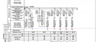
An example of creating a diagram in Microsoft Word can be seen in Figure 6.
Figure 6. An example of creating a diagram in Microsoft Word.
Pros and cons of using Microsoft Word to draw electrical circuit diagrams
Advantages: – no need to install special programs; – ease of creating simple electrical circuits; – free distribution of the described template; - the ability to save the diagram in pdf, html formats.
Flaws:
– the difficulty of creating electrical circuits in accordance with GOST; - when opening a file with a circuit in other versions of Word, document formatting may be disrupted;
– a small set of components for drawing electrical circuits.
Conclusion: this method of drawing electrical circuits is well suited for designing simple circuits. For example, when doing a coursework or dissertation, you need to quickly draw part of a circuit, some kind of cascade or node of a complex circuit. You can also use a text editor to draw electrical diagrams when publishing articles on the Internet.
Watch a detailed video on how to draw electrical diagrams in Microsoft Word:
For those who lack the capabilities of a template for Word, I suggest that you familiarize yourself with templates for drawing electrical circuits in Microsoft Visio.
The set of templates contains a set of conventional graphic symbols made in accordance with Russian GOST and will allow you to draw professional electrical circuits.
DID YOU LIKE THE ARTICLE? SHARE WITH YOUR FRIENDS ON SOCIAL NETWORKS!
Source: https://www.sxemotehnika.ru/programmi-dlya-risovaniya-schem/risovanie-elektricheskich-schem-v-programme-microsoft-word.html
How to Make a Flowchart in Word
Select a shape. Since it will be the first one, we will select "End Sign". Immediately after this, you will notice that the cursor has taken the form of a crosshair. Place it in the desired place in the document and draw the object to the required scale.
The text editor will automatically switch you to the Format tab. It will provide various editing tools for instant application. These are, for example, fill, outline, effects, movement, etc. To insert the required text, simply type it while the form is active.
Next, add “Process” and connect the diagram objects. To do this, use the usual “Arrow”. After selecting it, set the beginning at the lower center adjustment point of the upper block, and the end at the top point of the lower block. The arrow can also be formatted: line thickness, color, etc.
Using SmartArt
There are also several convenient features for creating Flowcharts in SmartArt. Go to the “Insert” tab and click on the desired button. In the selection window, go to the “Process” category on the left, and on the right, click on “Process with offset patterns.”
These graphics are designed specifically for detailed description. It groups shapes to add pictures (photos) and text. Add all required information. You can use other layouts from those available.
If you don't need a specific object, you can delete it. Just highlight and press the delete key. There is also the ability to copy and paste to add additional information. Thank you for your attention!
How to create a flowchart in Word
Summary
To be able to easily connect objects, for example using arrows, you will need to create a flowchart. To do this, in the “Insert” section, you need to go to “Shapes”, and then at the very bottom of the pop-up list, click on “New Canvas”. Having moved previously created shapes within its limits, you can connect them using arrows:
- first you need to add an arrow shape to the canvas using the method described earlier,
- After selecting it, circles will appear in the lower and upper parts. By controlling them, the arrow is attached to the bottom of one element and the top area of another,
The point is that when you further move any of the newly created objects, the pointers attached to them will move along with them.
Such tools make it possible not only to create new diagrams, but also to adjust their display if necessary. With each new edition, Microsoft Word expands its arsenal of tools and technologies, and also improves the convenience and ease of use.
Method 1 Drawing Shapes
Turn on the Drawing toolbar. If you don't see the Drawing panel at the bottom of the window, click the View menu and hover over the Toolbars submenu. Select Draw and the Draw toolbar will appear at the bottom of the window.
Create a starting point. In the Drawing panel, click on AutoShapes. From the menu that appears, select Outlines, and then select the shape you want to start your outline with. A drawing area will appear in your document, inside which will be the inscription “Create your drawing here.”
When the shape size is appropriate, release the mouse button. The starting shapes are usually rounded rectangles or ovals.
If you want to create shapes that are the same shape, turn on the grid by clicking on the Draw button in the Draw panel, then selecting Grid and Margins, and then checking the box called “Display grid on screen.” The grid will allow you to create shapes of precise dimensions.
Create other shapes.
Use different shapes for different concepts in your diagram. Each time a concept of the same type is used, use a figure that represents it. This will improve the readability of your flowchart.
- Process or task blocks are usually rectangular.
- Decision blocks are usually diamond-shaped.
- I/O blocks are usually in the form of parallelograms.
Add text to your shapes.
Right-click on the shape you want to add text to. Click on Add text in the menu that appears. The shape will be highlighted and a text cursor will appear inside it.
You can format text just like any other text in Word.
Adjust the size and position of the shapes.
Once you've added text, you may notice that it doesn't always fit well within the shape. You can resize the shapes by clicking on them and dragging the squares in the corners. Left-click on the center of the shape and hold to drag it around the drawing area.
Method 2 Circuit Connection
- Click the AutoShape button in the Drawing panel.
Hover over Connector Lines and select the style you want to apply. You can choose between straight, broken and curved lines.
Each connecting line can have arrows pointing to either end.
Draw a connecting line.
Place the cursor on the edge of the first shape. Click and drag the connector line to the next shape in order. Word will try to automatically attach the line to the intended point of the second shape.
Once all the shapes are connected, you can move them around the entire drawing area and they will remain connected.
Move a connecting line.
If you use a broken or curved line, you can change the path it takes. Click on a connector to select it. A square will appear in the middle of the line that you can click on and move. This will change the position of the connecting line.
In a similar way, you can move the ends of a connector line by selecting the line, then clicking on the end and dragging it to the location of the new connection.
Add labels to your connecting lines.
In the Picture panel, click the Text Window button. Click and drag your cursor to create a text box anywhere in the drawing area. Place a text box next to any line you want to label.
- Enter your text into the text box, you can format it just like any other text in Word.
- To remove a text window frame, right-click on it and select Format Text Window. In the Borders section, click on the Color drop-down menu and select No Borders.
Description of the toolbar for drawing electrical circuits.
This can be useful for calculating some distances or checking whether a 1.97 meter wide sofa will fit between a 0.8 meter wide wardrobe and a 1.58 meter wide table. A Visio drawing can consist of multiple pages.
And if it’s a football field or a summer cottage, then we play the way we want. Electrical circuit diagram
Features of power supply
And if you want, you can do the opposite, bring an ordinary A4 sheet to dimensions x meters and draw on it some kind of plan of a football stadium or something huge. If you click on this strip, the group that is hidden under it opens.
Programs for drawing electrical circuits
But this will not always work: some shapes are immediately set to the current scale of the document, and then these sizes cannot be changed.
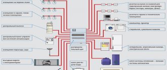
He made me draw a flowchart on a piece of paper. And in order to correctly indicate them on the diagram, it is necessary to study GOST. Here I drew the electrical wiring elements: And here I drew the electrical wiring cable routes without changing the background. For more convenient use in terms of application, a single-line power supply diagram can be of two types: executive; calculated Since they have a chic interface, they have all the functions and electrical symbols. The first type is designed in the presence of existing electrical systems. Everything that doesn’t exist can be programmed.
To create a document on a computer, you need software - a graphic editor that converts the PC user’s manipulations on the information input device into a drawing. It is important to remember that, if necessary, the calculated part of the executive single-line diagram can be increased several times. This option is extremely easy to use even for a non-professional, while being functional and effective at the same time. In these units, Visio will show you all the dimensions. Design of electrical panels. Visio to help + Library.
What is a single line power supply diagram
This is the way Visio sees multiple shapes as one unit and the sizing and rotation squares appear alone on the overall shape.
Here, too, you can create frequently used element designations as templates for using them in further work.
So people made such a drawing so that it would occupy exactly one A4 sheet out of, say, 16. And all this - Visio!
This type of circuit is used for the existing power supply of any room. To do this, you do not need to install any additional programs. Such circuits are needed to correct problems and defects.
Functional - used in cases where there are a large number of different consumers of machines, machines, equipment, and display the overall picture of the network and the interaction between mechanisms, power supplies and with each other. Their number is not particularly limited. Design stages Features of power supply The importance of a linear circuit cannot be overestimated. This simplicity lies in the fact that the entire complex of components necessary to supply consumers with electricity is depicted on it by several lines.
How to make a diagram in Word
When working with text in a Word document, you may come across pictures, diagrams, and drawings. By inserting various objects into the text, it becomes more visual, and those who read it perceive the information better.
In this article we will look at two ways in which you can create a diagram in the MS Word text editor - a SmartArt drawing and inserting regular Shapes. I will show it in Word 2010, but these screenshots are also suitable if you have Word 2007, 2013 or 2021 installed.
The site already has articles: how to add a drawing to Word, and how to make a graph in Word. By following the links, you can read them and make your document interesting and more informative.
How to Draw Diagrams Using SmartArt
A diagram is added to a text editor by inserting a SmartArt drawing into the document. To do this, go to the “Insert” tab and in the “Illustrations” group, click on the “SmartArt” button.
A window like this will appear. In it you need to select a suitable drawing. On the left, click on the section, in the example “Hierarchy”, and select one of the proposed pictures. There's a preview area on the right, see what it looks like and what it's best suited for.
Now let's start placing blocks. You can delete unnecessary ones by selecting it with the mouse and clicking the “Delete” button. Thus, remove all unnecessary rectangles.
Next you need to add blocks. Select the one under which you want to insert additional ones, and on the “Working with SmartArt Drawings” - “Design” tab, click on the “Add Shape” button, in the list click on the “Add Shape Below” item.
After that, select the top rectangle again and add another one below. Here you can choose to add the desired object above, in front of, or behind the selected block.
After you complete the previous step, you need to print the text. Select the diagram area and on the “Working with SmartArt Drawings” - “Design” tab, click on the “Text Area” button. Or, on the left border, click on the button with two small arrows.
A small window will open on the side. In it you need to enter text for each of the blocks. Here markers indicate the levels, and by clicking in front of the marker you can see where the text will be entered.
Write next to each marker which text should be in which object.
When everything is filled out, the window for adding text can be closed by clicking on the cross in it.
Now you can work on the appearance of the circuit itself. To do this, select it and go to the “Working with SmartArt Drawings” – “Design” tab. In the “SmartArt Styles” group, you can choose any other style.
You can also “Change the colors” of the scheme by clicking on the corresponding button.
If the selected view is not very suitable for you, you can change it in the appropriate group. Hover your cursor over any of the proposed layouts to see what your diagram will look like. If this layout suits you better, click on it to select it.
By going to the “Working with SmartArt Drawings” - “Format” tab, you can change any shape or text. For example, select a shape, click “Edit Shape” and click on any other from the proposed list. For each, you can change the fill, outline, or add an effect.