Rational adjustment of the operation of lighting devices in automatic mode can significantly reduce the cost of paying for electrical energy and simplifies the troubles of the home owner.
It's not that difficult to do. It is enough to purchase a modern inexpensive electronic module and understand how to connect a photo relay for street lighting correctly.
In this article I show 11 options for solving this issue. You just have to choose the one that best suits your specific local conditions.
- How the method of mounting the photosensor affects the reliability of the twilight switch
Understanding what electrical processes accompany it helps to properly operate street lighting and troubleshoot problems that arise.
What is a photo relay: a simple and detailed explanation
Additional names for this device are: twilight switch, light sensor, light control switch.
They are created to control artificial light sources depending on the time of day, taking into account the natural illumination of objects by the sun or moon.
During the daytime, electrical sources do not work and turn off automatically. Due to this, energy savings are created without human intervention.
The street lighting of the house turns on only in the dark.
When it is supplemented with motion sensors and timers, the savings result increases many times over.
Photo relays allow you to automatically turn off electrical sources during the day and operate them exclusively at night.
In electrical engineering, the term relay is usually used to describe a technical device that automatically controls one electrical parameter and, when its value passes through a predetermined level, called the “setpoint,” changes its original position and is triggered.
This switches the position of the built-in contacts. They can be closed or open in the initial de-energized position. When the relay is triggered, the contacts abruptly change their state to the opposite - they switch.
The prefix “photo” before the word “relay” means that the device monitors the amount of illumination of the light flux and estimates its value with a built-in sensor.
A semiconductor element of various designs works as a light sensor.
Photosensor: operating principle and how to check it
Light control can be assigned to the semiconductor junction of a photoresistor, photodiode, or phototransistor.
A photoresistor changes its electrical resistance depending on the strength of the light flux hitting it.
In the dark it is about 30 MOhm, and in the light it drops to several kOhm. Its serviceability can be checked with any multimeter if you switch it to ohmmeter mode and cover or remove the light-proof cover in the light.
A photoresistor is used in the most budget photo relay models.
When irradiated with light, a photodiode It is closed in the dark.
On the diagrams it is designated as an LED, but the arrows point to the semiconductor junction, and not to the radiation.
The health of the photodiode is checked with a multimeter, just like a photoresistor. But it is more convenient to use an old pointer tester: the moment of operation will be better visible on it.
A phototransistor can have the same body as a photodiode with two legs, when it is controlled only by the light flux, or with three terminals - for additional operation of its state by the magnitude of the applied electrical voltage.
To facilitate their control, a resistor of a certain size (10-100 kOhm, Mohm) is connected between the base and emitter of three-contact structures. They are also called transistor optocouplers.
Phototransistors are tested in the same way as photodiodes. Only for them it is necessary to take into account the spectrum of light waves. They are more sensitive to it and are tuned to a specific electromagnetic wavelength to operate at a specific color temperature of the source.
When checking with digital multimeters, the forward voltage drop in millivolts is measured at the pn junction. It should be 500-600 millivolts, but depends on the ambient temperature, which takes into account the temperature coefficient of resistance (TCR).
The test is carried out with a dial tester by switching it to ohmmeter mode, and the phototransistor is illuminated with a nearby incandescent lamp.
Photothyristor and photosemistor have a more complex design and are used in special-purpose devices.
Design and diagram of a photo relay for street lighting with explanatory pictures
If we disassemble the body of any photo relay, then inside it we will see mechanical protective and fastening parts designed to ensure reliable operation of the electronic unit.
To connect it to the power supply circuit and lighting fixtures, three wires, usually blue, red and brown, come out of the housing.
The internal circuit of a photo relay for street lighting consists of:
- a photosensor operating on the basis of a photoresistor, photodiode or phototransistor;
- built-in power supply;
- electronic control circuit and photosensor signal amplifier;
- executive body - power relay contacts that switch the load of connected lighting devices.
All this fits on a small electronic board, the design of which differs among different models and manufacturers in the structure, number of parts and components used.
The operating principle of a photo relay is shown in the picture below: the presence or absence of light irradiation from the photo sensor controls the load of the connected light source.
DIY assembly and connection of a photo relay
It’s easy to create a simple device for controlling lighting with your own hands. Depending on the required level of functionality and skills, both simple and complex circuits can be used. In any case, you need to use high-quality parts and provide protection for the element from climatic influences.
Components
For assembly you need to prepare all the necessary parts. A simple version of the photo relay includes components such as:
- photoresistor;
- device Q6004LT;
- regular type resistor.
The connection and connection diagram of the device is simple and includes a minimum of parts. In this case, the device receives power from a 220 V network, and the principle of operation is to gradually increase the voltage amplitude to 40 V. When this mark is reached, the photo relay is activated and the light comes on.
Scheme
Assembling a simple light sensor involves determining the power level and characteristics of the device. First draw up a diagram of connections and connections to the lamp. To use one photo relay for several lamps, you need to use a controller.
Assembly and installation
This circuit does not include a power supply, making the assembly process simple. The power level can be increased by using a device with higher performance. All components are connected using a cable, and a 40 kOhm resistor is used for adjustment.
The use of a powerful Q6004LT device makes it possible to connect a load with a power of up to 500 W to the assembled device. And the use of an additional radiator in the circuit will increase the power to 750 W. In the future, you can use a quadrac, which will have operating currents of 6, 8, 10 or 15 A.
How the connection diagram of a photo relay for street lighting takes into account specific operating conditions
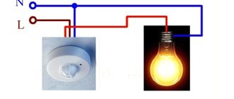
The simplest option for controlling the light of a light bulb using a twilight switch is shown in the picture.
The red wire coming out of the housing is switched to the phase potential of the switchboard. The blue conductor is connected to the neutral and the near contact of the light bulb base.
The third brown wire is the phase potential that the light sensor supplies to the lamp to light it.
This relay connection diagram for street lighting is basic for all cases that are created for different operating conditions. I recommend assembling it on a table and using it when testing a newly purchased twilight switch.
I am showing the assembly of a wiring diagram with an external photosensor, which is output to a separate location using an additional cable.
This technique allows you to effectively evaluate the performance of the device when darkening and illuminating the photosensor, and perform preliminary module settings.
However, it should be taken into account that for modern power supply systems, a protective PE conductor is used for safety reasons. Through it, all housings of household appliances are connected to the building’s grounding loop in the TN-CS, TT systems or the supply transformer substation for the TN-S circuit.
For this situation, all new models of twilight switches have an additional output made with a yellow-green conductor. It is connected to the body of the metal lamp and to the PE bus wiring.
If the luminaire body is made entirely of dielectric materials, then there is no contact for connection to the ground loop. Then there is no need to connect a PE conductor.
The connection diagram for a photo relay for street lighting, taking into account the use of a protective PE conductor, is as follows.
This method is most often used when installing open wiring. If it is made closed with grooves, then the cables are connected inside the junction box.
Pay attention to the switching capacity of the twilight switch output contacts. They must have a power reserve to ensure reliable switching of the controlled load.
If the contacts are weak, then a magnetic starter, contactor or relay with suitable characteristics is simply connected to the circuit. The output power of the switch must be sufficient to control the connected winding.
Then the reinforced contacts of the load repeater will successfully cope with its switching and will not burn out.
Sometimes owners of private houses need to turn on additional artificial lighting at dawn, and not at dusk.
This problem can be solved using the same circuit, only the contacts of the repeater relay should be used not normally closed, but normally open. They will change the operating sequence of the lamp.
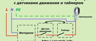
To limit unnecessary electricity consumption at certain periods of time, a timer contact is inserted into the output phase circuit of the lamp. It will ensure that the lighting is turned on for the period required by the owner.
If you connect a motion sensor, the lamp will react to the appearance of a person in the controlled area and illuminate his path. When the visitor leaves the given space, the light turns off.
Similar technical solutions have found application in lighting the entrances of multi-storey buildings.
True, the culture of their performance quite often suffers greatly. Mounting the sensor on electrical tape and the lack of a protective cartridge are not the only shortcomings that characterize the negligent work of housing and communal services electricians.
The greatest effect of saving energy and ensuring a comfortable stay for a person in the operating area of the twilight switch at night is created by the integrated inclusion of a motion sensor and timer.
The motion sensor reacts to the appearance of a person in the twilight switch area and turns on the lamp. The timer, with its contact, turns off the light after a pre-programmed period of time required for the visitor to pass through the controlled area.
Please note: mechanically securing all the components of the connected circuit and connecting them with electrical wires is not a sufficient condition for reliable operation of street lighting.
It is important to position the photosensor correctly and provide it with optimal conditions for error-free operation.
How the method of mounting the photosensor affects the reliability of the twilight switch
Outdoor lamps can be produced separately or in a set with a built-in photosensor, as shown in the picture of installing an LED spotlight.
Here the photosensor is located in the shadow from the direction of the main light of the spotlight. This design may allow false positives.
It is better to place it separately and direct it away from the light source, as done in this photo.
The installation height of the photosensor and its location relative to the lamp should be calculated based on ease of use and operational reliability, but take into account anti-vandal measures.
You can protect the sensor from light from lamps, house windows and other sources with a homemade dark-colored screen.
When installing a photo relay on a powerful lamp, it is placed behind the screen in a shaded area.
When placing the twilight switch on the walls of the house, priority is given to the east or west side. This makes adjustments easier.
Photo relay does not work: what to do
Let's imagine a situation where the new twilight switch together with the lamp is tested under load and voltage after unpacking on the table: there are no comments.
After that, it was installed in the chosen location, and during constant operation, miracles began: it stopped turning on, went out, or worked somehow strangely. Let's look at these cases in more detail.
A working sensor does not turn on the lamp
Let's look at the simplest diagram for connecting a photo relay with a light bulb. The latter will light up if a potential difference between the phase and the working zero is applied to it.
Therefore, it is necessary to check the serviceability of both wires. Usually, novice electricians are limited to checking the phase potential using a simple single-pole voltage indicator in the form of a screwdriver.
You need to use a multimeter: switch it to voltmeter mode and measure the voltage at the input contacts of the lamp.
When it is not there, and the indicator shows the presence of a phase, then you should look for a break in the zero supply chain. This also happens. This happens especially often with old aluminum wires, which simply break in critical places after several bends.
The second reason for the malfunction: the light bulb filament has burned out or broken. We'll have to replace it.
The third case is the settings of the photo relay and motion sensor. Here you will have to correctly determine the viewing angles horizontally and vertically, and also take into account the range of the circuit.
Why does the light not go out when the sensor is working?
The causes of the malfunction may be:
- Movement of people or pets in a controlled area.
- Excessive time delay of the electronic unit to turn off.
- Increased level of brightness control adjustment.
- Formation of residual voltage in the power supply: turn off the device and turn it on again after 20 seconds.
Arbitrary inclusions
The operation of the sensors is influenced by:
- strong electric and magnetic fields from nearby operating electrical equipment. You can protect yourself from them with a continuous grounded shield;
- poor contact of connecting wires;
- increased heating of electronic components;
- gusts of wind affecting the branches of a tree located in the control zone;
- precipitation (snow, hail, rain);
- movement of warm air from air conditioners and fans.
There may be other reasons for external influences. To identify them, you will have to carefully evaluate the specific terrain conditions and the location of the twilight switch.
We draw a conclusion for ourselves: the connection diagram for a photo relay for street lighting requires not only proper installation, but also taking into account local operating conditions.
This concludes the presentation of the material and waits for questions. If you still have them, ask them in the comments.
FR-601 (602)
When it comes to using standard single-phase photo relays for lighting, the most popular model is the FR-601 and FR-602 devices manufactured by IEK.
They are quite reliable, and even users uninitiated in electronics have no questions about how to connect an automatic backlight controller. These two modifications have minor differences: they both operate with current of the same voltage and frequency, have similar power consumption (0.5 W) and absolutely identical delivery kits.
The differences relate only to the maximum cross-section of the connected conductors: for the 601 model it is 1.5 square meters. mm., and for 602 - 2.5. Consequently, their rated load current is also different: 10 and 20 A, respectively. Both models have a built-in photocell; it can be adjusted from 0 to 50 lux in increments of 5 lux.