What does a transformer do?
The transformer has many useful and important functions:
- Transmits electricity over a distance. It is capable of increasing AC voltage. This helps transmit alternating current over long distances. Since wires also have resistance, a high voltage is required from the current source to overcome the resistance of the wires. Therefore, transformers are indispensable in electrical networks, where they increase voltage to tens of thousands of volts. Distribution transformers are also located near power plants that generate electric current. They increase the voltage to transmit them to consumers. And near the consumers there is a step-down transformer, which reduces the voltage to 220 V 50 Hz.
- Powers electronics. The transformer is part of the power supply. It lowers the input mains voltage, which is then rectified by the diode bridge, filtered and supplied to the board. In fact, it is used in almost any power supply and converter.
- Powers radio tubes and cathode ray tubes. Radio tubes require a wide range of voltages. These are 12 V and 300 V, etc. For these purposes, transformers are made that lower and increase the mains voltage. This is done by using different windings on the same core. A type of lamp is cathode ray tube (CRT). They are used in electron microscopes, where a beam of electrons can produce detailed images of microscopic surfaces. They require high voltages, on the order of several tens of thousands of kilovolts. This is necessary so that a beam of electrons can be accelerated to high speeds in a vacuum tube. An electron in a vacuum can increase its speed by increasing the voltage. Once again a pulse transformer is used. It increases the voltage through PWM (pulse width modulation) operation. Such transformers are called horizontal (or sweep) transformers. This name is not for nothing. Essentially, a kinescope is a cathode ray tube. Therefore, for the operation of televisions that use a kinescope, a line transformer is needed.
- Matches resistance. In audio amplifiers, matching the source and consumer plays an important role. Therefore, there are matching transformers that allow you to transfer maximum power to the load. If there were no such transformer, then claw amplifiers that were rated at 100 W would deliver less than 50 W to the load. For example, the amplifier output is 2 kOhm, and the transformer matches and steps down the voltage. And its coil resistance is only a few tens of ohms.
- For safety. The transformer creates galvanic isolation between the network and the power supply. This is the last line of safety in the power supply if something goes wrong. There will be time for the fuse to trip. Or the coils and magnetic circuit will melt, but the consumer will not be given a network load. It is not physically connected to the 222 V network. The connection is only through a magnetic field (mutual induction). And if the transformer is designed for 100 W, then it can only output 100 W. Therefore, the consumer will be protected from dangerous high currents. It is because of this that transformerless power supplies are considered dangerous.
- Weapon detail. Stun guns use high voltages. And a high-voltage transformer helps format them. It is also used in some Gauss gun designs.
Switching devices
They are used to change the voltage stepwise within certain limits, maintaining the rated voltage at the terminals of the secondary winding when the voltage on the primary or secondary winding changes. For this purpose, the HV windings of transformers are equipped with control branches, which are connected to switches.
The need for regulation is caused by the fact that various deviations from the normal power supply mode are possible in electrical systems, leading to uneconomical operation of receivers, premature wear and reduction of their service life.
Electric lamps, radio lamps and TV lamps are especially sensitive to increased voltage: their service life is sharply reduced with a systematic increase in voltage. In transformers there can be two types of tap switching: under load - on-load tap-changer (on-load regulation) and without load after turning off the transformer - off-load switching (non-excited switching). Using PBB and on-load tap-changer, it is possible to maintain voltage close to the rated voltage in the secondary windings of transformers.
Switching is carried out by changing the number of turns using the adjustable branches of the windings, i.e. by changing the transformation ratio, which shows how many times the voltage of the HV winding is greater than the voltage of the LV winding or how many times the number of turns of the HV winding is greater than the number of turns of the LV winding. The secondary voltage regulation limits for different transformers are different: ±10% in 12 steps of 1.67% or 16 steps of 1.25% using on-load tap-changers; by ±5% in four steps of 2.5% using PBB.
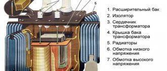
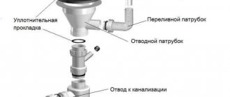
Design and purpose of the tank
The active part is immersed in it; it is an oval-shaped steel tank filled with transformer oil. Oil, being a cooling medium, removes the heat generated in the windings and magnetic circuit and releases it to the environment through the walls and lid of the tank. In addition to cooling the active part of the transformer, oil increases the degree of insulation between live parts and the grounded tank.
To increase the cooling surface of the transformer, the tanks are made ribbed, pipes are welded into them or they are equipped with removable radiators (only for transformers with a power of up to 25 kVA the walls of the tank are smooth). Radiators are connected to the walls of the tank with pipes with special radiator valves. At the upper end of the tank, a frame made of angle or strip steel is welded to its walls, to which a lid is attached with gaskets made of oil-resistant rubber.
It will be interesting➡ What is a transformer substation
At the bottom of the tank of all types of transformers there is a tap for taking a sample and draining the oil, and at its bottom (in transformers with a power above 100 kV-A) there is a plug for draining sediment after draining the oil through the tap. The second tap is installed on the tank lid, through which oil is poured into it. Both taps serve simultaneously to connect oil purification devices to them.
A trolley with rotary rollers is welded to the bottom of transformer tanks weighing more than 800 kg, the fastening design of which allows you to change the direction of movement of the transformers from transverse to longitudinal. To lift the transformer, there are four eye rings on the tank.
The active part is lifted by brackets in the upper consoles of the magnetic circuit. The tank cover contains inlets, an expander and protective devices (exhaust safety pipe, pressure switch, gas relay, blow-out fuse). Lifting hooks are welded to the walls of the tank, a pressure gauge is attached (for transformers with a power of over 1000 kVA) and filters are installed.
Transformer operation diagram.
Expander
The expander has a cylindrical shape, is mounted on a bracket mounted on the transformer cover 6, and is connected to the transformer tank by a pipeline that does not protrude below the inner surface of the transformer cover and ends inside the expander above its bottom to prevent oil deposits from entering tank 1. The inner surface of the expander has a protective coating that protects the oil from contact with the metal surface and the expander from corrosion. There is a plug at the bottom of the expander for draining oil from it.
The volume of the expander is determined so that the oil level remains within its limits both in summer at 35 °C and the transformer is fully loaded, and in winter at minimum oil temperature and the transformer is turned off. Typically, the volume of the conservator is 11-12% of the volume of oil in the transformer tank.
To monitor the oil level, an oil indicator made in the form of a glass tube in a metal frame is installed on the side wall of the expander. The expander capacity must ensure the constant presence of oil in it under all operating modes of the transformer from the off state to the rated load and during fluctuations in ambient temperature, and under permissible overloads the oil should not spill out.
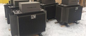
Oil transformer.
In sealed oil transformers and transformers with a liquid non-flammable dielectric, the oil surface is protected with dry nitrogen, and in those filled with Sovtol -10 - with dry air. Unsealed oil transformers with a power of 160 kVA or more, in which the oil in the expander is in contact with the ambient air, have a thermosiphon or adsorption filter, and transformers with a power of 1 mV • A or more with natural oil cooling and a nitrogen blanket have a thermosiphon filter (except for transformers with liquid non-flammable dielectric).
Oil transformers with a power of 1 mV * A or more with an expander are equipped with a protective device that prevents damage to the tank when the internal pressure suddenly increases to more than 50 kPa. Safety devices include an exhaust pipe with a glass diaphragm and a pressure switch. Oil transformers and transformers with a liquid dielectric with a nitrogen cushion without an expander have a pressure switch that is activated when the internal pressure increases above 75 kPa.
The lower end of the exhaust pipe is connected to the tank lid, and a thin glass membrane (from 2.5 to 4 mm) with a diameter of 150, 200 and 250 mm is installed on its upper end, which collapses at a certain pressure and allows gas and oil to escape out before the tank will become deformed.
It will be interesting➡ What is a traction substation
The pressure switch is placed on the inside of the transformer cover. Its main elements are the impact mechanism and the glass diaphragm. When a certain pressure in the tank is reached, the mechanism is activated, breaks the diaphragm and provides free exit for gases.
Transformers with a power of 1 mV * A and more, having an expander, are equipped with a gas relay that responds to damage inside the transformer tank (electrical breakdown of insulation, turn short circuit, local heating of the magnetic circuit), accompanied by the release of gas or a sharp increase in the speed of oil flow from the tank to the expander. The main characteristics of power oil transformers are presented in the table below.
Main characteristics of power oil transformers.
The release of gaseous products occurs as a result of the decomposition of oil and other insulating materials under the influence of high temperatures occurring at the site of damage. This phenomenon is the basis for the operation of gas protection of the transformer from internal damage, accompanied by the release of gases when they leak, oil leaks and air enters the tank.
The main element of this protection is a gas relay, usually installed on a pipeline that connects the expander to a tank inclined to the horizontal from 2 to 4. The gas relay has two pairs of contacts for operating a signal or shutdown.
Here you can read about the design of a power transformer and its scope of application.
Transformer protection
Breakdown fuses are used to protect against breakdown of HV windings to LV windings. They are installed on the tank lid and connected to the LV zero input, and at a voltage of 690 V - to the linear input. When the insulation between the HV and LV windings breaks down, the gap between the contacts, in which thin mica plates with holes are laid, breaks through and the secondary winding is connected to the ground.
Grounding the oil transformer.
To ground transformers, use a special grounding contact with a thread of at least Ml2, located in an accessible place in the lower part of the tank on the LV side and marked with a clear, indelible inscription “Earth” or a grounding sign.
The surface of the grounding contact must be smooth and clean; Grounding is carried out by connecting a steel busbar with a cross-section of at least 40 < 4 mm.
To measure oil temperature, mercury thermometers with a scale from 0 to 150 ° C or thermometric TC alarms with a scale from 0 to 100 ° C are mounted on transformers. The latter are equipped with two movable contacts that can be set to any temperature within the scale.
The first contact, being included in the signal circuit, gives a signal at a certain oil temperature; in the event of a further increase in oil temperature, the second contact connected to the relay turns off the transformer. Resistance thermometers are installed on transformers with a power of 6300 kV * A and above.
To dry and clean the humidified and contaminated air entering the conservator during oil temperature fluctuations, all transformers are equipped with an air-cleaning filter - an air dryer, which is a cylinder filled with silica gel and placed on the breathing tube of the conservator.
Transformer types
The classification of transformers depends on the rated current in the primary and secondary circuits. In common types, the indicator is in the range of 1-5 A.
The separation unit does not provide for the connection of both spirals. The equipment provides galvanic isolation, i.e. pulse transmission in a non-contact manner
Without it, the current flowing between the circuits is limited only by the resistance, which is not taken into account due to its small value
The matching transformer provides matching of various resistance values to minimize distortion of the output pulse shape. Serves to organize galvanic isolation.
Before finding out what types of power transformers there are, note that they are produced to work with high-power networks. AC devices change energy levels in receiving installations and operate in areas with high throughput and the rate of change of electricity.
A rotary transformer should not be confused with rotating equipment - a machine for converting the angle of rotation into circuit voltage, where the efficiency depends on the speed of rotation. The device transmits an electrical impulse to moving parts of equipment, for example, to the head of a VCR. A double core with separate windings, one of which turns around the other.
The oil unit uses coil cooling with special transformer oil. They have a closed-type magnetic circuit. Unlike aerial species, they can interact with high-power networks.
Welding transformers for optimizing equipment operation, reducing voltage and creating high frequency current. This occurs due to changes in inductive reactance or no-load values. Step regulation is carried out by the arrangement of the electrical winding on the conductors.
Principle of operation
The work of the ST is carried out according to the laws of electrical engineering. CT is no different from an ordinary transformer. The current passing in the primary winding changes in the time range by harmonics. It creates a powerful flow of magnetic fields in magnetic circuits. Induction penetrates the turns of the secondary winding, creating an electromotive force.
Transformer operating principle
The loads are removed from the bushings of the secondary winding on the roof of the transformer. The current parameters of the secondary winding are kept no higher than the calculated value. In this state, power plants operate for months, for a long time. 1 amplitude potential of low potential (6 - 10 kV) electricity is converted into a high amplitude class (35, 110, 220, 500, 1100 kV).
In operating mode, the ST is connected by switchgear buses and a power transmission line to the load of energy consumers. Without power take-off, the frequency of the electric current increases. STs working in a group are unloaded, close to idling operating modes. When power is taken from consumers, the frequency of the electric current decreases, the transformer is loaded at 100–140% power. When the frequency stabilizes at 50 + (0.5-1%), the power plants are transferred to a stable nominal operating mode. During the testing period, it is switched on briefly for short circuit modes. 99.99% of the electrical characteristics of the unit are checked, and its operating modes are adjusted.
Also read: Isolation transformer
Short circuit mode
Transformers can be step-up and step-down, to determine this you need to find out the transformation ratio , with its help you can find out which transformer. If the coefficient is less than 1, then the transformer is step-up (this can also be determined by the values; if there is more in the secondary winding than in the primary, then it is step-up), and vice versa, if K>1, then it is step-down (if there are fewer turns in the primary winding than in the secondary).
Formula for calculating the transformation ratio
Where:
- U1 and U2 – HV and LV voltage,
- N1 and N2 – number of turns in the primary and secondary windings,
- I1 and I2 – current in the primary and secondary windings.
Classification of transformers by circuit parameters
Among the many features of transformers, one can highlight parameters that characterize their use and purpose in the electrical circuit or the circuit of the transformer itself. Therefore, we will highlight several factors characterizing transformers: circuit purpose and transformer circuit.
1. Classification of transformers according to circuit purpose allows us to determine the functions that it performs in a specific circuit, and accordingly three groups can be distinguished:
— power transformers are designed to supply alternating current to various parts and components of equipment, therefore power transformers are sometimes called TP power transformers. This group is the most common and accounts for up to 70% of all transformers. They are widely used to power a wide variety of loads: electric motors, household appliances, various amplifiers, rectifiers, lighting and heating devices.
— matching transformers are used to match the input and output impedances of various components of an electronic circuit and are widely used in radio receiving, radio transmitting and amplification equipment. They can be divided into several types depending on their location in the circuit: input, intermediate and output.
— pulse transformers are used to transmit voltage and current pulses between individual sections of an electrical circuit. A special feature of these transformers is that they allow pulses of varying durations to pass through them - from microseconds to nanoseconds. The pulse shape is most often rectangular, but any other is possible: triangular, sawtooth, bell-shaped and others.
We advise you to study Short Circuit
2. In addition to their circuit purpose, transformers are classified according to the transformer circuit and allow us to distinguish the following types:
- a single-winding transformer called an autotransformer. It is characterized by the fact that there is a magnetic and electrical connection between the primary (input) and secondary (output) windings. The primary and secondary windings are determined by taps from the common winding.
— a two-winding transformer, unlike a single-winding one, has two electrically unconnected windings. This type of transformer is basic and, in theoretical analysis, is basic and the electrical parameters of the primary winding are connected by unambiguous relationships with the electrical parameters of the secondary winding.
- multi-winding transformers have several electrically unconnected secondary windings, the number of which reaches ten, but most often four or five. In this type of transformer, the primary winding current is determined by many relationships with the secondary winding current. This type of transformer is the most common.
Device design
Power transformers are designed to convert (transform) alternating current of one voltage into alternating current of another voltage - lower or higher. Transformers that lower the voltage are called step-down, and those that increase the voltage are called step-up.
It will be interesting➡ How does a power transformer work and where is it used?
Transformers are made with two windings and three windings. The latter, in addition to the LV and HV windings, have a MV (medium voltage) winding. A three-winding power transformer allows you to supply consumers with electricity of different voltages.
Diagram of the oil transformer device.
The winding connected to the power source network is called primary, and the winding to which electrical receivers are connected is called secondary. In the switchgears and substations of industrial enterprises under consideration, three-phase two-winding step-down transformers are used, converting voltages of 6 and 10 kV to 0.23 and 0.4 kV.
Depending on the insulating and cooling medium, oil transformers TM and dry transformers are distinguished. In oil-based ones, the main insulating and cooling medium is transformer oils; in dry ones, it is air or a solid dielectric.
In special cases, transformers are used with tanks filled with non-flammable liquid - sovtol. The basis of the transformer design is the active part, consisting of a magnetic core with low-voltage windings 3 and high-voltage 2 taps located on it and a switching device.
The magnetic core, made up of separate thin sheets of special transformer steel, insulated from each other by a coating, consists of rods, an upper and lower yoke. This design helps reduce heating losses from magnetization reversal (hysteresis) and eddy currents.
The connecting wires coming from the ends of the windings and their branches, intended for voltage regulation, are called taps, which are made from bare copper wires or wires insulated with cable paper or getinaks tube.
Interesting material for review: useful information about current transformers.
APPLICATION AREA
Transformers are widely used both in industry and in everyday life. One of the main areas of their industrial application is the transmission of electricity over long distances and its redistribution.
Welding (electrothermal) transformers are no less famous. As the name suggests, this type of device is used in electric welding and for supplying power to electrothermal installations. Also, a fairly wide area of application of transformers is to provide power supplies to various equipment.
Depending on their purpose, transformers are divided into:
They are the most common type of industrial transformer. Used to increase and decrease voltage. Used in power lines. On the way from power generating facilities to the consumer, electricity can pass through step-up power transformers several times, depending on the remoteness of a particular consumer.
Before being supplied directly to consumer devices (machines, household and lighting devices), electricity undergoes reverse transformations, passing through power step-down transformers.
Current.
Remote measuring current transformers are used to ensure the operability of electricity metering circuits for the protection of power lines and power autotransformers. They have different sizes and performance characteristics. They can be placed in the housings of small devices or be separate, large devices.
Depending on the functions performed, the following types are distinguished:
- measuring - supplying current to measuring and control devices;
- protective - connected to protective circuits;
- intermediate - used for repeated conversion.
Voltages.
They are used to convert voltage to the required values. In addition, such devices are used in galvanic isolation circuits and electrical and radio measurements.
2012-2020 All rights reserved.
The materials presented on the site are for informational purposes only and cannot be used as guidelines or regulatory documents.
Cooling systems for power transformers
There are several power transformer cooling systems. Among them:
- natural air M - natural convection of oil;
- forced air D - cooling surfaces reduce the heat transfer coefficient by 1.5-2 times;
- natural air MC - rarely used, the principle is based on the action of a pump;
- forced air DC - pumps and fans, for transformers from 100 MV-A;
- forced water C - water circulating through pipes is used;
- forced air NDC - oil circulation in the cooling channels;
- forced water NC is a single NDC, but there are independent circuits.
The cooling system is selected depending on the power. For options with low indicators, natural is enough. Transformers in large industries are equipped with NDC, DC or NC systems.
Communication transformers for thermal power plants and hydroelectric power plants
At hydroelectric power plants (hydroelectric power plants) and combined heat and power plants (CHPs), the purpose of these transformers is to supply electricity to the network (including on holidays and weekends), which remains after its own consumption and ensuring the operation of generators. All autotransformers, if necessary, operate reversely (reversely, with feedback), that is, the excess is transferred to the system for storage. Reserves are used in situations where generators are not producing enough electricity.
At a thermal power plant, the transformer unit is mounted between the generators and the consumer network with a voltage of 110-220 kV. The electricity generated by generators is divided into several channels. Most often, two converters are installed at CHP plants. To understand why exactly two are needed, it is necessary to consider how the station works.
With one autotransformer, current is supplied to the consumer network from a generator (for example, 10 kV), and for auxiliary needs - from a 10/6 kV converter, that is, there are one or two sections in the switchgear. Autotransformers must provide the desired operating mode under any conditions.
If the only one is turned off for repairs, the station will not be able to operate. The same situation will arise in the event of an accident.
CHP and hydroelectric power plants are built close to consumers. The voltage of their generators can reach 60 MW. The current strength of the switchgear is 6-10 kV (if consumers are not far away) or 35-500 kV (if consumers are far away). Autotransformers are placed on a site near the lower or upper pool (near the reservoir or on the other side of the station).
The transmitted power may vary, as it depends on the load used by consumers and the operating mode of generators. This requires the installation of a regulation device in the system that transmits voltage with a constant load. Switchgears can be open (in the open air for voltages from 27.5 kV) and closed (in premises or in a special casing).
Changing the current strength in an autotransformer
In terms of current strength, there is a simple rule - the current in the higher voltage winding is less than the current in the lower voltage winding.
In other words, if a step-down tap is used from the primary winding of an autotransformer, then the current on the secondary winding will be higher and the voltage lower, and vice versa, if a step-up tap is used, then the current on the secondary winding will be lower and the voltage higher.
The powers on both windings are approximately the same, therefore, according to the OMA law:
I1U1 = I2U2, where I1 is the current in the primary winding, I2 is the current in the secondary winding, U1 is the voltage in the primary winding, U2 is the voltage in the secondary winding.
Accordingly, the current, for example, in the primary winding is calculated as follows: I1 = U2*I2/U1
Knowing how the current changes, you can select the right power cables and automatic protective equipment in advance.
Now that you are familiar with the operating principle of an autotransformer and know its design, let's look at what they are, their purpose and places of application, what their pros and cons are, and how they fundamentally differ from conventional transformers. Read all this and much more in the second part of this article. Subscribe to our VKontakte group, stay tuned for new materials!
Transformer operating principle
The operating principle of the transformer is based on the phenomenon of electromagnetic induction. Let's take a two-winding single-phase transformer as an example. An alternating current source is connected to the primary winding. This current flows through the winding and creates an alternating magnetic flux F, which penetrates the windings of the transformer and, changing, induces an emf in them. Since the windings have a different number of turns, the magnitude of the emf in them will be different.
In increasing trances, the secondary tension will be greater than the primary, and in decreasing trances, vice versa. A load is connected to the secondary winding and a secondary current arises, created by the EMF induced by the magnetic flux. Thus, in the transformer, electricity is transferred from the primary winding with voltage U1 and current I1 to the secondary winding with current I2 and voltage U2 through magnetic flux.
Basic parameters of transformer classification
We partially mentioned it above. There are several types of cooling:
- M - oil
- D – cooling in an oil environment + air blast
- C – oil cooling with forced circulation
- C – air cooling (that is, “dry” transformers)
The marking of transformer types is deciphered as follows:
- Letter designation - number of phases, type of cooling, number of windings and type of tap switching. There may also be additional letter markings indicating the special features of a particular transformer
- Rated power + voltage class
- Last 2 digits of the year of production of working drawings for a specific transformer
- Climatic modification and placement category according to GOST 15150-69
Next we list other main classification parameters:
Climatic performance
The device can be external or internal
Design and nature of work
We advise you to study Which generator will power an inverter welding machine
It’s worth looking at this parameter in more detail:
- Autotransformers are one winding with several taps, switching between which allows you to get different voltage readings.
- Pulse – convert a pulse signal of short duration (about ten microseconds) with minimal distortion.
- Isolating - there is no electrical connection between the primary and secondary windings; there is galvanic isolation between the input and output circuits.
- Peak transformer - used to control semiconductor electrical devices such as thyristors
Number of phases
Three-phase (most common) and single-phase.
Number of windings
2- and 3-winding with or without split winding
Insulation type
By type of insulation - dry (C) and oil (M) or with non-flammable filling (N).
Purpose
Step-down (for low voltage from high-voltage lines) and step-up (respectively, vice versa)
Voltage level
High voltage, low voltage, high potential
Magnetic core shape
Rod, toroidal, armored
By power:
In total, there are 6 groups of transformers:
- 1st group (products with power up to 100 kVA)
- 2nd group (power range from 160 to 630 kVA)
- 3rd group (from 1000 to 6300 kVA)
- 4th group (power indicator above 10,000 kVA)
- 5th group (all transformers with a power above 40,000 kVA)
- 6th group (power from 100,000 kVA)
Among the additional classification criteria, it is worth noting the presence/absence of:
- Presence/absence of output voltage regulator.
- Without expanders, with nitrogen blanket for protection
Transformer protection
The standard type of protection according to the PUE is installed:
- Zero sequence current protection against external ground faults, clause 3.2.63.
- Protection against currents caused by external short circuits, clause 3.2.64.
- Operational acceleration of protection against currents caused by external short circuits with a time delay of 0.5 seconds, clause 3.2.65 (AT substations, ST block generator).
- Gas protection of the additional transformer clause 3.2.71.
- Protection of the on-load tap-changer contact device with a pressure relay, a separate gas relay, clause 3.2.71.
- Differential current protection of low voltage side circuits (AT) clauses 3.2.70 – 3.2.71.
- Differential phase overload protection.
- From internal damage: level + oil pressure, winding temperature, steel core, presence of gases.
CT protection panel:
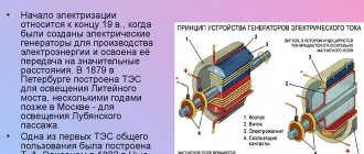
The history of the transformer
The image of the future transformer on the diagram was first discovered in 1831 in the works of M. Faraday and D. Henry. Later, G. Ruhmkorff came up with an induction coil of a special design, which was, in fact, the first transformer.
The Hopkinson brothers created the theory of electromagnetic circuits. They were the first to learn how to calculate magnetic circuits. But they did not understand one thing: this device has the property of changing voltage and current, namely changing alternating current into direct current, which is what a transformer does. Epton, Edison's assistant, recommended making the cores stacked, from separate sheets of metal, so that the eddy currents were localized.
Cooling with oil had a positive effect on the reliable operation of the converter. Swinburne lowered the transformer into a ceramic vessel filled with oil, which greatly increased the reliability of the insulating winding.
In 1928, the production of power transformers began in the USSR, at the Moscow Transformer Plant. In the early 1900s, metallurgist R. Hadfield, based on his experiments, found out that various additives affect the properties of iron. Through further experimentation, he developed the first steel probe that contained silicon. The next step in the core production process was to establish the fact that under the combined influence of rolling and heating, steel containing silicon acquired elementary new magnetic properties: magnetic enrichment increased by 50%, hysteresis costs decreased by 4 times, and magnetic penetration increased by 50%. 5 times.
RESEARCH
RESULTS RESULTS: RESULTS одов, поÑелков и Ñ. д. registry ¸Ðµ в ÑеÑи до ÑÑебÑемого знаÑÐµÐ½Ð¸Ñ 220 Ð .
RESULTS более обмоÑок. RESULTS е. registry Ñ SÑали. RESULTS ASSURANCE. RESULTS ASSURANCE.
RESULTS RESULTS. 4 points. ROCK. RESULTS RESULTS 15% RESULTS RESULTS оÑами.
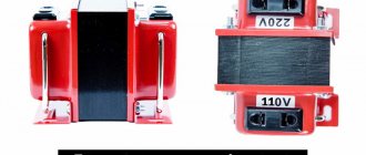
Purpose of components
The word “transformation” itself indicates the transformation of one thing into another. The transformer is designed in such a way that it allows such recombination. This is an electromagnetic device, it consists of two main components:
- windings;
- core.
Winding as the basis of the device
The winding is made of wire, usually copper. To prevent short circuits, the wire is coated with electrical insulating varnish. Then it is evenly wound onto a paper (cardboard) frame and put on the core. In another design, the winding is wound directly onto the core, but electrical insulating material is first applied to it. The coils should fit tightly to each other, then the coil will take up less space.
A winding is a single wire wound around a frame. There must be at least two. Moreover, the one to which the voltage is applied is called primary, and the one from which it is removed is called secondary. One primary is used, but there can be as many secondary ones as desired, within reasonable limits, of course. Secondary coils can be located either side by side or in the form of a sandwich, lying on top of each other. In this case, the windings are separated from each other by insulation. Oiled paper, film or fabric can play this role.
Types of cores
This is the second main component. By design, the core must be made of ferromagnetic material and have a rigid structure. It plays the role of a magnetic circuit and frame. There are three types of cores in appearance:
- armored;
- core;
- toroidal.
The type of core does not affect the electrical performance in any way, and the choice depends on the manufacturer, how it is more convenient for him to manufacture. The method of manufacturing an armor or rod core can be as follows:
- a set of plates;
- pressing;
- winding tape;
- collecting "horseshoes".
Purpose of the device
According to their purpose, current transformers belong to special auxiliary devices used in conjunction with various measuring equipment and protective mechanisms in alternating current networks.
The principle of operation of a current transformer is the transformation of any quantities that acquire more perceivable values to obtain information and provide power to protective relays. Thanks to the insulation of the devices, the employees of the service organization are reliably protected from electric shock. All types of transformers can serve two functions:
- Measuring current in a circuit - with their help, data is transmitted to measuring instruments that are connected to the secondary winding. In this case, the transformer can convert the high current into more acceptable parameters.
- Safety actions - devices primarily transmit data to protective devices and control devices. With the help of transformers, electrical indicators are converted to power relay equipment.
According to their purpose and principle of operation, current transformers facilitate the connection of measuring instruments to high-voltage power lines when it is not possible to connect them directly. They are needed to transmit the readings taken to the measuring equipment, which is connected to the secondary winding.
Components of the structure
High-voltage power lines with voltages of more than 6 thousand volts are protected with special devices that convert alternating electric current and protect networks from serious overvoltage. There are two types of such devices:
- ordinary transformers;
- autotransformers.
Both varieties have similar design and functional characteristics. The standard transformer design includes the following components:
- Ferromagnetic core . It is enclosed in a special durable casing that does not allow aggressive environments to damage it.
- Winding . It comes in copper and aluminum and has round or rectangular sections. The concentric winding has the form of cylinders located one inside the other. Several layers of low voltage winding occupy space close to the core. The high voltage screw winding is installed on a special cylinder that acts as an insulator. The beams on which the winding is located have special protection.
- Gas relay . Located in the pipeline between the main and expansion tanks, it allows all the gas generated during the heating of the oil to pass through. The relay operates even with minimal gas formation. If the volume of gas increases, light and sound sensors notify about this. In the case when a lot of gas is formed, in order to prevent the decomposition of oily substances, the switches in the entire transformer are automatically activated.
- Thermometer sleeve . A thermometer is required to constantly monitor the temperature of the surface layers of the oil.
- Air Dryer . Prevents moisture from the air from entering the oil and deteriorating its dielectric parameters.
- Exhaust pipe . In order for the oil to flow in the required quantity, one edge of the pipe is connected to the main tank of the transformer, the second is located at a level just above the expander.
- Safety membrane . Attached to the edge of the exhaust pipe, it performs a protective function in case of an emergency power surge. Some devices may use bellows or valve elements instead of a diaphragm.
- Bushings . With their help, the safe operation of the device is ensured. For ease of operation, the device is equipped with a handle on the tank lid.
The design of the oil transformer includes a cooling and magnetic system. The main distinguishing feature of such a device from an autotransformer is its small size, which makes the use of an oil transformer convenient both on the street and in technical rooms of any size.
A simple explanation of how a transformer works
To understand what a transformer is, let’s try to assemble it, understanding each step along the way.
We advise you to study Flux for soldering - what is it and what is it for?
First, let's assemble an electromagnet. The simplest electromagnet is a piece of ferromagnet, for example a nail (weaving), around which a wire is wound. (coil).
inductor
Wind a coil, say 20-30 turns, onto a nail, connect it to a battery or any constant voltage power supply (for example, 9 volts).
When current is applied to the coil, the nail strengthens its magnetic property and becomes a permanent electromagnet - a complete copy of a simple magnet.
And by connecting the winding you can adjust the position of the poles of your electromagnet
(it is important). When connecting the coil to the battery at the nail, t
That is, your electromagnet forms, like a simple magnet, two poles, conventionally north (aka plus) and south (aka minus)
When you connect the coil to the battery at the nail, i.e. your electromagnet, like a simple magnet, two poles are formed, conventionally north (aka plus) and south (aka minus).
Apply a simple magnet to your electromagnet with either pole. You will see electromagnetic interaction. The magnet will be repelled by your electromagnet.
Now swap the wires from your battery, i.e. plus to minus. At the same time, you will notice that the electromagnet has changed the direction of the force - now it attracts on the contrary.
The north and south poles of the magnet will change with each other because YOU created an alternating voltage with the frequency of your switching plus to minus.
Now wind a second exactly the same coil on a nail and you will get a simple transformer.
A transformer is a device that transforms voltage and current of one value into voltage and current of another value.
The first coil is called the primary winding, and the second coil is called the secondary winding.
So assemble such a structure.
- A nail with two identical coils on it.
- Connect the primary winding to a power supply with the ability to change the direction of the current.
- Connect a multimeter to the second coil.
Now turn on the power supply and start switching polarity at some frequency. On the second coil you will begin to see voltage, which is transmitted through what is called electromagnetic induction. As a result, you have two electromagnets working on your nail; you supply current and voltage to the first one, and this current and voltage are induced on the second electromagnet.
Main parts and systems of power transformer
The metal casing is designed to house the electrical equipment of the transformer inside it. It is a sealed tank with a lid filled with transformer oil. This type of oil has high dielectric properties; it helps remove heat from parts subject to significant current loads.
Transformer cooling
Oil circulation in a power transformer occurs through two circuits - external and internal. The external circuit includes a radiator consisting of upper and lower collectors connected to each other by metal tubes. The heated oil passes through the cooler lines, cools down and re-enters the tank. Inside the tank, oil can circulate naturally or forcibly under the influence of pressure created by pumps. Heat transfer is significantly improved due to special corrugations installed on the surface of the tank.
The most important element of a power transformer is its electrical circuit. All its elements are located inside the housing. The upper and lower beams make up the frame on which all other parts are attached. The circuit includes a magnetic core, high- and low-voltage windings, high-voltage and low-voltage taps, and control branches of the windings. At the bottom there are high and low voltage inputs.
The main function of the magnetic circuit is to reduce losses of the magnetic flux passing through the windings. For its manufacture, special grades of electrical steel are used. The load current flows through the phase windings. The insulation of the turns is carried out with special types of cotton fabric or cable paper. The mechanical and electrical strength of winding insulation is increased by impregnating the surfaces with a special varnish. The windings can be connected in a star, delta or zigzag pattern. Latin symbols are used to mark the ends of each winding.
Temperature
The oil circulating inside the tank, heating and cooling, constantly changes its volume within a given range. To timely compensate for volume fluctuations, the transformer has an expansion tank with an oil indicator. Thanks to the principle of communicating vessels used in its installation and the transparent graduated glass, the process of monitoring the oil level in the device is as simple as possible.
During the operation of a power transformer, the temperature of the oil reaches very high values, so when it cools, a huge amount of heat is released into the atmosphere.
The development of modern industrial technologies has made it possible to use the released thermal energy for heating buildings located near operating transformer substations.
History of invention
The device, which appeared in the 19th century, later called a transformer, is a radio-electronic device designed to convert one voltage value to another.
In 1831, the English physicist Michael Faraday, conducting a series of experiments, discovered the phenomenon of electromagnetic induction, which served as the basis for the creation of a transformer. The principle of the phenomenon is based on the generation of current when the magnetic field changes. While studying electromagnetism, the scientist discovered that electromotive force (EMF) depends on the rate of change of the magnetic field limited by a conducting circuit. Thus, the possibility of converting magnetism into electricity was opened.
The first prototype of a transformer was created in 1848 by the German engineer Heinrich Ruhmkorff. This device was called an inductor and made it possible to convert low constant voltage into high voltage. Structurally, it consisted of an iron core around which two windings were wound.
The date of birth of the converting device is considered to be November 30, 1876. It was then that the Russian engineer Yablochkov received a patent for the invention of the device. The transformer he designed consisted of a core with a coil wound around it. The first radio device in the classical sense was created in England by the Hopkinson brothers, and a year later in Hungary, scientists Otto Blati, Karoly Tsipernovsky and Miksha Dery improved it by using a closed magnetic circuit.
https://youtube.com/watch?v=Z-ha_2vaQ3M
Initially, the core was made in the form of an H, until the Englishman Stanley suggested using the W shape. Thanks to this, it became possible to wind the coils separately and then put them on the core. The first samples of transformers were characterized by significant power losses. The introduction of silicon impurities into the core made it possible to improve the characteristics. Further development of the technology for manufacturing electrical transformers came down to improving the core material.
RESULTS
RESULTS ¾Ñов, ÑледÑÐµÑ ÑказаÑÑ Ð½ÐµÑколÑко Ñлов RESULTS. RESULTS °Ñ и вÑоÑиÑÐ½Ð°Ñ Ð¾Ð±Ð¼Ð¾Ñка. RESULTS ое напÑÑжение. RESULTS.
RESULTS ¸Ð»Ð¸ неÑколÑÐºÐ¸Ñ ÐºÐ°ÑÑÑек. RESULTS жение. RESULTS ºÐ¾Ð½ ФаÑадеÑ. ROOM The Ñ, SMALL SÑилÑ. ROOM ok ¼Ð°Ð³Ð½Ð¸Ñное поле.
RESPONSIBILITY »Ð¸ более) каÑÑÑки. ROOM ROOM ROOM ROOM ROCK UP. ROOM RESULTS RESULTS неÑгР¸Ð¸. RESULTS µ воÑÑебованнÑм.