All about three-phase transformers: structure, types, principle of operation
A three-phase transformer is a specialized device for changing the voltage in a three-phase alternating current network. The main operating principle of the transformer is based on the effect of electromotive force (EMF) and electromagnetic induction, which eliminates the galvanic connection between the high and low voltage windings.
Three-phase transformers consist of the following main structural parts:
- Magnetic core. Provides a place to fix the windings and creates a direction for the magnetic flux.
- High and low voltage winding. They are windings made of copper or aluminum isolated from each other, which are designed to create a magnetic flux.
- High voltage bushings. Provide safe input/output of high voltage to the corresponding windings.
- Low voltage terminals. Ensure safe connection of power lines to low voltage windings.
- Transformer tank. It is a mandatory element of oil transformers, which creates all the conditions for the operation of the magnetic circuit with windings in transformer oil.
- Switching device (OLTC or PBN). Special devices for changing the parameters of the primary winding in order to maintain a stable voltage value on the secondary winding.
- Control and alarm devices. They provide safe and stable operation of the main electrical equipment, as well as notification of deviations.
The three-phase transformer circuit is selected taking into account the operating parameters of the electrical network, the requirements of electricity consumers and the cost budget.
All three-phase transformers are classified according to numerous criteria:
- Winding connection diagram: star, triangle, zigzag.
- Winding connection group.
- Type of connection of a three-phase transformer to the neutral.
- Main purpose: step-down, step-up, measuring, network protection, intermediate.
- Type of winding insulation: oil, dry insulation,
- Winding material: copper, aluminum.
- Rated voltage: high voltage, low voltage.
- Magnetic core design: rod, armored, armored rod.
Electrotechnical sells a wide range of three-phase transformers from foreign and domestic manufacturers. We provide products that fully comply with all international quality standards.
Source
Transformation of three-phase currents and voltages. Three-phase transformer device.
⇐ PreviousPage 4 of 36Next ⇒
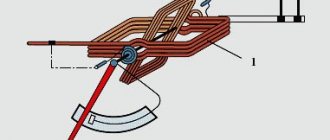
Transformation of three-phase current electricity can be carried out by three single-phase transformers or one three-phase transformer. On each of the three transformer rods there are two windings belonging to the same phase, one of which is primary and the other secondary (Fig. 1). The beginnings of the primary windings are designated by large letters A, B, C, and their ends X, Y, Z; for secondary windings, their beginnings are indicated by small letters a, b, c
, and the ends are
x, y, z.
The physical processes occurring in each phase of a three-phase transformer are no different from those in a single-phase transformer; therefore, the phasor diagram of a single-phase transformer can be considered as the diagram of one phase of a three-phase transformer.
Diagrams and connection groups of three-phase transformers.
The windings of three-phase transformers can be connected in a star or delta configuration. If a star-connected winding has a neutral point brought out, then a zero is added to the star sign. The connection diagram of the transformer windings is indicated in the form of a fraction, the numerator of which indicates the method of connecting the primary winding, and the denominator indicates the secondary winding. For example, “star” / “delta” - the primary winding is connected by a “star” to the neutral terminal, and the secondary winding is connected by a “delta” (Fig. 1, a). The vector diagram of the voltages of the primary and secondary windings is shown in Fig. 1, b.
To conditionally indicate the phase shift angle between the same vectors of linear voltages of the primary and secondary windings, it is customary to divide transformers into winding connection groups
.
Fig.1. Three-phase transformer:
a – connection diagram; b – vector diagram.
To indicate the connection group of a three-phase transformer, the position of the linear voltage vectors of the primary and secondary windings is compared with the position of the clock hands. The linear voltage vector of the primary winding is combined with the minute hand when it is at number 12, and the linear voltage vector of the secondary winding is aligned with the hour hand, the position of which determines the group number (1, 2, 3, ... (12) 0).
Star and delta connection circuits can have 12 different groups with a phase shift of linear voltages of 0֯…330֯ every 30֯. A large variety of connection groups is not convenient for operation, therefore the number of different circuits and connection groups is limited to three: “star”/“star”-0 (the most common connection); "star"/"triangle" -11; “star” with neutral output/ “triangle” -11.
The numbers 0 and 11 indicate a group of transformer connections whose phase shift is 0 and 330֯.
The transformation ratio of a three-phase transformer with a star/star connection is calculated as the ratio of line voltages, and with a star/delta connection as the ratio of phase voltages.
Autotransformer.
Autotransformers are independent devices of the transformer class. Unlike two-winding power transformers, they have one winding for high and low voltages. In this case, the low voltage winding is part of the high voltage winding. Therefore, the windings have not only a magnetic connection, but also a galvanic one; therefore, energy is transferred in two ways: through galvanic coupling and magnetic coupling. A single-phase step-down transformer is shown in Fig. 1.
Fig 1. Diagram of a single-phase step-down transformer.
The high voltage is applied to a winding that has turns, of which the turns are the low voltage winding. With the secondary winding open, the no-load current is set to . The magnetomotive force created by this current induces an emf in the primary and secondary windings of the autotransformer according to the law of electromagnetic induction. Then the transformation ratio
which is equal to the transformation ratio of a conventional transformer. When the load is turned on, a current flows in the secondary circuit, which creates an MMF. Then the magnetic flux in the core
This shows that the current in the common part of the winding is much less, since autotransformers have a transformation ratio of 1
⇐ Previous4Next ⇒
Recommended pages:
Operating principle of a three-phase transformer
Transformers are static electromagnetic devices with the help of which it is possible to convert alternating current from one voltage class to another, with a constant frequency.
In power systems, a transformer that converts electricity to three-phase voltage is called three-phase power.
To transmit electricity from power plant generators to power lines (power lines), step-up transformers are used (they increase the voltage class), from power lines to distribution substations and then to consumers - step-down transformers (they reduce the voltage class).
Design feature
A three-phase transformer has a base - a magnetic core assembled from three ferromagnetic rods.
The rods contain a high voltage primary winding and a low voltage secondary winding. To connect the phases of the primary windings, delta or star circuits are used. The secondary windings are made in a similar way.
Electricity is supplied to the primary winding from the mains, and the load is connected to the secondary winding.
Electricity is transmitted through electromagnetic induction.
The main function of the magnetic circuit is to provide magnetic coupling between the windings. The magnetic core is made of thin steel plates (electrical sheet steel). To reduce losses, steel sheets are insulated between themselves using an oxide film or a special varnish.
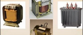
Three-phase power transformer with cast insulation TSL (TSGL) and TSZL (TSZGL)
Three-phase power transformer TS and TSZ
High-voltage discrete transformer-stabilizer VDT-SN
The windings with the magnetic core are immersed in a tank containing transformer oil. It simultaneously performs the function of insulation and cooling medium. Such transformers are called oil transformers. A three-phase transformer that uses air for cooling and insulation is called dry. The disadvantage of oil transformers is the increased fire hazard.
Purpose and design features
In turn, a current transformer is a device that operates on the principle of electromagnetic induction and serves to measure current in high-voltage circuits, as well as to organize protection systems for electrical equipment. That is, in order to measure current in circuits with dangerously high voltages, for example, 6 kV, you cannot simply take a measurement with an ammeter; this is very dangerous both for personnel and for the device itself. Therefore, the main task of current transformers is to separate high-voltage current-carrying parts and convert energy that is safe for both personnel and equipment. Current transformers (CTs) are widely used in relay protection at substations and switchgears. Therefore, high demands are placed on their accuracy and connection. Often, its primary winding is any conductive busbar or cable core; the secondary winding is single or group, with several terminals for protection, control and measurement circuits. Also, metering elements - electricity meters - are connected through current transformers.
That is, according to their purpose, current transformers can be divided into four main groups:
- measuring;
- protective;
- intermediate;
- laboratory
One type of portable device is a clamp meter. They can very easily measure currents in circuits up to 1 kV. True, their measurement range for current is very small; it will be problematic for them to measure loads of 1000 Amps.
Purpose of a three-phase transformer
The main function of transformers is to transmit electricity over long distances. AC electrical energy is generated in power plants. When transmitting electricity, losses occur due to heating of the wires. They can be reduced by reducing the current. To do this, it is necessary to increase the voltage so that its value is in the range from 6 to 500 kV.
The magnification factor depends on the value of the transmitted power and the distance to the final destination.
The power that is transmitted depends on two parameters: voltage and current.
The main characteristic that influences the change in wire losses associated with heating is the current value. In order to reduce heating losses, it is necessary to reduce the current strength. By decreasing the current, the voltage must be increased accordingly. Then the value of the power that is transmitted will remain unchanged.
After the voltage is delivered to consumers, it should be reduced to the required value.
Accordingly, the main task of three-phase transformers is to increase the voltage before transmitting electricity and decrease it after it.
Purpose and structure of a three-phase transformer
Definition 1
A three-phase transformer is a static device that is designed to convert voltage in the process of transmitting electric current over long distances.
The main function of a three-phase transformer is to transmit electrical energy over long distances. AC electrical energy is generated in power plants. During its transmission, losses arise due to heating of the wires. In order to reduce them, the voltage is increased to a value in the range from 6 to 500 kV. The value of the voltage increase depends on the distance to the end consumer and the transmitted power, which consists of two parameters:
Finished works on a similar topic
Course work Three-phase transformer 440 ₽ Abstract Three-phase transformer 220 ₽ Test work Three-phase transformer 190 ₽
Receive completed work or specialist advice on your educational project Find out the cost
- Voltage.
- Current strength.
Among the characteristics that influence losses associated with heating of wires, the main one is current strength. If you reduce the current, then it is necessary to increase the voltage, since in this case the power value will practically not change. When the voltage is delivered to consumers, it is reduced to the required value. Thus, the main task of a three-phase transformer is to increase the voltage before transmitting electrical energy and decrease it after.
The elements that make up a three-phase transformer are divided into main parts and additional equipment. The main parts include: terminals, inputs, magnetic circuit, tank, as well as high and low voltage windings. Additional equipment includes: exhaust pipe, blow-out fuse, expansion tank, control and alarm devices, exhaust pipe, insulators, filler hole, cooling pipes, etc.
The magnetic core is designed for fastening all components. Its second function is to create the direction of movement of the main magnetic flux. Depending on how the windings are attached to the core, the magnetic circuit can be of three types: rod, armored and armored rod. A very important element of a three-phase transformer is oil, which is used in medium and high power devices. Its main functions are increasing insulation and cooling the windings. An example of a transformer circuit is shown in the figure below.
Are you an expert in this subject area? We invite you to become the author of the Directory Working Conditions
Figure 1. Transformer diagram. Author24 - online exchange of student work
1 - magnetic circuit; 2.3 - high and low voltage windings; 4 — tank with transformer oil; 5,6 - insulators; 7 - switch; 8 - cooling pipes; 9 — expansion tank; 10 — oil level meter; 11 - filler hole.
Definition and types of device
A three-phase transformer is a static device with three pairs of windings. The device is designed to convert voltage when transmitting power over long distances.
Classification by number of phases:
- single-phase;
- three-phase.
Single-phase transformers have low power. The main areas of their application are everyday life and special-purpose work (welding, measurements, testing).
The power range of three-phase transformers varies widely. Therefore, their scope of application is very diverse:
- for powering special-purpose current collectors;
- for connecting measuring instruments;
- to change the voltage value during testing;
- to increase or decrease voltage when connecting lighting or power load.
Operating principle
The basis of a three-phase transformer is a magnetic core and windings. Each phase has its own step-up and step-down winding. Since there are three phases, there are six windings. They are not connected to each other.
The operating principle of a three-phase transformer, like a single-phase one, is based on the law of electromagnetic induction.
When the primary winding is connected to the network, alternating current begins to flow in it. Because of it, a main magnetic flux appears in the steel core of the magnetic circuit, which covers the windings in each phase. In each turn, an electromotive force of the same value and magnitude appears.
If the number of turns of the secondary winding is less than the number of turns of the primary, then the output voltage will be lower than the input and vice versa.
The fact that the value of the electromotive force depends only on the number of turns of a particular winding is confirmed by the formulas:
E 1 = 4, 44f 1 Ф W 1
E 2 = 4.44 f 1 Ф W 2
E 1, E 2 - the value of the electromotive force in the primary and secondary windings, respectively, V;
f 1 - frequency of current in the network, Hz;
Ф — maximum value of the main magnetic flux, Wb;
W 1, W 2 - the number of turns in the primary and secondary windings, respectively.
Transformation of three-phase current and connection diagrams of windings of three-phase transformers
2015-03-22 10920
Rice. 1.20. Transformer group (a) and three-phase transformer (b)
Transformation of a three-phase voltage system can be carried out by three single-phase transformers connected into a transformer group (Fig. 1.20, a). However, relative bulkiness, heavy weight and increased cost are a disadvantage of the transformer group, so it is used only in high-power installations in order to reduce the weight and dimensions of the unit of equipment, which is important when installing and transporting transformers.
Rice. 1.21. Three-rod magnetic circuit and vector diagrams
In installations with a power of up to approximately 60,000 kVA, three-phase transformers are usually used (Fig. 1.20, b), in which the windings are located on three rods, combined into a common magnetic circuit by two yokes (see Fig. 1.2). But the magnetic circuit obtained in this way is asymmetrical:
the magnetic resistance to the flow of the middle phase
PV
is less than the magnetic resistance to the flows of the extreme phases
FA
and Fs (Fig. 1.21, a).
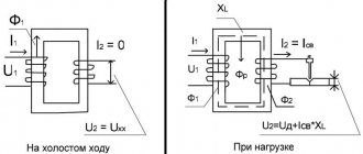
Since a symmetrical voltage system is supplied to the primary windings of a three-phase transformer
and then magnetic fluxes and appear in the magnetic circuit of the transformer, forming also a symmetrical system (Fig. 1.21,
6).
However, due to the magnetic asymmetry of the magnetic core, the magnetizing currents of the individual phase windings are not equal: the magnetizing currents of the windings of the outer phases ( and ) are greater than the magnetizing current of the middle phase winding
.
In addition, the currents turn out to be shifted in phase relative to the corresponding flows and by an angle α. Thus, with a symmetrical three-phase voltage system supplied to the transformer, the currents x.x. form an asymmetrical system (Fig. 1.21, c).
To reduce the magnetic asymmetry of the three-rod magnetic circuit, i.e.
to reduce the magnetic resistance to the flows of the extreme phases, the cross-section of the yokes is made 10-15% larger than the cross-section of the rods, which reduces their magnetic resistance. The asymmetry of the currents of a three-rod transformer practically does not affect the operation of the transformer, since even with a small load the difference in the values of the currents becomes
unnoticeable.
Thus, with a symmetrical supply voltage and a uniform three-phase load, all phases of a three-phase transformer made on a three-rod magnetic core are practically in the same conditions. Therefore, the voltage, MMF and current equations discussed above, as well as the equivalent circuit and vector diagrams can be used to study the operation of each phase of a three-phase transformer.
The windings of three-phase transformers are usually connected according to the following circuits: star; star with zero terminal; triangle; zigzag with zero output. The connection diagrams of the transformer windings are designated by a fraction, the numerator of which indicates the connection diagram of the HV windings, and the denominator - the LV windings. For example, Y/A means that the HV windings are connected in star and the LV windings are connected in delta.
Rice. 1.22. Connecting windings in a zigzag
Zigzag connections are used only in transformers for special purposes, for example in transformers for rectifiers (see § 5.2). To make the connection, each phase of the LV winding is divided into two parts, placing them on different rods. The indicated parts of the windings are connected so that the end of one part of the phase winding is connected to the end of another part of the same winding, located on another rod (Fig. 1.22, a).
A zigzag is called
equal-armed
if the parts of the windings located on different rods and connected in series are the same, and
unequal-armed
if these parts are unequal.
When connected in a zigzag, the EMF of individual parts of the windings is geometrically subtracted (Fig. 1.22, b).
The terminals of transformer windings are usually designated as follows: HV windings - the beginning of windings A, B, C,
corresponding ends
X, Y,
Z;
LV windings - the beginnings of windings a, b, c,
the corresponding ends
x, y, z.
When the windings are connected by a star, the linear voltage is greater than the phase voltage (), and when the windings are connected by a triangle, the linear voltage is equal to the phase voltage (Ul = Uph).
The line voltage ratio of a three-phase transformer is determined as follows:
| Winding connection diagram | Y/Y | ∆/Y | ∆/∆ | Y/∆ |
| Line voltage ratio |
Thus, the ratio of line voltages in a three-phase transformer is determined not only by the ratio of the number of turns of the phase windings, but also by the diagram of their connections.
Example 1.3. Three-phase transformer with rated power Snom =
100 kVA is connected according to the Y/∆ circuit.
In this case, the rated line voltages at the input and output of the transformer are respectively equal: U1nom
= 3.0 kV,
U2nom
= 0.4 kV.
Determine the ratio of turns wllw2
and the rated values of phase currents in the primary I1ph and secondary I2ph windings.
Winding connection diagrams and groups
In three-phase transformers, it is necessary to connect the primary windings in phases and the secondary windings.
There are three connection schemes:
- star;
- triangle;
- zigzag.
When connecting the windings with a star, the linear voltage - between the beginnings of the phases - will be 1.73 times greater than the phase voltage (between the beginning and end of the phase). When connecting the transformer windings with a triangle, the phase and line voltages will be the same.
It is more advantageous to connect the windings with a star at high voltages, and with a triangle at high currents. Connecting the windings in a zigzag makes it possible to smooth out the asymmetry of the magnetizing currents. But the disadvantage of this connection method is the increased waste of winding material.
To main§ 84. Three-phase transformers
Three-phase transformers are manufactured mainly as rod ones. The diagram for obtaining a three-phase core transformer is shown in Fig. 105. Three identical single-phase transformers are made so that their primary and secondary windings are placed on one core rod, and the other magnetic core rod of each transformer does not have a winding (Fig. 105, a). If these three transformers are arranged so that the rods that do not have windings are located next to each other, then these three rods can be combined into one - O
(Fig. 105, b).
Through the combined rod O
, the magnetic fluxes of three single-phase transformers will be closed, which are equal in magnitude and shifted in phase by one third of the period.
Since the sum of three magnetic fluxes equal in amplitude and shifted in phase by 1/3 of a period is zero at any time (Φ a
+ Φ
b
+ Φ
c
= 0), then there is no magnetic flux in the combined rod and there is no need for this rod . Thus, for a magnetic circuit it is enough to have three rods, which, for design reasons, are located in the same plane, as shown in Fig. 105, v.
Each core of a three-phase transformer houses the high and low voltage windings of one phase. The rods are connected to each other by a yoke at the top and bottom. It is easy to see that the length of the magnetic flux lines of the middle rod is less than that of the outer rods, so that the magnetic flux of the middle rod encounters less magnetic resistance along its path than the magnetic fluxes of the outer rods. Therefore, in the phase whose winding is placed on the middle rod, less magnetizing current flows than in the phases whose windings are placed on the outer rods. Structurally, the windings of three-phase transformers are made in the same way as the windings of single-phase ones. The beginnings of the phases of the high voltage windings are designated by the letters A, B
and
C
;
of
the high voltage windings - X, Y
and
Z. If the high-voltage winding has an exposed zero point, then this terminal is designated by the
letter
O. The terminals of the low voltage windings are designated by letters: a, b, c
- the beginning of the phases and
x, y, z
- the ends of the phases;
0
—zero point output. The windings of three-phase transformers can be connected in star and delta. When connecting the windings with a star, the ends (or beginnings) of all three phases are connected to each other, forming a common neutral or zero point, and the free terminals of the beginnings (or ends) of the three phases are connected to the three wires of the source (or receiver) network of alternating current electrical energy. When the windings are connected in a triangle, the beginning of the first phase is connected to the end of the second, the beginning of the second phase is connected to the end of the third, and the beginning of the third phase is connected to the end of the first. The connection points between the beginning of one phase and the end of another are connected to the wires of a three-phase alternating current network. The connection of the windings of three-phase transformers is denoted by a star as Y, and by a triangle as Δ. If the windings are connected by a star and have a derived zero point, then such a connection is indicated. Groups of three-phase transformers are indicated by signs of the following form:
where the sign above the line shows the connection diagram of the higher voltage windings, the sign below the line shows the connection diagram of the low voltage windings, the number is the angle between the linear voltage vectors of the high and low voltage windings, expressed in the number of angular units of 30° each. Thus, the first designation of the group shows that the windings of higher and lower voltage are connected by a star, and the lower voltage windings have a derived zero point, and the angle between the vectors of linear e. d.s. windings of high and low voltage is 12 · 30° = 360° or 0°. Groups of three-phase transformers depend on the winding connection diagrams, the designation of the phase terminals of the high and low voltage windings, and the direction of the windings. If the direction of winding of the turns of the high and low voltage windings is the same, then e.g. d.s., induced in the phases of the high and low voltage windings, coincide in phase; if the windings have the opposite winding direction, then e.g. d.s. the phases of the highest and lowest voltage are in antiphase. In the USSR, the standard groups are the following:
As you can see, in standard groups, the higher voltage windings are connected in a star, since with such a circuit the phase voltage is several times less than the linear voltage, as a result of which the insulation of the windings is simplified. Low voltage windings are often connected in a triangle, on the basis that with this connection the transformer is less sensitive to phase load asymmetry. The low voltage windings are also connected according to the “star-zero” circuit, which makes it possible to use a four-wire network and obtain two different voltages in it - linear and phase (for example, 127 and 220 V
, 220 and 380
V
, etc.).
Previous page
| table of contents | Next page |
A little bit of history
The invention of transformers began back in 1876 by the great Russian scientist P.N. Yablokov. His product did not have a closed core; it appeared later - in 1884. And with the advent of the device, scientists became actively interested in alternating current.
For example, already in 1889 M.O. Dolivo-Dobrovolsky (Russian electrical engineer) proposed a three-phase alternating current system. He built the first three-phase asynchronous motor and transformer. Two years later, a presentation was made of a three-phase high-voltage line with a length of 175 km, where electricity was successfully increased and decreased.
A little later, oil units appeared, since oil not only turned out to be a good insulator, but also an excellent cooling medium.
Source
Three-phase power transformer
A three-phase transformer is a static device with three pairs of windings, designed to convert voltage when transmitting electric current over long distances. This conversion can be accomplished using three single-phase transformers. But the complex apparatus has significant dimensions and weight. A three-phase transformer is free from these disadvantages, due to the fact that the three windings are located on a common magnetic core. Three-phase devices are successfully used in networks with a power of up to 60 kVA.
Purpose of a three-phase transformer
The main task of such a device is to transform the parameters of the electric current in such a way that losses when heating the wires are minimal. To solve this problem, it is necessary to reduce the current and increase the voltage value to 6-500 kV so that the power value remains constant. After delivering electric current to the consumer, the voltage must be reduced to the required value - 380 V. And this problem is also solved by three-phase devices.
These devices are also used for connecting measuring instruments, changing voltage when conducting tests or connecting a power load.
Operating principle and design of a three-phase power transformer
The design of this device includes:
- Magnetic core. All parts of the device are attached to it. It also serves to create the main magnetic flux. The magnetic core can be rod, armored rod, or armored.
- Windings In each phase there are two windings - step-down and step-up. The windings can be connected “star” or “delta”. In the first case, the linear voltage (between the beginnings of the phases) is 1.73 times higher than the phase voltage (between the beginning and end of the phase). When connected by a delta, the line and phase voltages are the same. A star connection is effective at high voltages, a delta connection at high currents.
- Inputs and conclusions. Necessary for connecting the ends of windings to power lines. The input is connected to the primary winding, the output to the secondary.