Digital
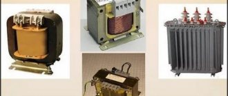
Today, measurements are more often carried out with a digital wattmeter. They can measure both active and reactive power. The devices are equipped with a display that displays not only power, but also other characteristics of the wattmeter - current, voltage or, for example, electricity consumption for a certain time period. If modern digital models are used, they allow you to display all the results obtained on a remote PC.
Principle of operation
When a wattmeter is connected to a circuit, the measurement occurs indirectly using Ohm's law. An assessment is made of the drop in current readings on the shunt, as well as the voltage drop, after which the resulting values are processed by a microprocessor and, based on them, the power is calculated, and the total electricity consumed by the consumer is determined. After all measurements have been taken, the data is displayed.
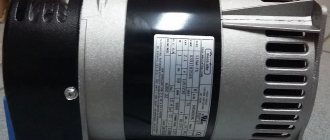
Household devices
This type of device usually refers to digital devices; they are produced in the form of a network adapter. Needed to measure the power of the device used or to determine the cost of electricity, if it is possible to independently set the cost of a kilowatt-hour. The principle of their operation is quite simple: a wattmeter is inserted into a socket, and in turn, the device under study is plugged into the wattmeter socket.
When you press the corresponding button, the countdown of the amount of energy consumed begins and its cost is immediately determined. If you need to determine the amount of power consumed, you simply switch the button, you can also determine current, voltage, or any other parameter, their number depends on the functionality of the model.
The measurement limit of this type of wattmeter usually does not exceed 4 kW. That is, by connecting almost any household appliance, you can easily determine the monetary costs that you will have to pay for its operation, for example, for a month.
Operating principle of an analog wattmeter
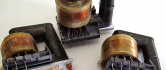
The basis of the design of the most common analog wattmeters is the electrodynamic system. Devices of this type make it possible to make the most accurate measurements and obtain the necessary results.
The operating principle of an analog-type wattmeter is based on two interacting coils. The first coil is stationary; its design uses a thick winding wire with a small number of turns and low resistance. This coil is connected in series with the consumer.
The second coil is in motion. A thin conductor with a large number of turns and high resistance is used for its winding. This coil is connected in parallel with the consumer and is equipped with additional resistance to protect against winding short circuits.
When the wattmeter is connected to the network, magnetic fields appear in the windings of its coils, interacting with each other. Due to this interaction, a torque is generated that deflects the moving winding by the calculated angle. This indicator is influenced by the product of current and voltage at a specified point in time.
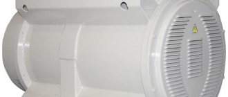
Professional
These are more functional devices, they belong to stationary equipment, and are larger in size than their household counterparts. The error of a wattmeter for professional use is minimal; they operate within a wider range of current, voltage, and frequency.
Naturally, such devices are more expensive than their household counterparts; they are subject to higher requirements in terms of accuracy class, functionality, and other characteristics. They work with any current and can determine power with a wattmeter in single-phase and three-phase networks.
There are also panel wattmeters; they are built into single-phase or three-phase networks. They are highly accurate, the results are transmitted in the form of numbers to the display. The appearance of the device resembles a measuring head, which is mounted in the housing. Most often used in instrument panels.
Wattmeters are chosen depending on the area of application and purpose; there is no need to overpay for a functional device if you need to measure the power of a home refrigerator, but a household device is not suitable for professional use.
Wattmeter
Details Category:
WATTMETER
, a device for measuring electrical power consumed in some part of an electrical circuit. In technology and in laboratory practice, two types of wattmeter are used: electrodynamic and induction.
An electrodynamic wattmeter is based on the interaction of currents and consists of two windings (Fig. 1): stationary and
, carrying the entire circuit current I, and mobile b, carrying current i, proportional to the circuit voltage. The moving winding is connected in series with a large non-inductive resistance and is connected in parallel to the receiver. Current is supplied to the moving winding through two spiral springs c, which at the same time create a torque that counteracts the rotation of the winding.
For sinusoidal currents, if E is the effective voltage, I is the effective current of a single-phase circuit and ϕ is the phase angle between current and voltage, the power P consumed in the circuit is expressed by the product:
In electrodynamic wattmeters, the interaction of two magnetic fluxes F1 and F2, created by the currents I and i in the windings, forms a torque:
Here α is the lag angle of the current i in the moving winding of the wattmeter, which has an inductance L. Due to the presence of the angle α, the moment M is not entirely proportional to the power P; Therefore, the calculation of the device must be carried out so that the error of the wattmeter created by the angle α does not exceed the limits of the reading accuracy. Because
then the angle α can be reduced by introducing a large additional resistance into the moving winding circuit. This resistance is made of a material with a negligible temperature coefficient and makes the device insensitive to changes in ambient temperature. From the transformation of formula (2)
it follows that this same additional resistance makes the device insensitive to changes in the frequency of the current, since at a small value of the fraction it can be assumed that the Electrodynamic wattmeter is a precision instrument and is used in Chap. arr. in laboratory practice. Its advantages: high accuracy (up to 0.25%), suitability for direct and alternating current, independence of readings from current frequency, voltage curve shape and temperature. Disadvantages: lightweight design, weak magnetic fields, low torque and, as a result, a strong influence of the external field on the wattmeter readings. To reduce this influence and adapt the electrodynamic wattmeter to the operating conditions on switchboards, use an iron casing that protects the wattmeter mechanism from the action of an external field, or arrange the entire magnetic circuit of iron, thus enhancing the field and torque.
The mechanism of an electrodynamic wattmeter is shown in Fig. 2.
An induction wattmeter differs from an electrodynamic one in that the current into the moving system is not supplied from the outside, but is induced by currents in the stationary windings (Fig. 3).
An induction wattmeter consists of a ring-shaped core a
with two pairs of inwardly projecting poles b, enclosing a central cylindrical core c; both cores are made of sheet iron. In the gap between the poles and the cylinder, a thin-walled aluminum drum d rotates on supports. A winding is located on each pole of the ring-shaped core; windings of diametrically opposite poles are connected in series. One pair of windings carries the entire current of the circuit, the other carries a current proportional to the voltage of the circuit, and in this winding a 90° lag between the current and the voltage is artificially created. When such a wattmeter is connected to an alternating current circuit, the pulsation of two fields, shifted by 1/4 of a period in time and 90° in space, creates a rotating field that induces a current in the drum and causes it to rotate. The counteracting moment is developed by spiral or cylindrical springs. The torque of an induction wattmeter is expressed by the formula:
where c is the frequency of the current and ϱ is the resistivity of the drum material. An induction wattmeter cannot be used. classified as precision instruments, since its readings depend on the shape of the voltage curve, on the frequency of the current and on the temperature of the medium. An induction wattmeter is only suitable for alternating current and is calibrated to a specific frequency. Its advantages: durable and strong design, weak influence of external fields.
Therefore, an induction wattmeter is an excellent technical device and is successfully used on distribution boards. The mechanism of an induction wattmeter is shown in Fig. 4.
Typically, wattmeters are made for moderate currents and voltages: 100-200 A, 120 V. For voltages up to 600 V, external additional resistances are used in the voltage circuit.
For currents greater than 200 A and voltages above 600 V, five-amp wattmeters of 100-120 V are used in connection with current and voltage transformers. To measure the power of three-phase current, there are various special wattmeter designs: 1) single-phase wattmeter, connected to line current and phase voltage; the wattmeter measures phase power, but is calibrated to the power P of three-phase current: it is only suitable for a uniform load; 2) a single-phase wattmeter connected to line current and line voltage according to the diagram in Fig. 5; a choke is connected to the voltage circuit, giving an additional phase shift of the current in the voltage winding by 30°; the wattmeter is calibrated for the power of a three-phase current, but gives correct readings only when the load on all three phases is uniform; used in networks with an inaccessible zero point;
3) a wattmeter with two single-phase systems acting on a common axis; switched on to two line currents - I1 and I2 and two line voltages - E1-3 and E2-3 according to the diagram in Fig. 6; a wattmeter measures the power of three-phase current; suitable for uneven loads and for a three-wire system (without neutral wire);
4) a wattmeter with two single-phase systems acting on a common axis, each current coil consisting of 2 windings; switched on to two phase voltages - E1-0 and E2-0 and three currents according to the diagram in Fig. 7;
a wattmeter measures the power of three-phase current; Suitable for uneven loads and for a four-wire system (three-phase with neutral wire).
Source: Martens. Technical encyclopedia. Volume 3 - 1928
- < Back
- Forward >
How does a digital wattmeter work?
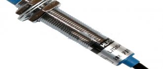
The basic principle of operation of a digital wattmeter is to preliminary measure the current and voltage in the test section of the circuit. A current sensor is connected in series to the load consumer, and a voltage sensor is connected in parallel. The main structural element of the sensor is a thermistor, thermocouple or measuring transformer.
A household wattmeter, widely used at home, works on the same principle. Such a device just needs to be plugged into a power outlet to start the measurement process.
The basis of the device is a microprocessor, which receives the measured parameters of current and voltage, after which the power is calculated. The results obtained are displayed on the screen and simultaneously transmitted to external devices. The microprocessor itself contains elements, including microcontrollers, that allow you to automatically control operating modes and remotely switch measurement limits. With their help, the symbols of the measured quantities are indicated.
When working with high and medium power level converters, calibrate the digital device using a DC power calibrator. Self-calibration of the wattmeter is carried out by an AC power calibrator. All components and elements are powered through a DC power source built inside the measuring device.
The voltage coming from the receiving converter, plugged into the socket, is amplified by the DC amplifier - DC amplifier - to values that make the operation of the ADC - analog-to-digital converter unit - more stable. Next, the voltage proportional to the measured power is converted into a time interval filled with pulses of the reference frequency.
The number of these pulses, proportional to the measured power, will be displayed on the digital readout device. The received data can be entered into a special device designed for information processing.