How does a current transformer work?
During the operation of energy systems, issues related to the need for any established electrical quantities in similar quantities with changed values in a certain proportion are often resolved. To do this, you need to know how a current transformer works, the operation of which is based on the law of electromagnetic induction, applied to electric and magnetic fields. During operation, the primary value of the current vector flowing in the power circuit is converted into a secondary current with a reduced value. During such a transformation, modulus proportionality and accurate angle transfer are maintained.
Faraday's law
According to the law of electromagnetic induction, an EMF voltage is created in the secondary winding. Calculated using the formula – U2 = −N2*dΦ/dt.
Reference! Faraday is the fundamental law of electrodynamics. It states that the generated electromotive force is equal to the rate of change of magnetic flux, but taken with a minus sign. It was Michael Faraday who made the discovery when, during experiments, he announced that electromotive force begins to appear in a conductor only when the magnetic field changes. The magnitude of this force is directly proportional to the rate of change of the magnetic field.
All the facts are contained in one equation. However, the minus sign in the law is Lenz’s rule, indicating the occurrence of an inductive electric current when the magnetic field in the conductor changes. The action of the current is directed towards the magnetic field, which begins to counteract the change in magnetic flux.
Lenz's rule does not obey the laws of electrodynamics, because induction current appears both in windings and in solid metal blocks.
In what mode does the current transformer operate?
The transformer can operate in several modes. One of them is the no-load mode, in which the secondary winding is in an open state. The current consumption of the primary circuit is minimal, which is why it is called no-load current. The no-load magnetic field is formed around the primary winding. This mode is considered absolutely harmless to the transformer.
The main one is the load mode into which the transformer goes from no-load mode. In the secondary winding, a current begins to flow, creating a magnetic flux directed against the magnetic field in the primary winding. At the first moment, the value of this magnetic flux decreases, which leads to a decrease in the self-induction emf in the primary winding.
Since the external voltage applied to the generator does not change, this leads to an imbalance in the electrical equilibrium between the applied voltage and the self-induced emf, and the current in the primary winding increases. Accordingly, the magnetic flux increases, as well as the electromotive force of self-induction. However, the current in the primary winding will be higher than in idle mode. Thus, the sum of the magnetic fluxes of the primary and secondary windings in load mode will be equal to the magnetic flux of the primary winding of the transformer in no-load mode.
In load mode, when a secondary current appears, the primary current increases. This leads to a voltage drop in the secondary winding and its reduction. In the case of a decrease in load, at which the secondary current decreases, the demagnetizing effect of the secondary winding also decreases. There is an increase in the magnetic flux in the core and a corresponding increase in the self-induction EMF. This process regarding electrical balance continues until it is completely restored.
One of the main ones is the short circuit mode, in which there will be practically zero resistance in the secondary circuit. The current in the secondary circuit reaches its maximum value, the magnetic field in the secondary winding will also have the highest value. At the same time, the magnetic field in the primary winding decreases and becomes minimal. Consequently, there is a decrease in inductive reactance in this winding. At the same time, the current consumed by the primary circuit increases. This situation leads to a short circuit, which is dangerous not only for the transformer itself, but also for the entire circuit. Short circuit protection is provided by installing fuses in the primary or secondary circuit.
Features of current transformer operation in different conditions:
- The operating mode approaches a short circuit, since the resistance of the load connected together with the secondary winding is minimal. In fact, the current transformer operates in short circuit mode.
- The current transformer differs significantly in its mode of operation from other transformer devices. When the load changes in a conventional transformer, the value of the magnetic flux in the core does not change, provided that the voltage is constantly applied.
Voltage transformers purpose and principle of operation
Voltage transformers are designed to convert the energy of a voltage source into a voltage with the desired value (amplitude). It should be noted that such transformers work only with alternating voltage and its frequency remains unchanged.
Why do you need a voltage transformer?
Voltage transformers, due to their versatility, are needed in power supplies, signal processing devices, transmission devices, power transmission devices and many other equipment.
Based on the transformation ratio, these devices can be divided into 3 types:
- step-down voltage transformer – the device output voltage is lower than the input voltage (n>1), for example, used in power supplies;
- step-up transformer – the device output voltage is higher than the input voltage (n<1), for example, used in tube amplifiers;
- matching - the transformer does not change the voltage parameters, only galvanic isolation of the circuits occurs (n~1), for example, it is used in audio amplifiers.
The operation of a transformer is based on the principle of electromagnetic induction and for the most complete transfer of energy and to reduce losses during transformation, the device is usually made on a magnetic core.
As a rule, there is one primary coil, but there can be several secondary coils, it all depends on the purpose of the transformer.
How does a voltage transformer work?
After an alternating voltage U1 appears in the primary winding, an alternating magnetic flux Ф appears in the magnetic circuit, which excites voltage in the secondary winding U2. This is the simplest and most concise description of the operating principle of a voltage transformer.
The most important parameter of transformers is the “transformation ratio” and is denoted by the Latin “n”. It is calculated by dividing the voltage in the primary winding by the voltage in the secondary winding or the number of turns in the first coil by the number of turns in the second coil.
This coefficient allows you to calculate the required parameters of your transformer for the selected device. For example, if the primary winding has 2000 turns and the secondary winding has 100 turns, then n=20. With a network voltage of 240 volts, the output of the device should be 12 volts. You can also determine the number of turns at given input and output voltages.
In what mode does the voltage transformer operate?
The most important elements of high-voltage circuits are voltage measuring transformers. These devices are designed to reduce high voltage, after which the reduced voltage can power measuring circuits, relay protection, automation and metering, as well as other elements. Thus, voltage transformers make it possible to measure voltage in high-voltage networks; they supply power to the coils of minimum voltage relays, meters, wattmeters, phase meters, as well as to equipment that monitors the state of network insulation.
Using a transformer, the high voltage is reduced to standard values. With their help, the measuring circuits and relay protection are separated from the primary high-voltage circuits. The primary winding is connected to the input voltage source of the network, and the secondary winding is connected in parallel to the coils of relays and measuring instruments. The voltage transformer operates in a mode close to idle. This is due to the high resistance of devices connected in parallel and the low current consumed by them.
To ensure normal operation of secondary circuits, the installation of voltage transformers can be carried out not only on substation buses, but also at each connection point. Before starting electrical installation work, it is necessary to inspect the device, check the integrity of the insulation, the serviceability of components and elements. For the purpose of further safe operation of the transformer, its housing and secondary winding are grounded. As a result, protection is created against the possible transfer of high voltage to secondary circuits in the event of an insulation breakdown.
Each transformer has a certain rated error and accuracy classes of 0.2; 0.5; 1; 3. The level of error depends on the design of the magnetic circuit, the size of the secondary load and other factors. You can compensate for the voltage error by reducing the number of turns of the primary winding and compensating for the angular error with special compensating windings.
Source
Classification of voltage transformers
TNs are classified according to the following parameters:
- primary winding voltage (3, 6, 10 ... 750 kV)
- voltage of the main secondary winding (100 V - for single-phase, connected between phases, three-phase; 100√3 - single-phase, connected between phase and ground voltage of the additional secondary winding (100V - single-phase in a network with a grounded neutral, 100√3 - single-phase in a network with isolated neutral
- number of phases (single-phase, three-phase)
- number of windings (two-winding, three-winding)
- accuracy class (0.1 0.2 0.5 1 3 3Р 6Р)
- cooling method (dry, oil, gas-filled)
- insulation (air-paper, cast, compound, gas, oil, porcelain)
For voltages of 6 and 10 kV, cast transformer transformers filled with epoxy resin are used. These devices are installed in switchgears. They take up smaller dimensions compared to oil ones. Their advantages also include less maintenance.
Operating principle of CTs and their purpose
In today's material, I decided to start considering issues related to the basics of the theory of current transformers. These devices themselves are ubiquitous in electrical installations, and I think everyone will find it interesting and useful to update their memory on the principle of their operation.
Purpose of current transformers: current conversion and circuit separation
Let's start by answering the question - what is a current transformer for? There are several main issues that the installation of current transformers solves.
- Firstly, this is the measurement of large currents, when directly measuring the real value of the primary current is not possible. The value converted downwards after the current transformer is measured. This is usually 1, 5 or 10 amps.
- Secondly, this is the separation of primary and secondary circuits. Thus, the insulation of relay equipment, electricity meters, and measuring instruments is protected.
What does a TT consist of, the principle of its operation
The current transformer has a closed core (magnetic core), which is assembled from sheets of electrical steel. There are two windings on the core: primary and secondary.
The primary winding is connected in series (in a cut) of the circuit through which the measured (primary) current flows. Series-connected relays and devices are connected to the secondary winding, which form the secondary load of the current transformer. This description of the composition of the current transformer is sufficient to describe the principle of its operation; a more detailed description of the actual composition of the current transformer is given in another article.
To consider the principle of operation of a current transformer, consider the diagram located in the figure.
Current I1 flows in the primary winding, creating magnetic flux F1. An alternating magnetic flux F1 crosses both windings W1 and W2. When crossing the secondary winding, the flow F1 induces an electromotive force E2, which creates a secondary current I2. Current I2, according to Lenz's law, has the direction opposite to the direction of I1. The secondary current creates a magnetic flux F2, which is directed counter to F1. As a result of the addition of magnetic fluxes F1 and F2, a resulting magnetic flux is formed (in the figure it is designated Fnam). This flow is several percent of the F1 flow. It is the Fnam flow that is the link that carries out the transmission and transformation of current. It is called magnetization flux.
§65. Transformer operating modes and characteristics
Idle mode. When the secondary winding is open, the transformer operates in no-load mode. The no-load current i0 passing through the primary winding has two components: active i0a and reactive i0p. Wherein
Í = Í 0a + Í 0р
The reactive component is called magnetizing current; this current creates a magnetic flux in the magnetic circuit of the transformer. The active component ensures that the transformer receives the electrical energy necessary to compensate for energy losses in the steel of the magnetic core. It is small, therefore the no-load current can be considered practically equal to the magnetizing current: I0≈ I0р. When designing transformers, they strive to make the magnetic resistance of the magnetic core small so that the no-load current for powerful transformers is 3-4%, and for medium-power transformers - 8-10% of the rated current.
The emf induced in the primary and secondary windings, according to the law of electromagnetic induction, is proportional to the rate of change of the magnetic flux. Consequently, they are proportional to the maximum value of the magnetic flux Фm and the frequency of its change. In each turn of the primary and secondary windings an e is induced. d.s, the effective value of which is EB = 4.44 fft, where 4.44 = 2√2 is a constant.
Respectively:
E1 = 4.44 fω1 Ft; E2 = 4.44 f ω 2Ft
When idling e. d.s. E1 is almost equal to the supply voltage U1, since the voltage drop in the primary winding created by the small no-load current is small. If the voltage U1 changes, then the e.m. will change. d.s. E1, magnetic flux Ft and no-load current I0. Dependency e. d.s. E1 from the no-load current is called the no-load characteristic (Fig. 221, a). At low voltages U1 and e. d.s. E1, the magnetic flux of the transformer is small, and a small no-load current is required to create it. In this case, the magnetic system of the transformer is not saturated and the current I0 increases in proportion to U1 (as does the excitation current in a DC generator). With a further increase in voltage U1, the magnetic circuit of the transformer becomes saturated and the current I0 begins to grow faster than e. d.s. E1. A significant increase in voltage U1 above the nominal is unacceptable, since this sharply increases the no-load current.
Load mode. When the load ZH is connected to the secondary winding of the transformer (Fig. 222), it begins to supply some power to the load. Accordingly, the power received by the primary winding from the supply network also increases. Consequently, as the current i2 in the secondary winding increases, the current i1 in the primary winding also increases.
The magnetic flux of the transformer is determined by the value of the supply voltage U1 and is practically independent of the load. Therefore, the resulting mf s created under load is
Rice. 221. Characteristics of power and rectifier transformers: a - no-load; b— external (φ2> 0—active-inductive load, (φ2<0—active-capacitive)
Rice. 222. Diagram of magnetic fluxes in a transformer under load
kami i1 and i2 should remain the same as at idle:
F1 + F2 = F0
Where
F1=I1 ω 1 - m.d.s. primary winding under load; F2=I2 ω 2—m. d.s. secondary winding under load; F0=I0 ω 0—m. d.s. primary winding at idle.
Equation (78) is called the equilibrium equation of the magnetomotive forces of the transformer. If we divide both of its parts by ω 1, we get: Í1= Í0 - Í2 ω 2/ ω 1, which means that the presence of current I2 in the secondary winding of the transformer automatically causes an increase in current I1 in the primary winding. Typically, in high- and medium-power transformers, the current I0 is several percent of the rated current I0. Therefore, at loads close to the nominal one, we can assume that Н1 ≈ У2 ω 2/ ω 1
Currents i1 and i2, passing through the windings of the transformer, create voltage drops in them - active and reactive (inductive). Active voltage drops arise as a result of the passage of currents i1 and i2 through the active resistances R1 and R2 of the windings. Reactive voltage drops are caused by the action of leakage fluxes F?1 and F?2 created by currents i1 and i2. Unlike the main flow F, which is closed along the core and coupled simultaneously with both windings, the flows F?1 and F?2 are each coupled only with their own winding and induce e. d.s. self-induction еL1 and еL2. These e. d: s, as was shown in § 51, create inductive resistances X1 and X2 of the windings, in which voltage drops occur when currents i1 and i2 pass through.
To determine the change in the secondary voltage of the transformer under load, the voltage U2 is usually reduced to the primary, multiplying it by the transformation ratio, i.e. U'2=U'2n. In the same way, current I2 is brought to the primary winding, multiplying it by 1/n, i.e. I'2 = I'2/n. The quantities U'2 and I'2 are called reduced secondary voltage and secondary current.
The change in the secondary voltage can be determined by the external characteristic of the transformer (see Fig. 221, b), which is a graphical dependence of the reduced secondary voltage U'2 on the reduced secondary current I'2. At idle, the reduced secondary voltage U'2 will be equal to
Rice. 223. External characteristics of the welding transformer
primary U1, but under load, due to voltage drops in the resistances R1, R2, X1 and X2 of the primary and secondary windings, it will be less than U1. In medium and high power transformers, the reactive voltage drop is usually several times higher than the active one. Therefore, an active-inductive load causes a greater voltage change than an active one (the voltage change increases with decreasing cos? 2 in the load circuit). In low-power transformers, on the contrary, the active voltage drop is usually greater than the reactive voltage drop and the voltage change decreases with increasing cosφ2.
Typically, the change in voltage ?U when the transformer is operating under load is determined at the rated value of the primary voltage U1NOM and is expressed as a percentage:
Δu% = [(U1NOM - U2n) / U1NOM ] 100
The value ?u% is sometimes called the relative voltage loss in the transformer. In power and rectifier transformers, the voltage change at rated current is usually 2-6% (depending on cos?2).
Short circuit. The transformer passport does not indicate the change in voltage, which is different for different cosφ2, but the resulting voltage drop in its windings at the rated load current. This voltage drop is called the short-circuit voltage and can be determined experimentally by feeding a transformer with a short-circuited secondary winding at reduced voltage UK (short-circuit test). In this case, the voltage UK will be equal to the voltage U1 at which rated currents flow through the windings of the short-circuited transformer.
The short circuit voltage is a very important performance indicator and is expressed as a percentage of U1NOM:
uk% = (Uk / U1NOM) 100
For medium-power transformers uk% = 5-7%, for high-power transformers 6-12%.
If a short circuit occurs during operation of the transformer at the rated voltage, then large currents arise in both windings, exceeding the rated value by 10-20 times, while the temperature of the windings increases and large electromagnetic forces act on them. Such a short circuit is emergency and requires special protection, which should turn off the transformer within a fraction of a second. Steady-state short-circuit current of a transformer in the general case
Ik = Inom (100 / uk%)
where In is the rated current of the primary winding.
To limit short-circuit currents, powerful transformers are made with increased values of uk%, i.e., with increased internal inductive resistance of the windings.
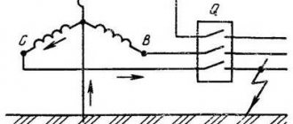
Characteristics of welding transformers. In some cases, it is desirable for the transformer to have a steeply falling external characteristic (Fig. 223). Welding transformers, for example, should have this characteristic, since it ensures stable burning of the electric arc. In addition, during electric welding, the short circuit mode is the normal operating mode, and with a steeply falling characteristic, the current Is? Inom.
To obtain a steeply falling characteristic, a reactor with high inductive reactance is connected in series with the secondary winding of the transformer (Fig. 224, a). In some designs of welding transformers, the magnetic circuit of the additional reactor is combined with the magnetic circuit of the transformer (Fig. 224, b). Regulation of the electric arc current I2 is carried out in such transformers in two ways: stepwise - by changing the number of turns of the secondary winding and smooth - by changing the air gap d. When the air gap changes, the inductance of the reactor and, consequently, the slope of the external characteristic of the transformer changes.
Rice. 224. Schematic diagrams of welding transformers: a - with external inductance (reactor), b - with a reactor on a common core; 1 - transformer; 2 - reactor
Operating modes of current transformers
TTs have two main operating modes - steady-state and transient.
In steady state operation, the currents in the primary and secondary windings do not contain free aperiodic and periodic components. In the transition mode, free damped current components pass through the primary and secondary windings.
If the CT is selected correctly, then in both operating modes the errors should not exceed those permissible in these modes, and the currents in the windings should not exceed the permissible thermal and dynamic resistance.
CTs for measurements are designed to operate in steady state, provided the permissible errors are not exceeded. The operation of the CT for protection begins from the moment the overload current or short-circuit current occurs; in these modes the requirements of certain types of protection must be met.
What is the difference between a current transformer and a voltage transformer and a power transformer?
There are differences in the operation of CT and VT.
- The primary current of the CT does not depend on the secondary load, which is typical for VTs. This is determined by the fact that the resistance of the secondary winding of the CT is an order of magnitude less than the resistance of the primary circuit and, in general, the closer it is to zero, the more accurate the device. In voltage transformers and power transformers, the primary current depends on the magnitude of the secondary load current.
- The CT always operates with a closed secondary winding and the value of its secondary load resistance does not change during operation.
- It is not allowed to operate a CT with an open secondary winding; for VT and power transformers, when the secondary winding is opened, a transition to idle operation occurs.
Bookmark or share with friends
Source
Why are voltage transformers needed?
Measuring VTs refer to electrical energy converters, which:
- transform the voltage of a network section or installation into a voltage of an acceptable value for carrying out measurements using standard measuring devices, power supply for relay protection, alarm devices, automation, telemechanics;
- by isolating secondary devices and circuits, they protect equipment from high voltage and personnel who have access to servicing electrical installations from electric shock.
The VT is connected to the high-voltage part of the electrical installation by connecting its primary winding “in parallel” to the high-voltage circuit. The rating of the secondary windings of a voltage transformer is usually 100 V. Since the resistance of the measuring instruments connected to the secondary winding is high, the current can be neglected. Therefore, the main operating mode of the transformer is similar to the no-load mode of a typical power transformer.
Current transformers - operating principle and application
When operating energy systems, there is often a need to convert certain electrical quantities into similar analogues with proportionally changed values.
This allows you to simulate certain processes in electrical installations and safely carry out measurements. The operation of a current transformer (CT) is based on the law of electromagnetic induction, operating in electric and magnetic fields that vary in the shape of the harmonics of variable sinusoidal quantities.
It converts the primary value of the current vector flowing in the power circuit into a secondary reduced value, maintaining modulus proportionality and accurate angle transfer.
Operating principle of current transformer
The diagram illustrates the processes occurring during the transformation of electrical energy inside a transformer.
Current I1 flows through the power primary winding with the number of turns w1, overcoming its total resistance Z1. A magnetic flux F1 is formed around this coil, which is captured by a magnetic circuit located perpendicular to the direction of the vector I1. This orientation ensures minimal losses of electrical energy when it is converted into magnetic energy.
Crossing the perpendicular turns of the winding w2, the flow F1 induces an electromotive force E2 into them, under the influence of which a current I2 appears in the secondary winding, overcoming the total resistance of the coil Z2 and the connected output load Zn. In this case, a voltage drop U2 is formed at the terminals of the secondary circuit.
The value of K1, determined by the ratio of vectors I1/I2, is called transformation ratio. Its value is set when designing devices and is measured in finished structures. The differences between the indicators of real models and the calculated values are assessed by a metrological characteristic - the accuracy class of the current transformer.
In real work, the current values in the windings are not constant values. Therefore, the transformation ratio is usually denoted by nominal values. For example, its expression 1000/5 means that with an operating primary current of 1 kiloampere, a load of 5 amperes will act in the secondary turns. Based on these values, the long-term operation of this current transformer is calculated.
Magnetic flux F2 from the secondary current I2 reduces the value of flux F1 in the magnetic circuit. In this case, the transformer flux Фт created in it is determined by the geometric summation of vectors Ф1 and Ф2.
Hazardous factors when operating a current transformer
Possibility of injury from high-voltage potential during insulation breakdown
Since the CT magnetic circuit is made of metal, has good conductivity and magnetically connects the insulated windings (primary and secondary), there is an increased risk of electrical injury to personnel or damage to equipment if the insulating layer is damaged.
In order to prevent such situations, grounding of one of the secondary terminals of the transformer is used to drain high-voltage potential through it in case of accidents.
This terminal is always marked on the device body and is indicated on the connection diagrams.
Possibility of injury from high-voltage potential when the secondary circuit breaks
The terminals of the secondary winding are marked “I1” and “I2” so that the direction of the flowing currents is polar and coincides across all windings. When the transformer is operating, they must always be connected to the load.
This is explained by the fact that the current passing through the primary winding has a power (S=UI) of high potential, which is transformed into a secondary circuit with low losses and when there is a break in it, the current component sharply decreases to the values of leakage through the environment, but at the same time the drop increases significantly stress on the broken section.
The potential at the open contacts of the secondary winding during the passage of current in the primary circuit can reach several kilovolts, which is very dangerous.
Therefore, all secondary circuits of current transformers must always be reliably assembled, and shunt short circuits must always be installed on windings or cores that are taken out of service.
Design solutions used in current transformer circuits
Any current transformer, as an electrical device, is designed to solve certain problems during the operation of electrical installations. The industry produces them in a large assortment. However, in some cases, when improving designs, it may be easier to use ready-made models with proven technologies than to re-design and manufacture new ones.
Current transformer parameters
Knowing, by definition, that these parts serve for measurements and protective functions, one can guess that their main characteristics will be: KI and accuracy class.
Transformation coefficient KI
Transformer units only perform scaling of electricity parameters, they do not produce it themselves. To determine the amount of scaling, the transformation ratio is used.
The relationship between the amount of current (I) or voltage (U) applied to the input and removed at the output is called the transformation ratio (CT).
In the case of current conversion, we are talking about:
КI = I2/I1,
Where:
- КI – CT transformation coefficient;
- I1 – input current;
- I2 – output current.
For CTs, a proportional relationship is observed between the primary and secondary currents. This follows from the expressions:
- I1 =I2 / KI;
- I2 = I1 * KI.
Clarification. The nominal Ctr of the CT is displayed as a fractional expression. The numerator is the rated value of the current flowing in the primary coil, the denominator is the rated current value in the secondary electrical winding. It is always greater than one.
Thus, the nominal value of the measured current reflects KI nom. The specified passport data of the part (KI = 65/5) indicates that when 65 A is passed through the primary coil, a current of 5 A will flow in the secondary coil.
Specifying values on the part nameplate
When using CTs, the current in the secondary circuit is reduced, which makes it possible to ensure safe operation. The secondary circuit includes not only measuring equipment that records the current value, but also protection or automatic switching systems. In this case, KI < 1.
For voltage values, the coefficient formula is different:
KU = U2/U1.
The scaling changes (sign) depend on the value of K. When K>1, the transformer increases the supplied electrical value, and when K<1, it decreases it.
If the inductive coupling between the two windings of the transformer remains unchanged, then the conversion coefficient can be changed by changing the ratio of the number of turns of winding wire in coils W1 and W2. Referring to his formula:
KU = U2/U1,
it can be equated to the following form:
KU = W2/W1,
Where:
- KU – transformation coefficient;
- W2 – number of turns of coil No. 2;
- W1 – number of turns of coil No. 1.
The diameter of the wound wire depends on the amount of current planned to pass through the winding.
Accuracy class
This is the main characteristic of the CT, affecting the metrology of the process. The accuracy class depends on two errors:
- current error (%);
- angular error (min).
The first option, when the actual KId. differs from the nominal KIn coefficient.
The error formula looks like:
f = (I2d – I2n)/ I2n * 100%,
Where:
- f – current error;
- I2d – secondary real (real) current;
- I2н – secondary rated current.
The angular error is the angle between the current vectors: primary and secondary. Moreover, the secondary current vector is rotated by 1800.
Attention! These errors are motivated by the influence of magnetizing currents. Accuracy classes are selected from the 0.2 line; 0.2S; 0.5; 0.5S and other values according to GOST 7746-2015
Design and principle of operation
The appearance of a typical current transformer is shown in Figure 1. A characteristic feature of these models is the presence of a dielectric housing. Case shapes can be different - from rectangular to cylindrical. Some designs do not have pass-through bars in the center of the body. Instead, a hole was made to wrap around the wire, which serves as the primary winding.
Rice. 1. Current transformer
Dielectric materials are selected depending on the voltage for which the device is intended and on its operating conditions. To service industrial energy systems, powerful CTs with cylindrical ceramic housings are manufactured (see Fig. 2).
Rice. 2. Industrial ceramic current transformer
A feature of the transformer is the mandatory presence of a load element (resistance) in the secondary winding (see Fig. 3). The resistor is necessary in order to prevent operation in mode without secondary loads. The operation of a current transformer with unloaded secondary windings is unacceptable due to strong heating (up to destruction) of the magnetic circuit.
Transformers. Operating modes
A transformer, like any electromagnetic device, has several stable modes in which it can (and should) operate indefinitely.
Transformer operating modes
There are five characteristic operating modes of the transformer:
- Work mode;
- Nominal mode;
- Optimal mode;
- Idle mode;
- Short circuit mode;
Work mode
The mode is characterized by the following features:
- The voltage of the primary winding is close to or equal to the rated value (dot_1 ≈ dot_<1nom>);
- The primary winding current is less than or equal to its rated value (dot _1 ≤ dot _1nom).
Most transformers are used in operating mode. For example, power transformers operate with winding voltages and currents different from the rated ones. This is due to the variable nature of their workload.
Measuring, pulse, welding, separating, rectifying, booster and other transformers are also usually operated in operating mode simply because the voltage of the network to which they are connected differs from the nominal one.
Nominal operating mode
Characteristic features of the regime:
- The voltage of the primary winding is equal to the rated voltage (dot_1 = dot_<1nom>);
- The primary winding current is equal to the rated current (dot _1 = dot _<1nom>).
The nominal operating mode is a special case of the operating mode. All transformers can operate in this mode, but as a rule, with larger losses compared to the operating mode and, as a result, with lower efficiency (efficiency factor). Because of this, it is avoided when operating a transformer.
Optimal operating mode
The mode is characterized by the condition:
Where (P_<хх>) - no-load losses; (P_<кз>) — short circuit losses; (k_<ng>) - transformer load factor, determined by the formula:
Where (P_2) is the load current of the secondary winding; (P_<2nom>) - rated current of the secondary winding.
In optimal operating mode, the transformer operates with maximum efficiency, so expression (1) essentially represents the condition for maximum efficiency [2, p. 308] (See “Transformers. Optimal operating mode”).
Idle mode
Characteristic features of the regime:
- The secondary winding of the transformer is open or a load with a resistance much greater than the rated load resistance of the transformer winding (1) is connected to it;
- Voltage is applied to the primary winding (dot_ <1хх>= dot_<1nom>);
- Secondary winding current (dot _2 ≈ 0) (for a three-phase transformer - (dot _ <2ph>≈ dot _ <2l>≈ 0).
Figure 1 shows a diagram of the no-load experiment of single-phase, and Figure 2 - three-phase two-winding transformers.
Figure 1 - Diagram of the no-load test of a single-phase two-winding transformer
Figure 2 - Diagram of the no-load test of a three-phase two-winding transformer
Essentially, in no-load mode, the transformer is a coil on a magnetic circuit to which a voltage source is connected. The no-load mode is operational for voltage transformers. In addition, this mode serves to determine the current (i_х), power (ΔQ_хх) of idle speed and a number of other parameters [2, p. 291][3, p. 207] (see “Transformer no-load experience”).
- Note
- The resistance of the rated load of the winding is understood as a value (R_<Nom>) equal to the ratio of the rated voltage of the winding (U_<nom>) to its rated winding current (I_<nom>)
:
Short circuit mode
The short circuit mode is characterized by:
- The secondary winding is short-circuited or a load with a resistance much less than the internal resistance of the transformer is connected to it;
- A voltage value (dot_1) is applied to the primary winding such that the current of the primary winding is equal to its rated current (dot _1 = dot _<1nom>)
- Secondary winding voltage (dot_2 = 0) (for a three-phase transformer - (dot_ <2ph>= dot_ <2l>= 0).
The short circuit experiment diagram is shown in Figure 3 for single-phase, and in Figure 4 for three-phase two-winding transformers.
Figure 3 — Scheme of short-circuit experiment of a single-phase two-winding transformer
Figure 4 — Scheme of short-circuit experiment of a three-phase two-winding transformer
Short circuit mode is an operating mode for current transformers and welding transformers, while at the same time it is an emergency mode for other transformers. It is also used to determine the voltage (u_k), power (ΔP_kz) of a short circuit and other parameters of the transformer [2, p. 294][3, p. 209] (see “Transformer short circuit experience”).
Classification
The family of current transformers is classified according to several criteria.
- By purpose:
- protective;
- lines of measuring current transformers;
- intermediate (used to equalize currents in differential protection systems);
- laboratory
- By installation method:
- external (see Fig. 8), used in outdoor switchgear;
- internal (located in the closed switchgear);
- built-in;
- overhead (often combined with bushings);
- portable.
Rice. 8. Example of outdoor use of TT
- Classification according to the type of primary winding: multi-turn, which includes coil structures, and transformers, with windings in the form of loops;
- single-turn;
- tire
- Up to 1 kV;
- Over 1 kV.
Current transformers can be classified according to other criteria, for example, by type of insulation or by the number of transformation stages.
Voltage and current instrument transformers
Devices operating under high voltage require periodic measurements.
For these purposes, measuring devices that:
- reduce the voltage to the desired level;
- provide galvanic isolation of measuring equipment from circuits with increased danger.
Explanation of markings
Each type of transformer is assigned alphanumeric symbols, by which its main parameters can be determined:
- T - current transformer;
- P is a letter indicating that we have a pass-through transformer. The absence of the letter P indicates that the device belongs to the class of reference CTs;
- B - indicates that the transformer is built into the structure of the oil switch or into the mechanism of another device;
- VT - built into the design of the power transformer;
- L—with resin (cast) insulation;
- FZ is a device in a porcelain case. Link type of primary winding;
- F - with reliable porcelain insulation;
- Ш - tire;
- O - single-turn;
- M - small-sized;
- K - reel;
- 3 - used for protection against the consequences of a ground fault;
- U - reinforced;
- N - for outdoor installation;
- R - with a core intended for relay protection;
- D - with a secondary coil designed to supply electricity to differential protection devices;
- M - oil-filled. Used for outdoor installation.
- The rated voltage (in kV) is indicated after the letter symbols (first digit).
- Numbers separated by a fraction indicate the accuracy classes of the cores. Some manufacturers put the letters P or D instead of numbers.
- the next two digits “separated by a fraction” indicate the parameters of the primary and secondary currents;
- after the position of fractional symbols - the code of the design option;
- letters located after the design option code indicate the type of climate control;
- The number in the last position is the placement category.
Connection diagrams
The primary coils of current transformers are connected in series in the circuit. Secondary coils are designed to connect measuring instruments or are used in relay protection systems.
The secondary circuit includes the terminals of measuring instruments and relay protection devices. To ensure safety, the magnetic core and one of the secondary coil terminals must be grounded.
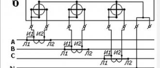
When connecting three-phase meters, in networks with an isolated neutral, the transformer windings are connected according to the “Partial star” circuit. If there is a neutral wire, a full star circuit is used.
Transformer terminals are marked. For the primary winding, the designations L1 and L2 are used, and for the secondary winding - I1 and I2. When connecting measuring instruments, the polarity of the windings must be observed.
The "partial star" circuit is used for a two-phase connection.
In differential protection used in power transformers, the windings are connected in a delta.
Basic connection diagrams:
Basic connection diagrams
- In networks with a solidly grounded neutral, the CT is connected to each phase. The connection of the transformer windings is a full star.
- Connection according to a partial star circuit. Used in networks with isolated zero points.
- Eight diagram. Symmetrically distributes loads during a three-phase short circuit.
- CT connection to a zero-sequence current filter. Used to protect the rated load from short circuits to ground.
Device and principle of operation
Structurally, the VT is not particularly different from other types of converting devices. His device:
- magnetic core laminated from electrical steel plates;
- primary coil;
- one or two secondary windings;
- protective casing (for outdoor structures).
For the appearance and schematic representation of the product, see Fig. 1. The picture shows a device with one (main) secondary winding. Some models have an additional secondary winding, which can be used, for example, to connect measuring instruments.
Please note that there is no galvanic connection between the terminals of the primary windings and the secondary coils. This is the main difference between instrument transformers and the design of a conventional step-down transformer.
Protective covers are made from different materials. In models used to service high-voltage power lines, dielectrics made of porcelain are used (Fig. 2),
To cool the windings of such high-voltage units, special transformer oils are used.
In medium-power networks, models with housings based on epoxy resins are used (Fig. 3).
Three-phase voltage transformers with zero leads are made on a magnetic core with five rods. This design protects the windings from overheating, since during single-phase short circuits in the circuits of high-voltage wires, the chain of lines of the total magnetic flux in the transformer itself is closed along the steel core.
The principle of operation also differs little from the operation of a power step-down transformer. The magnetic flux arising in the primary coil propagates along the magnetic circuit, causing an EMF voltage in the secondary winding. The voltage value depends on the ratio of the number of turns in the coils. Since the secondary windings consist of a small number of turns, the output voltage is small (usually it does not exceed 100 V).
The principle of operation of the VT is explained by the diagram in Figure 4.
An important task in the manufacture of transformers of this type is to meet the requirements for achieving the required amplitude and angular parameters of the sinusoid, which determine the corresponding accuracy class: 0.5; 1; 3. In reference samples, an accuracy class of 0.2 is used. For measuring instruments, it is important that the accuracy class is as high as possible. The higher it is, the smaller the measurement error of the device.
The accuracy of the parameters of the converted alternating currents depends on the load. The higher the load of the secondary circuit, the greater the error of the voltage transformer (the accuracy class decreases). Optimal voltage parameters at the transformer output are achieved at rated loads. In this mode, the current conversion efficiency increases as it approaches the rated transformation ratio.
The operation of VT is effective at low rated powers in secondary circuits. For these devices, prolonged idling is the norm. Therefore, they are effectively used in line protection systems that are in standby mode most of the time and consume little current.
Technical specifications
A very important characteristic of a current transformer is its accuracy class. This parameter characterizes the measurement error, that is, it shows how much the nominal (ideal) transformation ratio differs from the real one.
Transformation ratio
Since the real transformation ratio contains an in-phase and quadrature component, the coefficient values always differ from the nominal one. The difference (error) must be taken into account when measuring. Angular errors also affect the measurement results.
All CTs have a negative error, since they always have losses from magnetization and heating of the current coils. In order to eliminate the negative sign of the error, a turn correction is used to shift the transformation parameters in the positive direction. Therefore, in adjusted devices, the usual formula for calculations does not work. Therefore, manufacturers determine transformation ratios in such devices experimentally and indicate them in the technical passport.
Accuracy class
Current errors distort the accuracy of electrical current measurements. Therefore, for instrument transformers there are high requirements for the accuracy class:
- 0,1;
- 0,5;
- 1;
- 3;
- 10P.
A transformer can be within the declared accuracy class only if the maximum load resistance does not exceed the rated one, and the current in the primary circuit does not exceed the limits of 0.05 - 1.2 of the rated current of the transformer.
CLASSIFICATION AND DESIGN OF VOLTAGE TRANSFORMERS
The design of the transformer depends on what electrical networks it is intended to operate in, where it is intended to be installed, and what devices will be connected to it.
Classification of voltage transformers can be made according to the following criteria:
- voltage class for which the primary winding is designed;
- single-phase or three-phase version;
- secondary U value;
- total number of windings - two-winding or three-winding;
- accuracy class, the value of which can be 0.1, 0.2, 0.5, 1, 3, 3Р, 6Р;
- type of insulation - dry, cast, oil-filled;
place of intended installation - external or internal installation.
The secondary value of U in a VT is unified; its value depends on the connection diagram of the primary winding. Three-phase and single-phase transformers connected to the phases of the primary network produce 100 volts at the output. Single-phase VTs, when switched on to phase voltage, have 100/√3 volts on the low side.
The type of insulation and the method of heat cooling during the manufacture of transformers are selected in the same way as for power transformers.
Dry or cast insulation can be used in devices up to 35 kV; in other cases, only oil-filled structures are used.
The windings and magnetic system of an oil-filled transformer are placed in a steel tank filled with transformer oil. In this case, oil plays the role of an insulator and removes heat to the walls of the tank and into the surrounding space.
Most often, the tank has the shape of a cylinder, at the upper end of which porcelain bushing insulators are installed. Insulators are VT inputs.