Direct start
It involves connecting the stator windings to the electrical network without “intermediaries”. Suitable for motors with squirrel-cage rotor. These are low-power motors in which, when the stator windings are connected directly to the electrical network, the resulting starting currents do not cause overheating, which can damage the equipment.
In asynchronous motors, the ratio of winding inductance to resistance (L/R) is small. And the smaller the power of the device, the smaller it is. Therefore, during startup, the resulting free current quickly decays and can be neglected. Only the current strength that is established as a result of the transient process will be taken into account.
figure (a) is a diagram of a magnetic starter, indicated by the letter K. Technically, this is an electromagnetic switch, often used when starting squirrel-cage electric motors. It is necessary for automatic acceleration according to a natural mechanical characteristic (denoted by M ) from the beginning of the launch (point P ) until the moment when M becomes equal to the moment of resistance ( Ms ).
Picture (b) shows a graph of the starting current versus the initial torque. Based on it, the acceleration acceleration is equal to the difference between the abscissas of the graphs M and M(c) . In this case, if Mstart is less than Ms , then the electric motor will not be able to accelerate. Mstart value for acceleration for a motor with a squirrel-cage rotor, use the formula (slip coefficient s is equal to unity):
The ratio of Mstart to the nominal ( Mnom ) is a value defined as a multiple of the initial torque. Denoted kpm . The coefficient for engines with a squirrel-cage rotor is in the range from 1 to 1.8 and is established by GOST.
Example. If kpm = 1.4, and Mnom = 5000 N*m, then direct start should begin with MP = 7000 N*m.
Attention! The standards established by GOST must not be exceeded. This leads to an increase in active resistance on the rotating element of the motor.
Direct engine starting has the following advantages:
- Cheapness;
- Simplicity;
- Minimal heating of the windings during startup.
Disadvantages of the method:
- The value of Mstart is up to 300% of Mnom ;
- The starting current is up to 800% of the rated current (see graphs below).
Even with the listed disadvantages, direct starting remains the most preferable for asynchronous electric motors with a squirrel-cage rotor, because provides high energy performance.
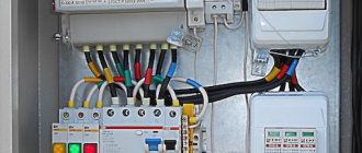
Preparing an asynchronous electric motor for switching on
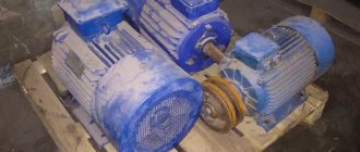
Types of electric motors
At the very first stage, we should decide on the type of motor that we are going to connect. This could be a three-phase asynchronous motor with a squirrel cage or wound rotor, a two- or single-phase motor, or maybe even a synchronous machine.
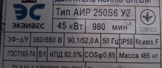
A tag on the electric motor, which contains the necessary information, can help with this. Sometimes this can be done purely visually - since we are considering the connection of three-phase electrical machines, a motor with a squirrel-cage rotor does not have a commutator, but a machine with a wound rotor has one.
Determining the beginning and end of the winding
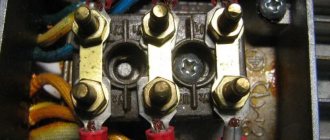
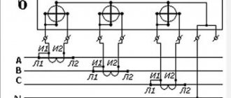
A three-phase asynchronous electric motor has six terminals. These are three windings, each of which has a beginning and an end.
For correct connection we must determine the beginning and end of each winding. There are many options for how to do this - we will focus on the simplest of them, applicable at home.
Motor stator windings
- In order to determine the beginning and end of the winding of a three-phase motor with our own hands, we must first determine the terminals of each individual winding, that is, determine each individual winding.
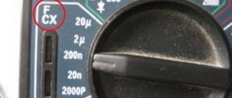
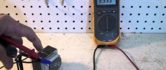
- This is quite easy to do. Between the end and the beginning of one winding we will definitely have a circuit. Either a two-pole voltage indicator with the appropriate function, or a regular multimeter will help us determine the circuit.
- To do this, connect one end of the multimeter to one of the terminals and touch the other five terminals in turn with the other end of the multimeter. Between the beginning and the end of one winding we will have a value close to zero, in resistance measurement mode. Between the other four pins the value will be practically infinite.
- The next step is to determine their beginning and end.
EMF for various types of connection of electric motor windings
- In order to determine the beginning and end of the winding, let's dive a little into the theory. The stator of an electric motor has three windings. If you connect the end of one winding to the end of another winding, and apply voltage to the beginning of the windings, then at the connection point the EMF will be equal to or close to zero. After all, the EMF of one winding compensates for the EMF of the second winding. In this case, no EMF will be induced in the third winding.
- Now let's look at the second option. You have connected one end of the winding to the beginning of the second winding. In this case, an EMF is induced in each of the windings, resulting in their sum. Due to electromagnetic induction, an EMF is induced in the third winding.
Scheme for determining the beginning and end of the motor windings
- Using this method we can find the beginning and end of each of the windings. To do this, connect a voltmeter or a light bulb to the terminals of one winding. And we connect any two terminals of other windings to each other. We connect the two remaining terminals of the windings to a 220V electrical network. Although you can use lower voltage.
- If we connect end and end of two windings, then the voltmeter on the third winding will show a value close to zero. If we connected the beginning and end of the two windings correctly, then, as the instructions say, a voltage from 10 to 60V will appear on the voltmeter (this value is very arbitrary and depends on the design of the electric motor).
- We repeat a similar experiment twice more until we accurately determine the beginning and end of each winding. To do this, be sure to sign each result obtained so as not to get confused.
Selecting a motor connection diagram
Almost any asynchronous electric motor has two connection options - star or delta. In the first case, the windings are connected to phase voltage, in the second to linear voltage.
The electric motor is three-phase asynchronous and the star-delta connection depends on the characteristics of the winding. This is usually indicated on the engine tag.
Ratings on the motor label
- First of all, let's figure out what is the difference between these two options. The most common is the star connection. It involves connecting all three ends of the windings to each other, and voltage is applied to the beginning of the windings.
- With a delta connection, the beginning of each winding is connected to the end of the previous winding. As a result, each winding turns out to be a side of an equilateral triangle - hence the name.
Difference between star and delta connections
- The difference between these two connection options is the engine power and starting conditions. With a delta connection, the motor is able to develop more power at the shaft. At the same time, the starting moment is characterized by a large voltage drop and large inrush currents.
- In domestic conditions, the choice of connection method usually depends on the available voltage class. Based on this parameter and the nominal parameters indicated on the motor plate, the method of connecting to the network is selected.
Undervoltage starting
Suitable for starting high-power electric motors, but also optimal for medium-power analogues if the voltage in the operating network does not allow accelerating the motor using direct starting.
There are three ways to reduce voltage:
- Switching the stator windings from triangle (normal circuit) to star (starting circuit). Starting starts from star, and when the rated frequency is reached, it switches to delta. In this case, the voltage supplying the phases of the stator windings drops by 1.73 times. This allows phase currents to decrease by the same amount, and linear currents are reduced by three times.
- Starting with additional resistance leading to a drop in voltage on the stator winding (Figure a). At the time of start-up, reactors or resistors are included in the electrical circuit (reactive and active resistance, respectively).
- Start with connection via a step-down transformer with several automatically switched stages (Figure b).
The main advantage is the ability to accelerate the engine at almost the same voltage that is necessary for normal operation. The only disadvantages include a drop in MP and Mmax (maximum moment). These values are directly proportional to the voltage: the lower the Volt, the smaller the torque. Therefore, the motor will not start with a load.
Wound rotor motor
The phase-type rotor is not fundamentally different in winding from the stator. This is a three-phase winding, the ends of which are connected in a star configuration. The free ends of the windings are connected to current collector rings. The rings are in contact with the conductor through brushes and therefore it is possible to install an additional limiting resistor in the connection circuit.
The resistor, as a soft starter, serves to make it possible to reduce the values of the starting current, which can reach quite large values.
Connecting the rotor to the rheostat during switching on
The method is suitable for switching on motors with a wound rotor. If the rotor circuit includes a rheostat, then the active resistance increases. In this case, point K in figure a below moves closer to O and is designated K` . This does not lead to a decrease in Mmax , but it does provide an increase in Mstart . At the same time, the critical slip increases, and the dependence of the moment on s shifts to the zone of large slips. The number of revolutions shifts to the zone of lower rotational frequencies (Figures b and c).
Typically, the rheostat used to start the motor has from 3 to 6 stages (see figure a below). The starting resistance gradually decreases, which ensures a large Mstart . Initially, the motor is driven according to the fourth characteristic, illustrated in Figure b . It matches the resistance of the starting rheostat and provides maximum starting power.
Torque ( Mvr ) decreases with increasing speed. At a certain minimum value, it is necessary to turn off part of the rheostat so that Mvr increases again to the maximum (see the third characteristic). But the revolutions are increasing, so Mvr decreases again. Then another part of the rheostat is turned off, and work on the second characteristic begins. When the rheostat of a wound-rotor motor is turned off completely, the starting process is completed. The motor continues to operate according to characteristic 1.
Launching using this method is characterized by a change in Mvr from the maximum to the minimum value. The resistance in this case decreases stepwise along a broken curved line (highlighted in bold on the graph). The rheostat parts are turned off automatically or manually.
The advantage of starting an electric motor with a wound rotor using a rheostat is the ability to turn it on at Mstart close to Mmax . Inrush currents are minimal. The change in current strength is illustrated in Figure c.
There are plenty of shortcomings. The first is the difficulty of inclusion. Secondly, this is the need to use not at all cheap motors with a wound rotor. The nature of the operation is worse than that of analogues with a squirrel-cage rotor with the same power value - this is the third disadvantage. This explains why electric motors with a wound rotor are used mainly in case of difficulties with starting other motors.
Starting a single-phase motor
To turn on an asynchronous motor powered from a single-phase network, auxiliary winding is used. It should lie perpendicular to the working stator winding. But to create a rotating magnetic field, one more condition must be met. This is the phase shift of the current flowing through the auxiliary winding relative to the current arising in the working winding.
To ensure a phase shift at the time of connection to a single-phase network, a special element is included in the electrical circuit of the auxiliary winding. This could be a resistor, capacitor or inductor. But only the first two are common elements.
After accelerating the motor to a frequency equal to the established frequency, the additional winding is turned off. This can be done manually or automatically. At the beginning, the motor operates according to a two-phase characteristic, and after setting the frequency, according to a single-phase characteristic.
Applying resistance at start
The method is applicable for asynchronous motors connected to a single-phase network and having a primary additional winding with a squirrel-cage rotor. This is the name given to a split-phase motor, the electrical circuit of which has a high active resistance.
To start a motor powered from a single-phase network, a starting resistor is needed, connected in series with the additional winding. Then the phase shift is 30 degrees. This is enough for overclocking. Below is a diagram according to which an ohmic phase shift is achieved.
Instead of a resistor, you can use an additional winding of high resistance but low inductance. In this case, the winding has few turns, which are made from wire of a smaller cross-section, in contrast to what is used for working winding.
In Russia, motors come off the assembly line connected to a single-phase network, equipped with a phase shift resistor. Their power varies in the range of 18-600 W. The motors are designed for networks with a voltage of 127, 220 or 380 Volts and alternating current with a frequency of 50 Hz.
How to prepare for connection
To correctly turn on a three-phase motor, you must remember that there are several winding connection diagrams, including:
- "Star". Some ends of the winding are connected together, and the other ends are connected to the phase wires of the network;
- "Triangle". All three windings are connected in series - the end of each winding with the beginning of the next. Mains voltage is supplied to the connection points.
You might be interested in this: Generator connection diagram
Note! To obtain the same power, a star connection requires a voltage √3 times greater than a delta connection. For engines that allow arbitrary switching of windings, the operating voltage “220/380” or “127/220” must be indicated on the nameplate. The first value refers to the delta connection, the second to the star connection.
Engine block, star connection
In such electric motors, the beginning and ends of all windings are connected to the terminal block in pairs in three rows:
- the beginning of the first winding - the end of the second;
- the beginning of the second - the end of the third;
- the beginning of the third - the end of the first.
Motor block, delta connection
For a star connection, connect one row of three terminals with two jumpers, and for a delta connection, close each pair with three jumpers.
Using a capacitor
The method differs from the previous one in that a split-phase motor, when connected to a single-phase line, has a high resistance only at the time of start-up.
To ensure the highest value of Mstart, a circular and rotating magnetic field is required. To do this, the currents in the working and additional windings are shifted by 90 degrees. Only a capacitor can provide such a bias. Its use helps to achieve good starting performance of an asynchronous motor powered from a single-phase electrical network.
The choice of starting method for an asynchronous electric motor depends on which network it is connected to: single-phase or three-phase. The power of the motor and its design also influence.
More on the topic: - Connection diagrams for asynchronous and synchronous single-phase motors - Connection diagrams for an electric motor via capacitors - Reversible diagram for connecting an electric motor - Do-it-yourself soft start of an electric motor - What is the difference between asynchronous and synchronous motors - Reversible connection of a single-phase asynchronous motor with your own hands - How to check an electric motor - Electric motor repair
Connection without capacitor
To connect an asynchronous motor to a single-phase network without using capacitors, there are two popular schemes. To ensure engine operation, sinistors with opposite-polar control pulses and a symmetrical dinistor are used.
The first scheme is intended for electric motors with a nominal rotation value of 1500 rpm. A special chain acts as a phase-shifting element. The connection diagram of the stator windings is a triangle.
It is necessary to create a shifted voltage across the capacitor by changing the resistance. After the capacitor voltage reaches the desired level, the dinistor will switch and include the charged capacitor in the starting circuit.
The second scheme is suitable for electric motors with high starting resistance or rated rotation speed from 3000 rpm.
Obviously, in this situation it is necessary to create a strong starting moment. It is for this reason that in machines of this type a triangle is used to connect the stator windings. Instead of phase-shifting capacitors, this circuit uses electronic switches. The first of them is connected in series to the working phase circuit, and the second in parallel. As a result of this trick, a leading current shift is created. However, this method is only effective for 120˚ electric displacement motors.