Capacitor capacity
The most significant parameter of this device is its capacity. Its scope of application, operating conditions and purpose depend on it. Capacitance is measured in farads. In domestic literature, this parameter is denoted by the letter “F”, in foreign literature – “F”. On the electronic components themselves you can find the following letter coding: pF, nF or uF. They indicate that the radio component has a capacity equal to 10-12, 10-9 and 10-6 farads. Nearby there will also be markings with numbers that act as a multiplier, i.e. 2.2uF = 2.2*10-6 farads.
Additional Information. The negative power of ten often causes difficulties even for experienced specialists. To easily convert units of measurement, you can always use an online capacitor calculator. Also, in order to calculate the capacity of an existing part, a digital multimeter with the appropriate measurement mode is suitable.
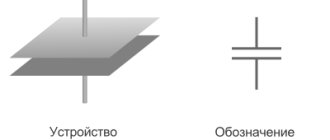
The capacitor itself is a pair of metal plates. Their transverse dimensions should be much greater than the distance between them. A dielectric layer is placed in the middle of the plates. During operation of the device, voltage is applied to its terminals. As a result, electrons try to move, but cannot overcome the dielectric, which is why some electrical charge accumulates between the plates. It is measured in coulombs. The ability of a capacitor to accumulate electrical charge is called its capacitance. If we consider the analogy with a container for liquid, then this is its volume.
Using a multimeter and formulas
If you have a multimeter with a function for measuring the “Cx” parameter, then measuring the capacitance of the capacitor is quite simple: you should switch the device to the “Cx” mode, and then select the optimal measurement range corresponding to the parameters of the capacitor. We insert the legs of the capacitor into the appropriate socket (observing the polarity of the connection) and read its parameters.
"Cx" mode in the multimeter
It is less accurate to determine the capacity using a tester that does not have the “Cx” mode. To do this, you will need a power source to which the capacitor is connected according to a simple circuit (Fig. 2).
Rice. 2. Capacitor connection diagram
The measurement algorithm is as follows:
- Measure the voltage of the power supply using the contact probes of the measuring device.
- Form an RC circuit with a capacitor and resistor terminals with a nominal value of 1 - 10 kOhm.
- Short-circuit the leads of the capacitor and connect the RC circuit to the power source.
- Measure the voltage of the formed circuit using a multimeter.
- If the voltage has changed, you need to adjust it to a value close to the one you received at the output of the power supply.
- Calculate 95% of the resulting value. Record the measurements.
- Take a stopwatch and start it at the same time as you remove the short.
- As soon as the multimeter shows the voltage value you calculated (95%), stop the stopwatch.
- Using the formula C = t/3R, where t is the time of voltage drop, we calculate the capacitance of the capacitor in farads, if the units of measurement of the resistor resistance are expressed in ohms and time in seconds.
Rice. 3. Measurement using a tester. Examination
Let us emphasize once again that the accuracy of measuring capacitance using this method is not too high, but it is quite possible to determine the performance of a radio element based on such a measurement. Some components of electronic devices work properly if there are small deviations from the nominal capacities, the main thing is that there is no electrical breakdown.
The same method can be used to calculate the parameters of a ceramic radio element. To do this, you need to connect the RC circuit through a transformer and apply alternating voltage. The value of the capacitance in this case is determined by the formula: C = 0.5*π*f*Xc, where f is the current frequency, and Xc is the capacitance.
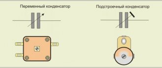
Variable capacitors
Initially, people had enough of the capacitors described above from a pair of plates. Then this device was developed. Devices in the form of balls, disks and cylinders began to appear. This was necessary in order to increase the capacitance of the capacitor C, because it is primarily related to the area of the plates S and the distance between them d. This is clearly seen from the formula. It is used to calculate the capacitance of the capacitor.
Over time, these non-standard geometric shapes ceased to satisfy the needs of experimenters. Therefore, new devices with variable capacity were developed. They have movable plates. This allows you to easily change the area of their mutual intersection, thereby affecting the value of the capacitance of the capacitor. The most common and familiar example of this electronic device is the oscillatory circuit in the radio. All people have adjusted the receiver at least once. It is this “twist” that is a variable capacitor. When it rotates, the capacitance changes, and accordingly, the resonant frequency of the oscillatory circuit of the radio receiver changes. This in turn tunes the radio to a different station.
How to correctly calculate the capacitance of a capacitor?
The simplest example of a capacitor is a flat model. It has the shape of two parallel covers made of a conductor, between which there is a dielectric layer. In order to know how to calculate the capacitance of capacitors, you need to apply the following formula:
You may be interested in this Features of the DRL 250 lamp
C = ex e0 xs / d,
where S is the surface area of the plates and d is the distance between them. In turn, this is the relative electrical permittivity of a given dielectric.
As a rule, capacitors are not used individually, but are connected to larger systems. They can be connected in series, parallel or mixed.
Capacity formula
Important! In series-connected elements, the absolute value of the charge on each plate is identical.
Thus, the resulting voltage is equal to the sum of these indicators on the individual components of the device.
The total capacity of the system will be determined by the formula:
1/С = 1/С1 + 1/С2 + 1/С3 + …
When connected in parallel, the potential difference on each part is the same. Thus, the total charge will be equal to the sum of the charges on the components of the capacitor, and the resulting capacitance will be equal to the sum of the individual unit values:
C = c1 + c2 + c3 + …
Capacitor Characteristics
In addition to capacitance, there are other parameters and characteristics of capacitors. The most important of them are:
- Rated voltage;
- capacitor type;
- permissible deviation of the nominal value;
- equivalent series resistance (ESR);
- polarity;
- and more than a dozen other less important characteristics.
It is strictly forbidden to exceed the operating voltage of the capacitor. Ideally, it is better to select a container with a voltage reserve of 1.5-2 times.
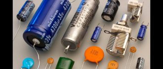
Electrical containers are made from a huge range of different materials: aluminum, tantalum, ceramics and much more. As a result, there is a wide variety of these devices: electrolytic, film, “flags”, porcelain, polymer, etc.
In some circuits it is important to use the exact capacitance, in others a significant deviation of this parameter is acceptable. Therefore, capacitors come with different permissible errors: from +/-20% up to +/-0.05%.
ESR (equivalent series resistance) is a relatively new concept. It indicates the internal resistance of the capacitor in the context of alternating and pulsed current.
Electrolytic capacitors have a polarity, i.e., when connecting them, you need to take into account where is “+” and where is “-”. Most other charge storage devices do not have this property.
Additional Information. The high level of ESR of capacitors in a light bulb with LEDs can be judged by its flickering. An LED lamp with working containers should provide continuous light.
Physical definition of a capacitor
A capacitor is an electrical element that serves to store charge or energy. Structurally, the radio element consists of two plates made of conductive material, between which there is a dielectric layer. The conductive plates are called plates. They are not connected to each other by a common contact, but each has its own terminal.
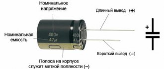
Capacitors have a multilayer appearance, in which a dielectric layer alternates with layers of plates. They are a cylinder or parallelepiped with rounded corners. The main parameter of an electrical element is capacitance, the unit of measurement of which is the farad (F, Ф). On diagrams and in literature, a radio component is designated by the Latin letter C. After the symbol, the serial number on the diagram and the value of the nominal capacity are indicated.
Since one farad is a fairly large value, the actual values of the capacitance of the capacitor are much lower. Therefore, when writing, it is customary to use conditional abbreviations:
- P - picofarad (pF, pF);
- N - nanofarad (nF, nF);
- M - microfarad (mF, µF).
Principle of operation
The operating principle of the radio component depends on the type of electrical network. When connected to the terminals of the plates of a direct current source, charge carriers fall on the conductive plates of the capacitor, where they accumulate. At the same time, a potential difference appears at the terminals of the plates. Its value increases until it reaches a value equal to the current source. As soon as this value is leveled out, charge stops accumulating on the plates and the electrical circuit is broken.
In an alternating current network, a capacitor represents a resistance. Its value is related to the frequency of the current: the higher it is, the lower the resistance and vice versa. When a radio element is exposed to alternating current, a charge accumulates. Over time, the charge current decreases and disappears completely. During this process, charges of different signs are concentrated on the plates of the device.
The dielectric placed between them prevents their movement. At the moment of half-wave change, the capacitor is discharged through the load connected to its terminals. A discharge current occurs, that is, the energy accumulated by the radio element begins to flow into the electrical circuit.
Characteristics and types
Measurements of capacitor parameters are associated with finding the values of their characteristics
But among them, the most important is capacity, which is usually measured. This value indicates the amount of charge that a radio element can accumulate
In physics, electrical capacity is a value equal to the ratio of the charge on any plate to the potential difference between them.
In this case, the capacitance of the capacitor depends on the area of the plates of the element and the thickness of the dielectric. In addition to capacity, a radio device is also characterized by polarity and the value of internal resistance. Using special instruments, these quantities can also be measured. The resistance of the device affects the self-discharge of the element. In addition, the main characteristics of the capacitor include:
- Leakage resistance. This is the internal impedance through which a capacitor not connected to an external circuit is discharged.
- Equivalent inductance. This is a parasitic characteristic that affects the operation of the element at high frequencies.
- Equivalent Series Resistance (ESR). It consists of the generalized resistance of the leads and plates, and is represented as a resistor connected in series with a capacitor.
Capacitors are classified according to different criteria, but first of all they are divided according to the type of dielectric. It can be gaseous, liquid and solid. Most often, glass, mica, ceramics, paper and synthetic films are used. In addition, capacitors differ in their ability to change the value of capacitance and can be:
- Permanent. Capacitors belonging to this type have a constant capacitance value.
- Variables. These include radioelements, the capacity of which can be changed during operation of the device. The change occurs due to changes in temperature conditions, electrical parameters of the circuit and mechanical methods.
- Construction. They allow you to change the capacity when setting up the equipment, while the element does not have to be connected to the power source.
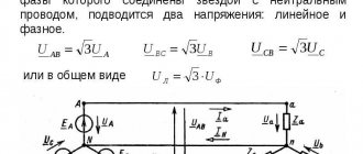
Selecting a capacitor for an electric motor
To power a 380 V motor from a single-phase 220 V network, you will need to select a working capacitor for it. If the motor power exceeds approximately 1.5 kW, a starting tank will be required.
Important! Such circuits are more suitable for turning on motors with low mechanical load on the shaft (for example, fans). For more serious units it is better to use a full three-phase network.
The selection of a working capacitor itself is very complicated. It is simplistically powerful to assume that its capacity Cp should be 70 uF for every 1 kW of the engine. That is, if the motor power is 400 W, then a 28 uF capacitor will be required.
The capacity to start the motor Cn should be approximately 2.75 more than the working one. In this case, when the engine reaches idle speed, the starting capacitor must be excluded from the circuit by contacts B2.
Practice shows that calculating capacities is not such a difficult matter. This knowledge is required by people whose profession is somehow related to electricity, especially electronics engineers. Therefore, specialists need to know exactly how and which capacitor is selected for specific purposes.
Start capacitor
Also check out these articles
- Power cable - features
- Features and importance of checking a house before purchasing
- Electricity meter Mercury 201
- Impregnation for wood for outdoor use
It is worth noting that on small electric motors used for domestic needs, for example, for a 200-400 W electric sharpener, you can not use a starting capacitor, but get by with one working capacitor, I have done this more than once - a working capacitor is quite enough. Another thing is if the electric motor starts with a significant load, then it is better to use a starting capacitor, which is connected in parallel with the working capacitor by pressing and holding the button while the electric motor accelerates, or using a special relay. The starting capacitor capacity is calculated by multiplying the working capacitor capacity by 2-2.5; this calculator uses 2.5.
It is worth remembering that as the asynchronous motor accelerates, it requires less capacitor capacity, i.e. You should not leave the starting capacitor connected for the entire operating time, because A large capacity at high speeds will cause overheating and failure of the electric motor.
formulas for capacitors
One of the important elements of the electrical circuit is a capacitor, the formulas for which allow you to calculate and select the most suitable option. The main function of this device is to accumulate a certain amount of electricity. The simplest system includes two electrodes or plates separated by a dielectric.
- What is the capacitance of a capacitor measured in?
- Capacitor Energy Formula
- Capacitor charge formula
- Capacitor Leakage Current Formula
What is the capacitance of a capacitor measured in?
One of the most important characteristics of a capacitor is its capacity. This parameter is determined by the amount of electricity accumulated by this device. The accumulation occurs in the form of electrons. The number of them placed in the capacitor determines the capacitance value of a particular device.
The unit used to measure capacitance is the farad. A capacitor's capacity of 1 farad corresponds to an electric charge of 1 coulomb, and the potential difference across the plates is 1 volt. This classical formulation is not suitable for practical calculations, since the capacitor collects not charges, but electrons. The capacity of any capacitor is directly dependent on the volume of electrons that can accumulate during normal operating conditions.
The farad is still used to denote capacitance, and the quantitative parameters are determined by the formula: C = Q / U, where C means capacitance, Q is charge in coulombs, and U is voltage. Thus, the mutual relationship between charge and voltage is visible, influencing the capacitor’s ability to accumulate and retain a certain amount of electricity.
To calculate the capacitance of a flat capacitor, the formula is used:
in which
ε = 8.854187817 x 10 -12 f/m is a constant value. Other quantities: ε is the dielectric constant of the dielectric located between the plates, S is the area of the plate, and d is the gap between the plates.
Properties and parameters of capacitors
The main parameter of devices in this category is capacity (C). It determines the storage properties of the product. The operating principle is based on the transfer of electrons to the corresponding plate when a power source is connected. Depending on the polarity, positive (negative) charges appear on the corresponding electrode.
Types of protection for sockets
The size of the capacity depends on several parameters:
- plate sizes (plating area);
- distances between them;
- dielectric properties of the material in the gap.
For your information. Capacity is indicated in multiple units. Example: pF or pF is picofarad (10-12 farads).
The voltage of a flat capacitor is calculated using the formula:
E = q/(e*e0*S),
Where:
- q – charge;
- e – dielectric constant;
- S – working area.
From this expression it is easy to conclude about the mutual influence of electrical and structural parameters. Capacity is determined as follows:
С= (e*e0*S)/ d = q/U,
Where:
- d – distance between plates;
- U – voltage.
For convenience, a specific indicator is used:
Court=C/V,
where V is the volume of the product.
Based on it, a conclusion is drawn about how effectively the capacitor performs its main functions. With a high specific capacity, discharging takes longer if a similar load is connected.
The accuracy class or percentage deviation indicates the tolerance from the nominal capacity (values are indicated ± in%):
- 5;
- 10;
- 15;
- from -20 to +30;
- from -20 to +50.
Consumer parameters of a dielectric are characterized by electrical strength. As a rule, the voltage rating in long-term operating mode for certain conditions is indicated on the product body, taking into account the ranges:
- temperature;
- relative humidity;
- pressure.
Detailed documentation indicates the breakdown voltage.
Inductance (self) changes the field strength of the capacitor. This reactive component “helps” the product discharge faster or slower compared to the design speed of the process. Such parasitic influences distort the operating characteristics of the oscillatory circuit. They must be taken into account when designing frequency-dependent circuits.
Losses are estimated by the electrical resistance of the insulating layers. If you connect the multimeter accordingly, you can clarify the actual leakage current. This parameter is measured over a certain period of time. It should be remembered that resistance depends on temperature and humidity.
For your information. Mica capacitors will discharge more slowly than paper capacitors under equal conditions, since the leakage currents differ by an order of magnitude.
For a comprehensive comparison of different parts in this category, stability is checked. This indicator characterizes the constancy of operating parameters. As a rule, the influence of temperature is taken into account. The specialized coefficient (TKE) shows the corresponding changes with an increase (decrease) of 1°C.
How to discharge a capacitor to minimize residual voltage? The answer to this question will help to obtain the study of absorption processes in the dielectric layer. The corresponding parameters are characterized by a correction factor (Ka). It increases with increasing temperature.
Absorbance measurement duty cycle
Capacitor Energy Formula
Closely related to capacitance is another quantity known as the energy of a charged capacitor. After charging any capacitor, a certain amount of energy is formed in it, which is subsequently released during the discharge process. The capacitor plates interact with this potential energy. They form opposite charges that attract each other.
During the charging process, energy from an external source is consumed to separate charges with positive and negative values, which are then located on the plates of the capacitor. Therefore, in accordance with the law of conservation of energy, it does not disappear without a trace, but remains inside the capacitor in the form of an electric field concentrated between the plates. Opposite charges form interaction and subsequent attraction of the plates among themselves.
Each capacitor plate under the action of a charge creates an electric field strength equal to E/2. The total field will be the sum of both fields arising in each plate with identical charges having opposite values.
Thus, the energy of the capacitor is expressed by the formula: W=q(E/2)d. In turn, stress is expressed using the concepts of tension and distance and is represented as the formula U=Ed. This value, substituted into the first formula, displays the energy of the capacitor in the following form: W=qU/2. To obtain the final result, it is necessary to use the definition of capacitance: C=q/U, and in the end the energy of a charged capacitor will look like this: Wel = CU 2 /2.
What is a capacitor?
A device that stores electricity in the form of electrical charges is called a capacitor.
The amount of electricity or electric charge in physics is measured in coulombs (C). Electrical capacitance is calculated in farads (F).
A solitary conductor with an electrical capacity of 1 farad is a metal ball with a radius equal to 13 radii of the Sun. Therefore, a capacitor includes at least 2 conductors, which are separated by a dielectric. In simple device designs, paper is used.
The operation of a capacitor in a DC circuit is carried out when the power is turned on and off. Only during transient moments does the potential on the plates change.
The capacitor in the AC circuit recharges at a frequency equal to the frequency of the power source voltage. As a result of continuous charges and discharges, current flows through the element. A higher frequency means the device recharges faster.
The resistance of the circuit with a capacitor depends on the frequency of the current. At zero frequency of direct current, the resistance value tends to infinity. As the AC frequency increases, the resistance decreases.
Capacitor charge formula
To perform charging, the capacitor must be connected to a DC circuit. A generator can be used for this purpose. Every generator has internal resistance. When the circuit is closed, the capacitor is charged. A voltage appears between its plates equal to the electromotive force of the generator: Uc = E.
The plate connected to the positive pole of the generator is charged positively (+q), and the other plate receives an equal charge with a negative value (-q). The amount of charge q is directly proportional to the capacitance of the capacitor C and the voltage on the plates Uc. This dependence is expressed by the formula: q = C x Uc.
During the charging process, one of the capacitor plates gains and the other loses a certain number of electrons. They are transferred through an external circuit under the influence of the electromotive force of the generator. This movement is an electric current, also known as charging capacitive current (Icharge).
The charging current flows in the circuit in almost thousandths of a second, until the moment the capacitor voltage becomes equal to the electromotive force of the generator. The voltage increases smoothly and then gradually slows down. Further, the capacitor voltage value will be constant. During charging, a charging current flows through the circuit. At the very beginning, it reaches its maximum value, since the capacitor voltage has a zero value. According to Ohm's law, Izar = E/Ri, since the entire emf of the generator is applied to the resistance Ri.
Capacitor Leakage Current Formula
The leakage current of a capacitor can be compared to the effect of a resistor with some resistance R connected to it. The leakage current is closely related to the type of capacitor and the quality of the dielectric used. In addition, the design of the housing and the degree of its contamination become an important factor.
Some capacitors have a leaky housing, which leads to the penetration of moisture from the air and an increase in leakage current. This primarily applies to devices where oiled paper is used as a dielectric. Significant leakage currents arise due to a decrease in the electrical insulation resistance. As a result, the main function of the capacitor is disrupted - the ability to receive and maintain a charge of electric current.
The basic formula for the calculation is as follows: Iut = U/Rd, where Iut is the leakage current, U is the voltage applied to the capacitor, and Rd is the insulation resistance.
Source
Simple explanation with formulas
Active power (P)
In other words, active power can be called: actual, real, useful, real power. In a DC circuit, the power supplying a DC load is defined as the simple product of the voltage across the load and the current flowing, that is
because in a DC circuit there is no concept of phase angle between current and voltage. In other words, there is no power factor in a DC circuit.
But with sinusoidal signals, that is, in alternating current circuits, the situation is more complicated due to the presence of a phase difference between current and voltage. Therefore, the average power (active power) that actually powers the load is given by:
In an alternating current circuit, if it is purely active (resistive), the formula for power is the same as for direct current: P = U I.
Formulas for active power
P = UI - in DC circuits
P = UI cosθ - in single-phase AC circuits
P = √3 UL IL cosθ - in three-phase AC circuits
P = √ (S 2 – Q 2 ) or
P =√ (VA 2 – var 2) or
Active power = √ (Apparent power 2 – Reactive power 2) or
kW = √ (kVA 2 – kvar 2)
Reactive power (Q)
It could also be called useless or wattless power.
Power that constantly flows back and forth between the source and the load is known as reactive (Q).
Reactive power is power that is consumed and then returned by the load due to its reactive properties. The unit of active power is the watt, 1 W = 1 V x 1 A. Reactive power energy is first stored and then released as a magnetic field or electric field in the case of an inductor or a capacitor respectively.
Reactive power is defined as
and can be positive (+Ue) for an inductive load and negative (-Ue) for a capacitive load.
The unit of reactive power is the reactive volt-ampere (var): 1 var = 1 V x 1 A. In simple terms, a unit of reactive power defines the magnitude of the magnetic or electric field produced by 1 V x 1 A.
Formulas for reactive power
Reactive power = √ (Apparent power 2 – Active power 2)
kvar = √ (kVA 2 – kW 2)
Apparent power (S)
Apparent power is the product of voltage and current, ignoring the phase angle between them. All power in the AC network (dissipated and absorbed/returned) is total power.
The combination of reactive and active power is called apparent power. The product of the effective voltage value and the effective current value in an alternating current circuit is called apparent power.
It is the product of voltage and current values without taking into account the phase angle. The unit of apparent power (S) is VA, 1 VA = 1 V x 1 A. If the circuit is purely active, the apparent power is equal to the active power, and in an inductive or capacitive circuit (if there is reactance), the apparent power is greater than the active power.
Reactive power compensation
A huge number of inductive loads in the network in total have colossal reactive power, which returns to the generators and does not do any useful work, spending energy on heating cables and power line wires, overloading transformers, reducing their efficiency, thereby reducing the throughput of active currents.
If a capacitor is connected in parallel with an inductive load, the phase of the current in the source circuit will shift in the opposite direction, compensating for the angle created by the load inductance. With a certain ratio of ratings, it is possible to achieve the absence of phase shift, and therefore the absence of reactive currents in the power source circuit. The capacitance of the capacitor is determined by the reactive (inductive) load resistance, which must be compensated: C =
1
/(2πƒX)
,
X = U²/Q
- load reactance,
Q
- load reactive power.
Compensation of reactive currents in the network can significantly reduce losses on the active resistance of power transmission line wires, cables and windings of power supply network transformers. In order to compensate for reactive power at production enterprises, where the main consumers of energy are asynchronous electric motors, induction furnaces, fluorescent lighting, which have inductive reactance, special capacitor units are often used that can manually or automatically maintain zero phase shift, thereby minimizing reactive losses .
On a power system scale, compensation occurs directly at power plants by monitoring the phase shift and providing the appropriate bias current to the rotor windings of the station’s synchronous generators.
Reactive power compensation is one of the components of a set of measures for Power Factor Correction (PFC) in the electrical network (Power Factor Correction - PFC in English literature). It is used to reduce electricity losses, both due to parasitic reactive and nonlinear components of current distortion in the power system. More detailed information about PFC (PFC) can be found on the page - power factor.