What is voltage in the electricity network.
Voltage is a physical quantity that characterizes an electric field. In other words, it shows how much work it does when moving one positive charge a certain distance.
Voltage indicator on a voltmeter
The unit of voltage in the international system is taken to be such an indicator at the ends of a conductor at which a charge of 1 C does 1 J of work to move it along this conductor. The generally accepted unit of measurement for voltage is 1 V - Volt.
Important! Work is measured in Joules, charges in Coulombs, and voltage in Volts, so 1 Volt equals 1 Joule divided by 1 Coulomb.
What is the voltage?
Voltage is directly related to current work, charge and resistance. To measure the voltage directly in an electrical circuit, you need to connect a voltmeter to it. It is connected to the circuit in parallel, unlike an ammeter, which is connected in series. The clamps of the measuring device are attached to those points between which the voltage needs to be calculated. For it to display the value correctly, you need to turn on the circuit. In the diagrams, the voltmeter is indicated by the letter V surrounded by a circle.
Image of a voltmeter and an electrical circuit
Voltage is denoted in Latin [U], and is measured in [V]. It is equal to the work that the field does when moving a unit charge. The formula for current voltage is U = A/q, where A is the work done by the current, q is the charge, and U is the voltage itself.
Note! Unlike a magnetic field, where charges are stationary, in an electric field they are in constant motion.
Ohm's law formula
Ohm directed his experiments to study such a physical quantity as resistance, as a result of which in 1826 he became the author of a law that has not lost its relevance to this day. From his experiments, Ohm concluded that in different circuits the current strength can increase at different rates, and this happens as the voltage increases.
Also, Ohm concluded that each conductor has individual conductivity properties.
Resistance is denoted by capital Latin [R] and is measured in Ohms. Resistance is a physical quantity that characterizes the properties of a conductor to influence the current flowing through it. It is directly proportional to the voltage in the network and inversely proportional to the current. In the form of a formula, this law can be written as R = U/I, where U is voltage and I is current. 1 Ohm equals 1 Volt divided by 1 Ampere.
How to find load resistance
Load resistance is designated by the Latin letters Rn or Rн. In essence, this is the same resistance of the circuit section and is also calculated using the formulas of Ohm’s law. The load is indicated by symbols, which are depicted on the electrical diagram as crosses in a circle - a light bulb; that is, a motor, a lamp, a specific device, etc.
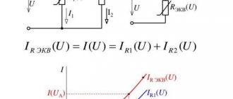
Each load has its own resistance. For example, if one light bulb is connected to the network, then the load resistance is an indicator of this only device in the circuit. If several loads are connected to the circuit, then the resistance is calculated in total for each of them.
The load resistance is calculated in accordance with Ohm's law, that is, Rn = U/I. If several loads are connected to the network, then it will be calculated as follows: first, the resistance of each individual “light bulb” is found. Next, Rn is calculated depending on the type of connection in the circuit: serial or parallel. In parallel, 1/R = 1/R1 + 1/R2 + 1/Rn, where n is the number of connected devices. If the connection is serial, the total R is equal to the sum of all R of the circuit.
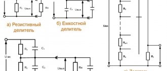
Serial/parallel connections
Summary
- All laws and rules of DC circuits apply to AC circuits, with the exception of power calculations (Joule's Law), provided that all values are expressed and processed in complex form and all voltages and currents are of the same frequency.
- When the vector direction is reversed (which is equivalent to reversing the polarity of the AC voltage source with respect to other voltage sources), this can be expressed in two different ways: by adding 180° to the phase angle or by changing the sign of the amplitude.
- The readings of the measuring device in the alternating current circuit correspond to the amplitudes in the polar form of the calculated values. Algebraic expressions for complex quantities in an alternating current circuit have no direct empirical equivalent, although they are convenient for performing addition and subtraction as required by Kirchhoff's laws for voltages and currents.
Original article:
- Some Examples with AC Circuits
How to find voltage using the formula
People interested in electricity and physics are always concerned with the question of how to find voltages if other characteristics are known. It can be found through many formulas: in accordance with Ohm's law, through the work of current, by adding all the voltages in an electrical circuit and in a practical way - using a voltmeter. How to calculate the indicator using the latter method was described above.
Important! In series-connected circuits, the total voltage is the sum of the values of each load. In a parallel connection, the total voltage is equal to the value of each bulb, which is also equivalent.
Example 1
Two resistors are connected to a 50 V DC voltage source, with an internal resistance of r = 0.5 Ohm. The resistances of resistors R1 = 20 and R2 = 32 Ohms. Determine the current in the circuit and the voltage across the resistors.
Since the resistors are connected in series, the equivalent resistance will be equal to their sum. Knowing it, we will use Ohm's law for a complete circuit to find the current in the circuit.
Now knowing the current in the circuit, you can determine the voltage drop across each resistor.
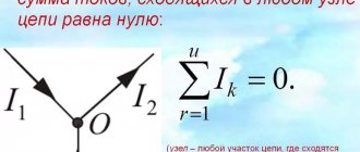
There are several ways to check the correctness of the solution. For example, using Kirchhoff's law, which states that the sum of the emf in the circuit is equal to the sum of the voltages in it.
But using Kirchhoff's law it is convenient to check simple circuits that have one circuit. A more convenient way to check is the power balance.
The circuit must maintain a power balance, that is, the energy given by the sources must be equal to the energy received by the receivers.
The source power is defined as the product of the emf and the current, and the power received by the receiver as the product of the voltage drop and the current.
The advantage of checking the power balance is that you do not need to create complex cumbersome equations based on Kirchhoff's laws; it is enough to know the EMF, voltages and currents in the circuit.
How to find current through resistance and voltage
The current strength is denoted by the Latin [I] or [Y], and it depends on the amount of charge transferred from one pole to the other in a certain period of time, i.e. I = q/t. The current is measured in amperes, and you can find out its value in the circuit using an ammeter.
A man counts the current strength
There are formulas for determining current strength through voltage and resistance. In the first case, the product of current and time is equal to work divided by voltage: I*t = A/U, in the second - according to Ohm’s law, I = U/R. Through power, force will equal P/U.
With a series connection, the current is the same in all parts of the circuit, therefore, equal to the total value in the circuit. Otherwise, the strength of the electric current is equal to the sum of the current strength of all loads.
Thus, there are a huge variety of formulas for finding current, voltage and resistance. They can always be useful for theory, but in practice special devices - an ammeter and a voltmeter - will always help.
Source
Direct current: 2 current sources
Calculation of voltage drops between different points, determination of currents and voltages in a circuit, including using Kirchhoff’s laws - that’s what awaits us in this article.
Problem 1. In the battery shown in the figure, V, Ohm, V‚ Ohm‚ V, Ohm; Om‚ Om. Find the emf and internal resistance of this battery.
To task 1
We simply add up the internal resistances (connected in series):
To find the EMF, note that the sources are turned on “wrongly”, so the EMF will be equal to
Answer: Om, V.
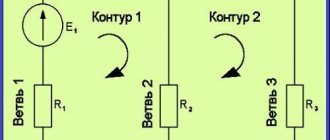
Task 2. Calculate the emf and internal resistance of a battery consisting of three emf sources (Fig.), if the emf of the sources is 10 V, 20 V, 30 V, respectively, and their internal resistances are the same and equal to 1 Ohm. When connecting sources in parallel, they can be converted into one using the following formulas:
To task 2
Then
Now let's recalculate the series connection of two sources:
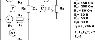
Answer: Ohm, V. Problem 3. In a certain circuit there is a section shown in the figure, Ohm, Ohm‚ Ohm, V, V‚ V. Find the current strength in each resistance and potential.
To problem 3
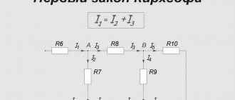
According to Kirchhoff's first law.
Let
Then:
Then the current strength in the branches:
Task 4. Determine the potential difference between the terminals in the circuit shown in the figure, if V, Ohm, Ohm.
To problem 4
The branch resistances are equal
Since the resistances of the branches are equal, the total resistance of both branches
And the current in the unbranched part of the circuit is equal to
This current will be divided exactly in half at a point - again due to the equality of the resistances of the branches. Thus, the currents in the branches are 1 A.
These currents will create voltage drops V, V.
From the figure we can write according to Kirchhoff’s second law:
Answer: B.
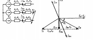
Task 5. Find the potential difference at the terminals of each current source, if Ohm, Ohm, Ohm, V.
To problem 5
Let's determine the current in the circuit; to do this, we first determine the total EMF:
The current in the circuit is:
This current will create a voltage drop of:
On :
Then at the terminals of the first source
At the terminals of the second source
Answer: B, B.
Problem 6. The circuit includes three sources of EMF and two resistors (Fig.) Determine the EMF and internal resistance of the equivalent source acting in the circuit, as well as the potential difference between points A and B, if B, B, V, Ohm, Ohm, Ohm , Ohm, Ohm.
To problem 6
We simply add up all the resistances (connected in series):
To find the EMF, note that the sources are turned on “wrongly”, so the EMF will be equal to
The current in the circuit will be equal to:
This current will create a voltage drop:
According to Kirchhoff’s second law, we write:
Answer: B.
Problem 7. The circuit includes three batteries (Fig. 12.62) V, V, V, Ohm, Ohm, Ohm. Find the voltage at the terminals of the first battery.
To problem 7
We simply add up all the resistances (connected in series):
To find the EMF, note that the sources are turned on “wrongly”, so the EMF will be equal to
The current in the circuit will be equal to:
This current will create a voltage drop:
The required voltage is
Answer: B.