Programmable on/off controller for 3-phase motor
A programmable 3-phase motor controller that automatically turns on/off can be done using a programmable time relay.
In this case, a maximum of eight times the duration can be programmed. The system has two programmable time relays for setting engine start and stop times and two control circuits that are connected to the 3-phase motor starter start and stop switches. The block diagram of the system is shown in Fig. 1. Fig. 1: Block diagram of a programmable 3-phase motor controller.
Let's assume that the same times are set on both time switches. So if a start time of say 8am is programmed for Timer 1 ON mode, then 8.01am will be programmed for Timer 1 OFF mode in the start time switch. And, if a stop time of, say, 9 a.m. is programmed for Timer 2 On Mode, then 9.01 a.m. will be programmed for Timer 2 Off Mode in the Stop Time Switch. When the time reaches 8 am, the start time switch connects the primary winding of transformer X1 to 230 VAC. The output of the power supply is connected to pin 4 of reset IC1. R4 and C3 act as self-starting components. The monostability output at pin 3 goes high for a period equal to 1.1 × R5 × C4, which is almost five seconds.
Browse products for inventors. Link to the store.
New generation three-phase drivers
March 20, 2008
Development directions for the 5th generation of integrated IR drivers for electric drives
Since modern developments of mass electric drives for industrial applications and household appliances are focused mainly on the use of three-phase asynchronous electric motors and contactless DC motors, International Rectifier pays great attention to improving the corresponding element base, including high-voltage MOS gate driver microcircuits. Three-phase driver ICs are the most promising technical solution for controlling drive inverters with power up to several kilowatts. They allow you to integrate the required set of control and protection functions for power electronics on one chip, create the simplest, most compact and stable control circuit, do not require complex power supply circuits, and have high performance. Increasing requirements for mass drive power electronics, primarily in terms of price, compactness, efficiency, and reliability, are also reflected in the requirements for drivers. IR's 5th generation driver technology has been developed specifically to be able to meet these growing demands over the long term. This technology allows for greater integration of functionality while maintaining die area and cost.
In new developments of IR drivers for electric drives with power up to several kilowatts, two main directions can be distinguished.
The first pursues the goal of creating the most compact ICs with the lowest price and limited growth in functionality. These ICs are intended to replace previous generation ICs when upgrading drive electronics, in order to reduce costs and simplify circuit design.
The second is aimed at developing a new generation of drive ICs with significantly higher efficiency, a wide range of functionality while maintaining price levels and circuit complexity.
Within these areas, IR has already started mass production of several new driver families.
Three-phase drivers for modernization of serial products
The first of the new families in this direction is the IRS2336Dx series, which should replace the popular IR2136x series of the previous generation.
General characteristics of the series
The family includes the 600-volt IRS 2336D and IRS 23364D drivers. The output voltage range of the first is 10…20 V (designed to control power MOSFETs), the second is 12…20 V (designed to control IGBTs). The drivers are available in 28-pin DIP, SOIC and 44-pin PLCC lead-free packages. The temperature range for operation of microcircuits is from -40 to 125°C, storage - from -55 to 150°C. Products in this series are classified as industrial ICs according to JEDEC JESD 47-E standard. Microcircuits in surface-mount packages meet the requirements for resistance to humidity level MSL-3 according to JEDEC J-STD-020C. The connection diagram of these microcircuits is shown in Fig. 1.
Rice. 1. Connection diagram for IRS2336xD series ICs
It is in many ways similar to the circuit for the IR2136x series drivers, only the bootstrap ultra-fast diode circuit is missing.
To simplify the transition from old IR2136x series ICs to new ones, the location and assignment of pins has been preserved. The IC has 6 inverter switch control inputs (HIN-upper, LIN-lower), compatible with CMOS and TTL logic of any level (including 3.3 V), which allows for driver control directly from the microcontroller. The inverter switch control outputs (HO-upper, LO-lower) are in phase with the HIN, LIN inputs of the IRS23364D driver and are out of phase with the IRS2336D.
The typical level of output currents of the new series drivers (HO, LO pins of the microcircuit) is 180 mA and 330 mA (gate inflow/outflow current). The graphs from the IRS2336xD series driver reference sheets (Fig. 2) will help you select the driver switching frequency with a known value of the gate charge of the inverter switches and the DC bus voltage.
Rice. 2. Dependence of the maximum driver switching frequency on the transistor gate charge and DC bus voltage
The En (Enable) input is intended for remote control of the driver. Permission to operate the driver is given at a high logical level at the input, prohibition at a low one (level 0.8 V). The IC input filter on this input eliminates the possibility of triggering from spurious pulses up to 200 ns in duration.
Integrated bootstrap loop
In the new drivers, the role of the bootstrap diode is performed by BootFETs - bootstrap MOS transistors integrated into the IC chip, which in many cases eliminates the need to use external bootstrap ultra-fast diodes and resistors. Three bootstrap transistors are connected to the power input Vcc and to the outputs Vв1, Vв2, Vв3 of floating-level power supplies, as shown in Fig. 3.
Rice. 3. Connecting BootFET to IRS2336xD IC
Integrated BootFETs are enabled only when the LO outputs control the lower switches of the inverter are high (Fig. 4).
Rice. 4. BootFET status graph
The voltage Vвs on the capacitor between outputs B and S increases cyclically depending on the time the output LO is at a low level, the capacitance of the capacitor, the source-drain voltage (collector-emitter) and the voltage drop across the antiparallel diode of the inverter. The timing diagrams of booster transistors approximately repeat the state of the LO outputs. BootFETs are in a conducting state when the LO output level is high and when Vвs does not exceed the chip supply voltage Vcc (equal to 15 V) by more than 10%.
Integrated bootstrap transistors can replace external bootstrap diodes in most practical applications. Limitations in their use may be associated either with specific circuit design (for example, when implementing 6-step modulation circuits) or with lower performance than that of ultra-fast diodes (in typical bootstrap circuits, diodes with a reverse recovery time of 100 ns are usually used). In these cases, the problem can be solved by supplementing the switching circuit with a conventional bootstrap circuit with an ultrafast diode.
Increased immunity to interference
In order to ensure high noise immunity, the drivers of the new series retain the separation of signal and power grounds, as was previously done in the IR2136x series. The signal ground output Vss is used in overcurrent protection circuits and control generation at the HIN, LIN inputs. The power ground output COM, together with the LO outputs, is used to form the control of the lower switches of the inverter. In addition, the new drivers use improved input filters. The difference in the operating logic of such a filter is illustrated in Fig. 5.
Rice. 5. Logic of operation of conventional and advanced input filters
An input filter with the usual operating logic blocks the appearance of a high level at the output for the filtering time tFIL,IN, and the duration of the output pulse relative to the input is reduced for the filtering time (dashed line in Fig. 5). In the improved filter, the output signal also appears with a delay tFIL,IN, but the duration of the output pulse coincides with the duration of the input (solid line). This makes it possible to effectively eliminate circuit triggering from both positive and negative impulse noise with a duration of less than tFIL,IN. With longer input pulses, the duration of the input and output pulses coincides with a fairly high accuracy (Fig. 6).
Rice. 6. Pulse duration at the output of the improved input filter
The IRS2336xD series drivers feature advanced input filters on the HIN, LIN inverter control inputs (350 ns filter time) and EN input (200 ns).
Ensuring reliable control of inverter keys
The time delays between the control signals at the input and the output signals vary in the range of 400...750 ns, and the rise and fall times at the output - in the ranges of 110...190 ns and 35...75 ns, respectively. Three-phase drivers provide several stages of functional protection to prevent the simultaneous switching on of the inverter transistors and the occurrence of through currents.
A special logic circuit sets a low level at the gate control outputs of the upper and lower switches while a high logical level appears at the control inputs, thereby blocking the operation of the driver.
In the dynamic operating mode of the driver, the spread in the delay times between the input and output signals and the edges of the output signals of the driver channels can lead to overlapping of the output signals and unwanted operation of the inverter switches. To prevent this, a logical node is provided in the driver circuit, which ensures the same response time of the upper and lower driver channels that control the inverter rack. The maximum response time difference is 50 ns (data sheet parameter MT). In addition, the difference in response times between both lower and upper keys is eliminated.
To prevent through inverter currents, the drivers are equipped with a unit for generating a fixed pause for switching. Nominal pause duration 300 ns (range 190...420 ns). The pause generation circuit provides a pause duration spread of no more than 60 ns for the upper and lower key control channels. The same applies to the spread of pause durations between the control circuits of all three inverter racks.
High tolerance to negative output offset
The voltage at the outputs of a three-phase inverter (midpoints of the racks) under ideal operating conditions varies from zero (zero potential bus) to the DC bus voltage. At the midpoint of the Vs post, a significant negative bias can occur in a short time and be transferred to the driver output. The reason for this may be the presence of an inductive load, parasitic inductances in the inverter racks, or switching large currents for short periods of time. This situation can occur both in operating mode and in short circuit mode, shutdown due to overcurrent, etc. The new series of drivers are able to successfully withstand such influences. Graph in Fig. 7 illustrates the ability of the IRS2336xD series drivers to operate at shock negative voltage offsets down to minus 60 V.
Rice. 7. Resistance to negative offset at the output (midpoint of the rack) as a function of time
With this in mind, the new series drivers are much more reliable power ICs for controlling drive inverters in real-world operating conditions.
Protection functions
The new ICs retain the protection functions previously implemented in the IR2136x series ICs.
The FAULT pin is intended to transmit information about an emergency situation during the operation of the timer, programmed by the external circuit RRCIN, CRCIN. The resistor value can be selected in the range from 0.5 to 2 MΩ, the ceramic capacitor can have a capacitance of up to 1 nF. The driver's operation is blocked in two cases - when the supply voltage is low (level 8.9...8.2 V) and when there is a high level at the ITRIP input.
Figure 8 illustrates the second of these situations. When the ITRIP pin is high, the voltage at the VRCIN and VFAULT pins is reduced to the level at the Vss pin (signal ground).
Rice. 8. Timing diagrams of the timer and FAULT output
When the signal level at the ITRIP pin becomes low, a timer is started, which, after a time tFLTCLR (determined by the time constant of the RC circuit), resets the FAULT input, the signal level at which becomes high again.
The ITRIP input can be used to detect overcurrent on the inverter's zero potential bus. In this case, the IC outputs are switched to a low level and an emergency signal is issued via the FAULT output. The ratings of the divider R0, R1, R2 (Fig. 9) are determined based on the threshold level of 0.46 V at the ITRIP input and the level of the protection operation current.
Rice. 9. Overcurrent detection circuit
Overheating protection can be provided in a similar manner. The parameters of the thermistor Rt and resistors R3, R4 must be selected so that the threshold voltage of 0.46 V is achieved at the maximum permissible temperature. Figure 9 shows how to achieve these capabilities simultaneously using decoupling diodes.
(To be continued)
Literature
1. Data sheet IR2136x
2. Data sheet IRS2336xD.
Obtaining technical information, ordering samples, delivery - e-mail
Power miniblock for high-current POL converters
International Rectifier has announced the iP1206 , a new technical solution for the implementation of step-down synchronous converters used to power telecommunications and network equipment. The chip is the latest addition to the iPOWIRTM of power miniblocks, containing all the passive components and semiconductor devices for implementing the power part of synchronous converters. Based on the iP1206, you can implement a single-phase converter with an output current of up to 30 A and a two-phase converter with two independent outputs for currents of 15 A. Both options are based on antiphase operation of the channels in order to reduce ripple of the input voltage and current. To achieve high volumetric density, the iP1206 uses a full-fledged PWM controller and an optimized power stage based on modern semiconductor devices.
Since the new chip contains all the semiconductor and passive components that are important in terms of conversion quality, only a few additional passive power components are required to create a high-quality converter. At the same time, the requirements for the qualifications of the developer and the printed circuit board are significantly reduced. Features of the iP1206PBF are a constant PWM frequency of 600 kHz in channels, lossless current limiting, overvoltage and overheating protection, offset start mode, and output voltage tracking.
The input voltage range is 7.5...14.5 V, output voltage 0.8...5.5 V. The microcircuit is produced in an LGA package. To simplify the development of the use of iP1206, the company offers a demonstration converter IRDCiP1206-B 2x15A and online simulation of the operation of the iP1206 Spice circuit simulation.
•••
Our information channels
DIY three-phase motor controller
Delta printers are extremely demanding on the precision of manufacturing components (frame geometry, length of diagonals, backlash in the connection of diagonals, effector and carriages) and the entire geometry of the printer. Also, if the limit switches (EndStop) are located at different heights (or different actuation moments in the case of contact limit switches), then the height along each of the axes turns out to be different and we get an inclined plane that does not coincide with the plane of the working table (glass). These inaccuracies can be corrected either mechanically (by adjusting the height limit switches) or software. We use a software calibration method. Next we will look at the basic settings of the delta printer. To control and configure the printer we use the Pronterface
. Printer calibration is divided into three stages:
Stage 1. Adjusting the plane using three points
Alignment of three points in one plane - A, B, C (located next to three guides). Essentially, it is necessary to clarify the height from the plane to the limit switches for each of the axes. Most (if not all) boards for controlling a three-dimensional printer (In our case, RAMPS 1.4) operate in a Cartesian coordinate system, in other words, there is a drive on the axis: X, Y, Z.
In a delta printer, you need to switch from Cartesian coordinates to polar ones. Therefore, we agree that those connected to the motors X, Y, Z
corresponds to axes
A, B, C.
(Counterclockwise starting from any engine, in our case looking at the logo on the left - XA, on the right YB, far ZC) Further, when slicing, printing and controlling the printer in manual mode, we will operate the classical Cartesian coordinate system, the printer electronics itself will recalculate the data into the system it needs.
We need this convention to understand the operating principle and direct calibration of the printer. The points by which we will calibrate will be called similarly (A, B, C) and the position of these points is A= X-52 Y-30
;
B= X+52 Y-30
;
C= X0 Y60
.
Diagram of a 3-phase motor with a programmable controller
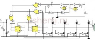
Rice. 2: Schematic diagram of a programmable 3-phase motor controller. Since pin 3 of IC1 is high, relay RL1 is energized for five seconds, which in turn closes the start switch, extending the three-phase power to the motor. This is almost the same as physically pressing the start switch of a 3-phase motor starter for five seconds. When the time reaches 9 am, the second time switch (stop switch) supplies 230 VAC to the primary winding of transformer X2. Again, through the use of a full wave rectifier and filter circuit, 12 VDC is supplied to a second monostable circuit having relay RL2. The normally closed (N/C) terminal of the relay is connected in series with the 3-phase motor starter switch. So, the relay breaks the circuit to stop the engine. This is an example of one time duration from 8am to 9am. Thus, a maximum of eight time intervals can be programmed to switch a three-phase motor on and off. It is possible to configure the days of the week for the controller to operate. For example, it can operate from Monday to Friday, Monday to Saturday, all seven days of the week, or only on a specific day of the week. This system can have many uses, including running a water pump in a multi-story commercial building to fill the overhead tanks only for five or six days a week. It can also be useful for farmers, industrial plants or railway stations where 3-phase motors are used. DIY electronics in a Chinese store.
Scheme of work
Two identical power supply circuits are built around transformers X1 and X2 with associated components, as shown in Fig. 2. The device provides 12 VDC to two control circuits built around two 555 timers IC1 and IC2, which are configured in monostable mode. The two timers used in this system are manufactured by Frontier, model TM-619-2. They operate on 230 V AC at 50 Hz. Each switch has a built-in single changeover relay with a rated resistance of 16A. Has LCD display with buttons such as CLOCK, TIMER, DAY, HOUR, MIN and MANUAL as shown in fig. 3. These buttons are used to set the real time clock and program various time intervals. A time relay is a programmable digital device that has a digital real-time clock and can be programmed for a maximum of eight time intervals. The duration can be for a specific day, alternative days, Monday to Friday, Monday to Saturday or Monday to Sunday.
Rice. 3: Front part of the time relay.
Rice. 4: Rear part of the time relay.
Rice. 5: Typical 3-phase motor starter.
By holding down the clock button, real time is set using the HOUR, MIN and DAY buttons, and various durations are programmed using the TIMER, HOUR, MIN and DAY buttons.
There are three modes namely ON, AUTO and OFF written just below the display. After the programming time has expired, the black horizontal line segment is saved in AUTO mode from OFF mode by pressing the MANUAL button. The timing relay provides five external pins, numbered 1 through 5, as shown in Fig. 4. Pins 1 and 2 of the CON1 and CON2 connectors for the start and stop switches are supplied with 230 VAC, with pin 1 being neutral.
Current-carrying contacts 2 are connected by a wire to contacts 3, and the output voltage is removed from contacts 1 and 5. There is a button cell position. CR2032 for storing clocks and programmed times. This means that even if the 230 VAC is disconnected, the clock and programmed time are not disturbed (if there is a power failure) for 60–90 days. When mains power is available, the element charges continuously. The control circuit has two monostable multivibrators with a time delay of five seconds.
Start time switch 1 is connected to the first monostable multivibrator built around IC1, as shown in Figure 2. The real time clock of time switch 1 is set by pressing and holding the CLOCK button and adjusting the time using the HOUR, MIN and DAY buttons. If in weekly mode the duration needs to be programmed for the first time from 8:00 to 9:00, then mode 1 ON is programmed at 8:00, and mode 1 OFF is programmed for the first time at 8:01.
The motor is turned off using a second multivibrator circuit, as shown in Fig. 2, in which the N/C and common terminals of relay RL2 are connected in series with the starter switch. The real time clock is set by pressing and holding the CLOCK button and adjusting the time using the HOUR, MIN and DAY buttons. The switch-off time, that is, 9 am, is programmed in mode 1 On. With weekly day selection by pressing the TIMER button. Pressing the TIMER button again sets 9.01 AM to 1 OFF mode with weekly day selection in the second timer. When the time 9 AM is reached, the second timing switch supplies 230 VAC through the primary winding of step-down transformer X2, and the second full-wave rectifier supplies 12 VDC. This voltage is applied to the second monostable multivibrator circuit, as shown in Fig. 2.
Rice. Figure 5 shows a photograph of a typical three-phase motor starter along with the internal starter assembly. Shown to the right of the photo are two buttons; the green button is used to start the engine and the red button is used to stop it. It also has a relay coil. When the start switch is briefly pressed, current flows through the coil, the relay strip is pulled towards the coil iron, and three-phase voltage is applied to the motor.
Rice. 6: Three-phase motor controller printed circuit board.
Rice. 7: PCB component diagram.
Download PDFs for PCBs and Components: Click Here
One chip - one motor. STSPIN32F0 - a ready-made solution for controlling BLDC motors
STMicroelectronics is a world leader in the production of microcontrollers. Over the past ten years, the company has revolutionized and created the most powerful ecosystem based on the budget STM8 and STM32 families. STMicroelectronics also boasts interesting developments in the field of electric motor control. Sometimes the company experiments and releases innovative specialized products to the market. A striking example of this is the STSPIN32F0 chip, which combines an ARM Cortex-M0 core microcontroller and an electric motor control system.
How to buy a three-phase meter
You can buy a three-phase electricity meter either separately or as part of a kit with a controller for remote transmission of readings. The second option is more profitable, since the price of the kit includes a discount. However, each system component can be purchased separately. Delivery is carried out throughout Moscow and throughout Russia. For installation, connection and configuration, please contact our partners.
If you need help selecting equipment, please contact our consultants by phone or online chat.
Source
Speed controllers for asynchronous single-phase motors 220 V
For a single-phase control system, all such speed controllers require a tachogenerator built into the engine. The controller compares the current value of the motor shaft rotation speed, determined using a tachogenerator, and the required speed value, set by a potentiometer or an external analog signal, and depending on this, regulates the speed using the supply voltage. This scheme is very reliable; single-phase speed controllers are widely used in a wide variety of equipment. All proposed control units are suitable only for electric motors and gearmotors of the series (adjustable single-phase motors with a built-in tachogenerator) and YF (motor with a built-in brake and tachogenerator), for the YS series (the same gearmotors without a tachogenerator) the controllers are not suitable for both and for all versions of motors with three-phase power supply (with or without brake).
To control three-phase motors and geared motors, we recommend considering the T13 series of frequency converters with single-phase input and three-phase output.
