Stepper motor driver circuit
The stepper motor driver circuit does not contain expensive parts or programmable controllers. Operation can be adjusted over a wide range using potentiometer PR1. There is a change in the direction of rotation of the engine. The stepper motor coils are switched using four MOSFETs T1-T4. The use of high-power transistors of the BUZ10 type in the block will allow you to connect motors even with very high current.
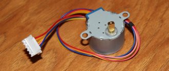
What is a stepper motor?
A stepper motor is an electrical machine designed to convert electrical energy from the network into mechanical energy. Structurally, it consists of stator windings and a soft magnetic or hard magnetic rotor. A distinctive feature of a stepper motor is discrete rotation, in which a given number of pulses corresponds to a certain number of steps taken. Such devices are most widely used in CNC machines, robotics, and information storage and reading devices.
Unlike other types of machines, a stepper motor does not rotate continuously, but in steps, which is where the name of the device comes from. Each such step is only a fraction of its full revolution. The number of steps required to completely rotate the shaft will vary depending on the connection diagram, motor brand and control method.
Advantages and disadvantages of a stepper motor
The advantages of using a stepper motor include:
- In stepper motors, the angle of rotation corresponds to the number of electrical signals supplied, while after stopping the rotation, the full torque and fixation are maintained;
- Precise positioning – provides 3 – 5% of the set step, which does not accumulate from step to step;
- Provides high speed start, reverse, stop;
- It is highly reliable due to the absence of rubbing components for current collection, unlike commutator motors;
- The stepper motor does not require feedback to position;
- Can produce low speeds for a directly applied load without any gearboxes;
- Relatively lower cost compared to the same servos;
- A wide range of shaft speed control is provided by changing the frequency of electrical pulses.
Circuit Features and Details
- four phase stepper motor control
- smooth adjustment of rotation speed within the entire range
- changing the direction of rotation of the motor
- possible engine stop
- 12V DC power supply
Parts – IC1: 4070, IC2: 4093, IC3: 4027, T1-T4: BUZ10, BUZ11
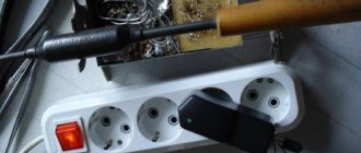
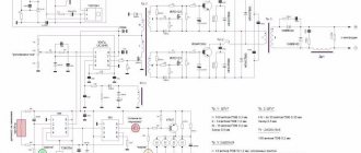
The stepper motor driver unit is assembled on the printed circuit board shown in the figure. We install, as a rule, starting with soldering resistors and sockets for integrated circuits, and finally electrolytic capacitors and high-power transistors.
The unit, assembled from proven components, does not require configuration and starts immediately after power is applied. With the values of the elements indicated in the diagram, it allows a 5.25” engine to operate and changes the rotation speed in the range of 40 rpm. up to 5 rpm
Useful: Circuit diagram of an audio amplifier with a preamplifier, power supply and speaker protection relay
Stepper motor control
As already noted, there are several ways to control a stepper unit. Each of the options has a number of features regarding the supply of signals to the existing poles.
The main management methods include:
- Wave. The peculiarity is the supply of excitation to one winding. It is to this that the rotor poles are pulled. At the same time, the motor is not able to withstand a large load, because it produces only part of the torque.
- Full step. The essence of such control is the simultaneous excitation of two phases, which guarantees the highest torque in a parallel connection circuit. If you connect the windings in series, maximum current and voltage will be created.
- Half-step. A combination of the two modes discussed above. When implementing such a circuit, voltage is alternately supplied to the stepper motor. First it is sent to one coil, and then to both at once. As a result, the best fixation is guaranteed at the highest speeds and the maximum number of steps.
To overcome inertia and achieve softer control, a micro-stepping structure is used. A special feature is the setting of a sinusoid using numerous pulses.
As a result, the interaction forces between the magnetic circuits change more smoothly, and smooth movement between the poles is ensured. As a result, jerking during operation is reduced.
Based on the presence of a controller, stepper motors are divided into two types:
- Controllerless. An H-bridge circuit is used with the ability to change polarity to reverse the device. Depending on the situation, it is done on a microcircuit or transistor principle. First, voltage is applied to the bridge, and, thanks to switches placed in parallel, current flows through the motor windings. As a result, it is possible to establish rotation in any direction.
- Controller. The advantage of the design is the ability to control the stepper unit in different modes. The key element is the electronic unit, which produces a group of signals and sets the sequence of their transmission. To avoid damage during a short circuit or other accident on the motor, each terminal is protected with a diode that does not allow a pulse to pass in the opposite direction.
The most popular include two control schemes - from a controller with a differential input and an “open collector” output.
The first option features reliable protection against interference by connecting the direct/inverse signal to suitable poles. Here it is necessary to shield the wire through which the signal is supplied. This is the optimal solution for low-power devices.
The second circuit is distinguished by the connection of the “positive” outputs of the controller connected to the “positive” terminal. When voltages above 9V are applied, a resistance must be added to reduce the current. In addition, using this solution you can set the required number of steps in a certain speed mode and set acceleration.
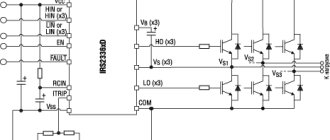
Bipolar Stepper Motor Controller
The circuit represents a low-cost and, above all, easy-to-assemble alternative to available microprocessor-based bipolar stepper motor controllers. Recommended where control accuracy plays a lesser role than price and reliability.
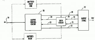
The circuit diagram can be divided into the following blocks:
- serial chip generating bit strings,
- local clock generator,
- coil power control circuit,
- H-bridge output buffers,
- protection circuits for input control signals.
The controller must be powered by a constant voltage, well filtered, preferably stabilized.
Now a few words about the H-bridges that will work with this driver. They must accept all possible logic states (00, 01, 10, 11) at their inputs without risk of any damage. It’s just that in some configurations of bridges built from discrete elements, simultaneous activation of two inputs is prohibited - they naturally cannot be used with this controller. Bridges made in the form of integrated circuits (for example L293, L298) are resistant to this.
And finally, the third version of the controller, based on STK672-440 microcircuits, has all the necessary protections and functions, see the link.
Stepper Motor Controller
Stepper motor controller In amateur radio literature, many descriptions of stepper motor control devices have been published; this stepper motor controller has a number of differences and advantages. The proposed bipolar stepper motor controller is built from a small number of readily available cheap parts, has low current consumption and can be adapted for use in various devices.
The use of bipolar power supply for output electronic switches made it possible to halve their number and obtain an engine stop mode in which no current flows through its windings. The control program provides a fixed duration of operating pulses at any step frequency, which saved the key transistors from excessive heating. The use of optocouplers to control keys provides power isolation, the ability to independently power the control unit and keys that switch the motor windings.
The stepper motor controller circuit is shown in the figure. The control unit is built on a DD1 microcontroller (PIC16F84A-04/P). The purpose of the control buttons is as follows: SB1 - clockwise rotation; SB2 - counterclockwise rotation; SB3 - increase in step frequency; SB4 - decrease in step frequency; SB5 - stop. The supply voltage values of the stepper motor +11shd and -11shd depend on its type, but should not exceed 27 V in absolute value - half of the collector-emitter voltage permissible for phototransistors of the optocouplers used. A drawing of a printed circuit board for a stepper motor controller and the placement of parts on it are shown in the figure, the dimensions of the board are 76×53.
For the microcontroller, a panel is installed on the board into which it is inserted already programmed. The source text of the microcontroller program contains all the necessary comments, and if necessary, it can be changed, for example, introducing a half-step motor control mode or, using free ports of the microcontroller, adding limit switches to limit the rotation sector, or setting the required number of steps. It is worth noting that the necessary order of opening transistors VT1-VT4 is implemented in the program taking into account the PCB layout.
A correctly assembled stepper motor controller does not require adjustment. In it, as VT1-VT4, you can use any complementary pairs of medium-power transistors, for example, the KT814 and KT815, KT816 and KT817, KT972 and KT973 series or similar imported ones. Suitable transistor optocouplers can be found in any switching power supply where they are widely used. We get the firmware and printed circuit board here
Stepper Motor Driver
It is impossible to control a stepper motor without using a driver - an electronic device that ensures its operation taking into account control signals.
In other words, this is a circuit element designed to control the motor windings by supplying digital signals.
Thanks to this design, rotation of the motor rotor is ensured. The driver works after connecting the power source, the windings of the device itself and the control signal source.
Depending on the type of driver, a number of additional tasks can be solved:
- control of overcurrent, voltage increase and polarity reversal;
- automatic reduction of current in case of prolonged inactivity;
- protection against back EMF effect;
- construction of simple movement patterns without using a computer (built-in frequency generator), etc.
Structurally, the driver consists of a controller and a power part. The first component is based on a microprocessor and can be programmed, and the second is a semiconductor power amplifier, the purpose of which is to convert the current pulses supplied to the phases.
Drivers are divided into three categories (according to the type of current delivery):
- Constant voltage. It supplies high potential to each winding in turn. The total current depends on the resistance of the latter, and at high speeds - on the inductance. Such drivers have low efficiency and can only be used at low speeds.
- Two-level. First, voltage is applied, due to which the current in the winding rises to the required value, after which the potential source is turned off, and the current is maintained by a low voltage source. Such drivers have higher efficiency and reduce motor heating. They work in full and half step mode.
- PWM type. They are in greatest demand due to their reliability and ease of use. Their feature is that a high voltage PWM signal is supplied to the winding, cut off by a small current. Such drivers are distinguished by their intelligence and programmability.
Additionally, stepper motor drivers vary in type. They come in analog, digital and encoder versions. Let's talk about them in more detail.
Analog
They are characterized by high reliability and efficiency due to relatively low current consumption.
The task of such devices is to alternately supply a pulse to different stator windings, taking into account a predetermined program. This ensures a certain angle and direction of rotation.
Pros of analog drivers:
- low price;
- short circuit and high voltage protection;
- automatic current reduction;
- no risk of accidental overheating.
The main models include:
- CW-230. Designed to control a bipolar stepper unit for two phases with a maximum current of up to 3 A. The motor can be controlled in a mode of up to 1/64 steps. The power unit is controlled using three signals supplied to the differential inputs. Pros: low price, isolation of input signals, protection against erroneous connection, short circuit and high voltage.
- QJ Designed to control a bipolar stepper motor with two phases and a maximum current of up to 4.5 A. Control is available in modes up to 1/256 steps. For control, three signals are used, which are supplied to the inputs PUL, DIF and ENA. Thanks to this feature, you can connect to the LPT port of a PC and successfully work with the CNC machine program. Pros: full set of protections, automatic current reduction, isolated input signals, affordable price.
- QJ6060AC - designed to control a 2-phase stepper motor. The highest current parameter is up to 6 Amperes for each phase. Control available in 1/128 steps. Three signals are used for control (as in the model discussed above). SD connection is available for CNC machines and a number of plotters.
Digital
These are more modern models that operate on the basis of a digital control signal. It is based on a 32-bit processor, which improves the performance of the equipment used.
Motors working with such a driver produce low vibration levels, minimal heating, and low noise levels.
Advantages of digital devices:
- automatic setup;
- high performance;
- overload protection;
- larger set of functions;
- maximum division by steps;
- automatic voltage reduction at XX, etc.
Popular models:
- 2DM542 is a 2-phase device based on a 32-bit processor. Featuring a familiar way of changing current, it guarantees a high level of performance, optimal torque, increased acceleration and stability. Thanks to improved algorithms, stability to load changes, optimal acceleration and the required torque are guaranteed.
- 2DM Like the model discussed above, this digital driver has a 2-phase design and is built on a 32-bit CPU. Its use makes it possible to achieve smoother operation of the motor, improve its performance and torque, achieve optimal acceleration and stability to load changes. The model has built-in devices for self-testing and auto-tuning.
- Leadshine DM-805-AI. The peculiarity of the driver is a high degree of smoothness of the system, guaranteeing optimal torque and stability of the device. Thanks to the built-in self-testing and automatic configuration technology, the driver effectively interacts with different types of motors. At the same time, the engine itself runs smoother, overheats less and makes almost no noise. For convenience, several operating modes are supported, there are three built-in potentiometers that allow you to set acceleration, speed and braking parameters. The driver is used for NEMA-17-34 units of various modifications.
With encoder
Such drivers are devices built on a digital principle and have a high response rate. Used as a replacement for more complex control systems requiring high precision.
Features include:
- availability of feedback;
- torque and rotation speed support;
- guaranteeing smooth movement and low noise levels;
- protection against current and other overloads;
- reducing engine heating and ensuring its normal operation.
When using such a driver, you can not be afraid of delays while maintaining maximum performance.
Popular models include:
- 2HSS86H is a 2-phase digital servo driver that combines the functions of a stepper and a servo drive. Suitable for equipment requiring high torque, speed, profitability and stability at 0 speed. Its use guarantees smoothness and minimal noise of the stepper motor.
- CWDS860H is a new generation device that combines the best qualities of servo and stepper devices. Guarantees reduced vibration, reduced noise and greater positioning accuracy. The uniformity of operation and high response speed make this model suitable for programs that need to move quickly over short distances and require smooth operation. Features of the model: stability at 0 speed, speed and profitability.
- HBS57 is an alternative option for programs that require high performance and increased reliability (where a servo drive is used). The system includes a 3-phase stepper and a digital high-speed driver. The device is characterized by a high response speed and the absence of roars. The engine heats up less, has less noise and runs without delay.
DRIVER 2HSS86H
In addition to those discussed above, there are other types of drivers, but they are used less frequently.