Asynchronous single-phase electric motor
If one of the three supply wires of a rotating three-phase asynchronous electric motor is interrupted, then with a light load it will continue to operate on one phase. A rotating field remains in the engine. However, when switched on single-phase at rest, such a motor will not work even without load. If the third phase of the winding is connected through a capacitor to one of the two supply wires, then a three-phase motor connected to a single-phase current network will begin to work and its performance characteristics will be similar to those of a conventional three-phase asynchronous motor.
Asynchronous motor: what is it
An asynchronous motor is an asynchronous electrical machine used to convert electrical energy into mechanical energy. Asynchronous literally means non-simultaneous - here it means that in an asynchronous motor the magnetic field always has a higher rotation speed than the rotor, which seems to be trying to catch up with it. These machines operate on alternating current networks.
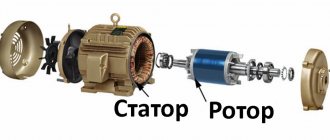
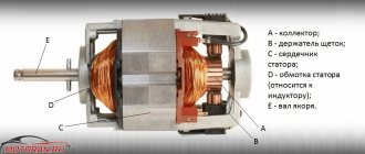
Any asynchronous motor consists of two key components: the rotor and the stator. These parts do not contact each other and are separated from each other by an air gap in which a moving magnetic field is formed.
The stator of an asynchronous machine consists of the following parts:
- Frame. Serves to hold all engine parts together. For small engines, as a rule, one-piece cast casings made of cast iron, steel and aluminum alloys are used.
- Core or magnetic conductor. It is assembled from plates, for the manufacture of which special electric steel is used. It is pressed into the housing and improves the magnetic induction properties of the machine. Each core plate is coated with a special varnish to reduce losses when eddy currents occur. In some cases, the design of an asynchronous motor requires the installation of a core housing that combines both functions.
- Windings Installed in the grooves of the core. It consists of three coils of copper wire sections located at an angle of 120˚ relative to each other. It is called primary because it connects directly to the network.
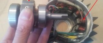
The rotor design consists of a main block with a ventilation impeller, supported by bearings. The connection of the rotor with the driven mechanism is ensured using direct connection, gearboxes or other methods of transmitting mechanical energy. Asynchronous motors use two types of rotors:
- The massive rotor is a single circuit made of a durable ferromagnetic compound. Currents are induced inside it, and it also plays the role of a magnetic circuit in the structure.
- A squirrel-cage rotor (invented by the great Russian engineer Mikhail Osipovich Dolivo-Dobrovolsky, like all three-phase current) is a system of conductors connected by rings, similar in appearance to a squirrel wheel. Currents are induced inside it, whose electromagnetic field interacts with the magnetic field of the stator, causing the rotor to move.
squirrel wheel
We recommend watching this video. Although it is old, it is interesting and educational. It will allow you to close unclear points.
Two-phase electric motors and their features
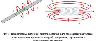
Two-phase asynchronous brushless and commutator electric motors are used to connect to a three-phase AC network via two wires. In addition to the winding, which is directly connected to the network, two-phase motors also have a second winding. It is connected in series with either a capacitor or a coil - with one of the phase-shifting devices of the electric motor. Two-phase windings that are perpendicular to each other can create rotating magnetic fields. To do this, the winding phases must be powered with currents that are 90 degrees out of phase. In this case we have a rotating magnetic field, as in a three-phase motor.
Advantages and disadvantages of two-phase electric motors
In a two-phase electric motor, by analogy with a three-phase one, the rotor of the motor itself receives acceleration until it reaches the final rotation speed. The torque of a two-phase electric motor is caused by currents that are caused by the rotating magnetic field of the rotor bars. In this case, the final rotation speed of the rotor is lower than the rotation frequency of the magnetic field.
- If the phases of the motor winding are powered from only one phase of the electrical network with a single-phase current, capacitors are used to produce a rotating magnetic field. This engine has its drawbacks. This is a ripple current, which in turn reduces torque. To compensate for this drawback, the installation is complicated by disconnecting part of the tank.
- Two-phase electric motors can be made not only with a squirrel-cage rotor, but also with a hollow rotor. In this case, the rotor is made in the form of an aluminum cylinder, which rotates in the air gap between the inner and outer stator. In an aluminum cylinder, the rotating field causes eddy currents. In the air gap between the stators they interact with the magnetic field, and thereby create the rotating torque of the electric motor. The final asynchronous rotation speed of the cylinder corresponds to the load on the shaft.
- The favorable performance characteristics of the electric motor are due to the low moment of inertia of the hollow rotor. Such electric motors are designed primarily for low power.
Areas of application of two-phase electric motors
The main area of application of two-phase motors is automatic devices. For example, electric motors with a hollow rotor are often used for automatic control in bridge and compensation circuits.
Also, two-phase electric motors are used as controlled motors, regulating the rotation speed, torque, changing the voltage phases of the windings. You can buy high-quality electric motors from our company.
Date: Saturday, 18 January 2014
Connection diagrams
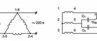
In order to connect a three-phase asynchronous motor, several different circuits are used, but the most commonly used are delta and star.
Triangle
The advantage of this scheme is that when connected according to it, a three-phase motor can develop the highest rated power. To do this, the windings are connected according to the end-to-beginning principle, which in the schematic diagram looks like a triangle, but in the form of a triangle it is not always convenient to understand what’s what. Therefore, we offer for analysis the diagram below, and then the photograph already assembled (even lower).
triangle connection diagram
In three-phase electrical networks, the linear voltage between the terminals of the windings is 380 V. In this case, there is no need to create a working zero. It is important to note that in such a circuit a large inrush current can occur, significantly overloading the wiring.
Star
This connection method is the most used in networks with three-phase current 380 V. The name of the circuit is due to the fact that the ends of the windings are connected at one point, like star rays. The beginnings of the windings are connected via switching equipment to the phase conductors. In such a linear design, the voltage between the beginnings is 380 V, and between the junction and the connection of the conductor - 200 V. Below is a diagram, and even lower is a photograph in assembled form.
star connection diagram
A three-phase motor for 380 V networks connected in this way is not able to develop maximum power due to the fact that the voltage on each winding is 220 V. In turn, this circuit prevents the occurrence of overcurrents, which ensures a smooth start.
The possibility of connecting the motor in one way or another is usually indicated on its plate. The Y symbol means "star" and the ∆ symbol means "triangle". You can determine the circuit on an already connected machine by the type of windings - one double jumper between them indicates that a “star” is used (first photo from the bottom), and if three jumpers are visible between the terminals of the windings - a “triangle” (first photo from the top).
Asynchronous motor, triangle assembly.
Asynchronous motor, star assembly
In the case when it is necessary to start a three-phase asynchronous electric motor in the opposite direction of rotation, the two supply wires from the three-phase source should be swapped.
Functional and operational features
Characteristic advantages of asynchronous motors:
- Their design does not contain collector groups, which increase wear on other types of engines due to additional friction.
- Power supply of asynchronous electrical machines does not require the use of converters and can be provided by an industrial three-phase network.
- Due to fewer parts and structural elements, they are relatively easy to maintain and have a long service life.
Among the disadvantages are:
- The scope of application of asynchronous motors is somewhat limited due to the low starting torque.
- The high reactive power they consume during operation does not affect the mechanical power.
- The large inrush currents consumed when starting these motors may exceed the allowable values of some systems.
Two Phase AC Motor
Area of use: low power asynchronous and synchronous motors. The essence of the invention: the magnetic circuit of the motor stator consists of an open annular yoke, an annular magnetic cage and three poles laminated from plates, the planes of which are parallel to the radial plane passing through the axis of this pole and the axis of the motor, the yoke and magnetic cage are laminated in the usual way from sheets, the planes of which perpendicular to the axis of the machine, the poles are installed in grooves made on the outer surface of the cylindrical cage, two poles are located diametrically opposite to each other, and the third pole is located in the middle between them, a slot is made in the cage diametrically to the middle pole, four protrusions are made on the outer surface of the cage, the radial axes of which located at angles of 45o to the axes of the poles, the annular open yoke is pressed onto the protrusions of the cage and poles, one phase of the winding includes two coils located on both sides of the middle pole, and the other consists of two half-phases, each of which includes two coils located on either side of each of the other two poles. Technical result: reduced consumption of active materials, increased manufacturability and reduced labor intensity, improved performance characteristics. 1 ill.
The invention relates to electrical engineering and can be used in the production of low-power asynchronous and synchronous motors designed to be powered from a single-phase network. Such motors are usually two-phase in their internal structure, with one phase connected directly to the network, and the other through a phase-shifting element (most often a capacitor). Typically, the stator winding is distributed over its slots, and it is placed in the slots either manually, which is a very labor-intensive operation, or using expensive, complex and unreliable machines that require constant maintenance and adjustment.
To reduce the labor intensity of manufacturing and increase the manufacturability of low-power motors, they are made with concentrated windings on the stator, for example, asynchronous motors of the DKV series [1]. The prototype of the proposed invention is a two-phase capacitor motor designed to be powered from a single-phase network, [2] p. 15, fig. 1.3, b. In this engine, the stator is detachable. The pole system consists of four pronounced poles, the opposite pairs of which belong to one of the phases; the pole pieces of all four poles are identical and are connected to each other by jumpers, resulting in the formation of a single cross of poles, which is pressed into the stator yoke. The stator winding coils are wound separately on special frames, put on the poles before pressing the latter into the stator yoke. Despite the four pronounced poles in the stator magnetic system, each of its phases creates a two-pole magnetic field. The coil of each phase occupies two opposite poles, and the zone of action of the magnetic field of the phase extends only half the circumference of the rotor. This leads to the main disadvantages of these motors: poor use of the main (two-pole) spatial harmonics of the field (the phases act “next to” each other, their areas of action do not overlap each other, as in machines with windings distributed over slots). In addition, the field induction curve of each phase is close to rectangular, and the width of the rectangle is equal to half the half-cycle of the curve; in the second half of the half-cycle, the induction of a given phase has a zero value (the field of another phase is located there). Such a rectangular curve has the same high specific content of higher spatial harmonics as a rectangular curve without zero flanges, when the width of the rectangle is equal to the entire pole division. The proposed electric motor achieves a reduction in the consumption of active materials, an increase in manufacturability and a reduction in the labor intensity of manufacturing the engine, as well as the ability to regulate the shape of the magnetic field distribution curve in the machine gap due to the choice of design relationships in the stator magnetic circuit, as a result of which the performance characteristics of the motor can be improved. A two-phase AC motor is proposed, containing a split stator with salient poles and a two-phase winding consisting of inserted coils, wound and separately insulated, in which the stator contains three poles laminated from plates, the planes of which are parallel to the radial plane passing through the axis of this pole and the axis of the motor, the poles are installed in grooves made on the outer surface of a cylindrical cage laminated from plates perpendicular to the pole plates, two the poles are located diametrically opposite to each other, the third is located in the middle between them, a slot is made in the cage diametrically opposite to the middle pole, preventing the flow from closing past the rotor, on the outer surface of the cage there are four protrusions, the radial axes of which are located at angles of 45o to the axes of the poles, on the protrusions and a ring yoke is pressed onto the poles, open between two protrusions of the yoke, located on both sides of the slot in it, and the coils of the two-phase winding are located on the yoke, with one of the phases consisting of two coils located on either side of the middle pole, and the other of two half-phases , each of which includes two coils located on either side of each of the other two poles. The drawing shows a cross section of the proposed electric motor. The stator magnetic circuit consists of an open annular yoke 1, an annular magnetic cage 2 and three poles 3, 4, 5, laminated from plates whose planes are parallel to the radial plane passing through the axis of this pole and the axis of the motor. Yoke 1 and magnetic cage 2 are combined in the usual way from sheets, the planes of which are perpendicular to the axis of the machine. Poles 3-5 are installed in grooves made on the outer surface of the cylindrical cage 2. Poles 4 and 5 are located diametrically opposite to each other, pole 3 is located in the middle between them, in the cage 2, diametrically to the middle pole 3, a slot 6 is made, preventing the closure of the flow of the phase consisting from coils 7 and 8, past the rotor. On the outer surface of the holder 2 there are four protrusions, the radial axes of which are located at angles of 45o to the axes of the poles. The annular open yoke 1 is pressed onto the protrusions of the cage 2 and poles 3-5. The yoke must be open so that the field lines created by the phase consisting of coils 7 and 8 do not close in a circle past the rotor, and also to allow the stator winding coils 7-12 to be placed in place before pressing the yoke. Part of the yoke opposite the slot 6 between the two protrusions adjacent to it is missing. Coils 7-12 of the stator winding are wound separately on frames and put on the yoke from the side of its open part before pressing the magnetic cage 2 and poles 3-5 into it. The inner sides of the coils are located between the protrusions of the magnetic insert and the poles, one phase of the winding includes two coils 7 and 8 located on either side of the middle pole 3, and the other consists of two half-phases, each of which includes two coils (9, 10, 11, 12), located on both sides of each of the other two poles (4 and 5). The phase coils are connected to each other in such a way that the axis of the phase field, consisting of coils 7 and 8, coincides with the axis of poles 4 and 5 (the field lines of this field have horizontal arrows in the drawing), and the axis of the phase field, consisting of coils 9 and 10, 11 and 12, coincides with the axis of pole 3 and slot 6 (the arrows of the force lines of this field are vertical). The engine operates as follows. Each stator phase, when energized, creates a pulsating magnetic field. The distribution of phase fields in space, the nature of which determines the properties of the engine, is determined by the design of the engine. Thus, part of the phase field of coils 7, 8 penetrates into the rotor through the protrusions of the magnetic cage and poles 4, 5. The power lines of this field have horizontal arrows in the drawing, its axis coincides with the axis of poles 4, 5. The field of this phase acts on the entire circumference of the rotor and the nature of its distribution can be adjusted by changing the relationship between the width of the pole, the protrusions of the magnetic clip, the thickness of the annular part of the magnetic clip and the diameter of the holes in the protrusions of the clip (which are needed to tighten the package of insert sheets). To strengthen it at the location of poles 4 and 5 (it is here that the induction of this field should be maximum) these poles are intended. The axis of the field of another phase, consisting of half-phases 9, 10 and 11, 12, coinciding with the axis of pole 3, is shifted in space at 90o in relation to the field of phase 7, 8. The power lines of this field have vertical arrows in the drawing. If the fields of the two phases are pulsating and time-shifted (which must be provided by the power system), then the resulting field will rotate, which is the main requirement for the stator field of an AC motor. In this case, a rotating electromagnetic torque will be created acting on the rotor (in an asynchronous motor due to currents induced by the rotating stator field in the short-circuited rotor winding, in a synchronous motor with excitation on the rotor due to the interaction of the rotating stator field and the rotor excitation field, in a synchronous reluctance motor due to the tendency of the force lines of the rotating stator field to close along the rotor axis with lower magnetic resistance; in all three types of engines, the stator design can be the same as shown in the drawing). To enhance this field along the vertical axis, pole 3 is used. However, another pole cannot be placed diametrically with this pole (in place of slot 6), since it would have to be, like poles 3-5, covered from the outside by a yoke, which, in - firstly, it would lead to the closure of the field of phase 7-8 along the yoke in a circular manner, bypassing the rotor, and secondly, with a closed yoke, the possibility of putting coils 7-11 on it would disappear. In the proposed engine, as in machines with distributed windings, the zones of action of the two phases overlap each other, each phase creates a field along the entire circumference of the gap. The field distribution of each phase can be close to sinusoidal and can be adjusted by choosing the design relationships in the stator magnetic circuit: the width of the pole, the thickness of the annular cage, the thickness of its part under the pole, the width of the clip protrusions, the diameter of the holes in them (for tie rods or rivets). When the field is distributed according to a law close to sinusoidal, the negative influence of higher spatial harmonics is reduced and the engine performance is improved. The pairing of mutually perpendicular plates of poles 3-5 and magnetic cage 2 provides a special effect: magnetic conductivity across a narrow strip of the cage under the pole for the field, power the lines of which pass along this pole, and the conductivity for the field, the lines of force of which tend to pass along the strip, are significantly different: if the field passes across the strip almost unhindered, then the field, tending to pass along the narrow “subpolar” part of the insert, saturates it along this direction.” and, encountering high magnetic resistance, is forced into the rotor. This field also practically does not pass across the sheets of poles. As a result, sections of the stator magnetic system acquire “selective” magnetic conductivity, which contributes to obtaining the required law of distribution of magnetic fields of two phases in the machine gap: where the field of one phase is maximum and all conditions for maximum magnetic conductivity to this field, the field lines of the other phase encounter the greatest magnetic resistance, are forced into the rotor and its distribution curve passes through zero. This is what is required in two-phase machines, where the field distribution curves of different phases are shifted by a quarter of the period. When winding coils around a yoke, the length of the turn and copper consumption are significantly reduced compared to motors with distributed windings, and even with salient-pole motors, for example, compared to the prototype . Copper savings are achieved despite the fact that the coils of one of the phases (9 and 10, 11 and 12) are only half used, since only half of the phase flow is coupled to each of these coils. But the coils of a different phase (7) are coupled with its entire flow and are fully used. To reduce the consumption of both copper and electrical steel, yoke 1 can have a stepped cross-section (as shown in the drawing), sections of the yoke with less flow can be made with less thickness.
Claim
A two-phase alternating current motor containing a detachable stator with salient poles and a two-phase winding consisting of plug-in coils wound and insulated separately, characterized in that the stator contains three poles lined with plates, the planes of which are parallel to the radial plane passing through the axis of this poles and the axis of the motor, the poles are installed in grooves made on the outer surface of a cylindrical cage, lined with plates perpendicular to the pole plates, two poles are located diametrically opposite to each other, the third is located in the middle between them, a slot is made in the cage diametrically to the middle pole, preventing the flow from closing past the rotor, on the outer surface of the cage there are four protrusions, the radial axes of which are located at angles of 45o to the axes of the poles, a ring yoke is pressed onto the protrusions and poles, open between two protrusions of the cage, located on both sides of the slot in it, and the two-phase winding coil is located on a yoke, one of the phases consisting of two coils located on either side of the middle pole, and the other of two half-phases, each of which includes two coils located on either side of each of the other two poles.
DRAWINGS