What are the determining criteria for selection?
We must remember that, compared to conventional motors, stepper motors require more complex control circuits. But there are not so many criteria.
- Inductance parameter.
The first step is to determine the square root of the winding inductance. We then multiply the result by 32. The value obtained as a total then needs to be compared with the voltage of the source from which the power goes to the driver.
These numbers should not differ too much from each other. The motor will heat up and make too much noise if the supply voltage is 30% or more greater than the obtained value. If it is less, then as the speed increases, the torque decreases. The higher the inductance, the easier it is to maintain high torque. But for this you need to select a driver that has a high supply voltage. Only in this case the stepper motor works normally.
- A graph of how torque and speed depend on each other.
This will allow you to understand how well the engine, in principle, meets the requirements and technical specifications.
- Geometric plan parameters.
It is recommended to pay special attention to the shaft diameter, flange and motor length.
In addition, it is also recommended to carefully study the following indicators:
- Maximum static synchronizing torque.
- Moment of inertia of the rotors.
- The current inside the phase is at nominal.
- The total phase resistance is ohmic type.
CNC-DESIGN
Stepper motors selection and calculation of basic parameters. A stepper motor is an electromechanical device that converts electrical impulses into discrete mechanical movements. The stepper motor shaft rotates at discrete steps when control pulses are applied to it in the correct sequence. The rotation of the motors directly depends on the incoming pulses, and they also directly control the direction and speed of rotation of the motor shaft.
Advantages and disadvantages of a stepper motor: Advantages: - the angle of rotation of the motor is proportional to the input pulses; — position fixation when stopped by holding current; — accurate positioning and repeatability of movement, since most stepper motors have an accuracy of 3-5% of the step, and this error does not add up from one step to the next; — low inertia when starting, stopping and reversing; — high reliability, since the motor does not have contact brushes, so the service life of the engine mainly depends on the service life of the bearings; - the motor's response to digital input pulses provides open-loop control, which makes the system simpler and, therefore, more economical; — it is possible to achieve a very low speed of synchronous rotation with a load that is directly connected to the shaft; — a wide range of rotation speeds can be realized, since the speed is proportional to the frequency of the input pulses; - Stepper motors are cheaper than servo motors.
Disadvantages: — resonance may occur if the unit or control system is not calculated correctly; — the engine is not easy to operate at very high speeds, 3000+ rpm; — complexity of the control system; — power drop with increasing rotation speed; — lack of feedback; — low power density; — low rotation speed; - noise.
Selecting a stepper motor. A stepper motor can be used when controlled movement is required. They can be used in applications where rotation angle, speed, position and timing need to be controlled. Due to the inherent advantages, stepper motors have found their place in various devices: printers, plotters, laser cutters, engraving machines, grippers and so on. When choosing a stepper motor for your device, there are several factors to consider: How will the motor be coupled to the load? What speed and accelerations need to be realized? What torque is required to move the actuator? What degree of accuracy is required in positioning?
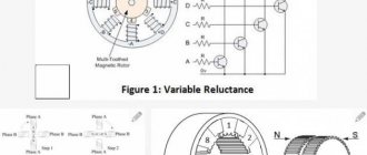
Number of Poles (Single Pole/Bipolar) Stepper motors typically have two phases, but three-phase and five-phase motors are also available. A two-phase bipolar motor has one winding/phase, while a unipolar motor has one center-tapped winding per phase. Sometimes a stepper motor is called a four-phase motor, although it only has two phases. Motors with two separate windings per phase can be driven in bipolar or unipolar mode. It is advisable that the number of wires on the motor correspond to the number of contacts on the driver, so as not to deal with various tricks when connecting.
Rated current Usually indicates the maximum current that is supplied simultaneously to both windings. The maximum current through one winding (which really matters when using microstepping) is rarely specified. When the rated current is supplied to one winding, the motor heats up; because of this, the motor current is usually limited to no more than 85% of the rated current. To achieve maximum motor torque without overheating, you must select a motor with a current rating no more than 25% higher than the recommended maximum drive current of the stepper motor.
Torque The output torque and power of a stepper motor depend on the motor size, heat sink, duty cycle, motor winding, and type of drive used. If the stepper motor is running without load over the entire frequency range, one or more natural resonance points can be detected either by sound or by vibration sensors. The useful torque from a stepper motor can be dramatically reduced due to resonances. Operation at resonant frequencies should be avoided. External damping, additional inertia, or microstepping are used to reduce the resonance effect.
Holding Torque This is the maximum torque that the motor can provide when both windings are energized at full current. Torque is proportional to current (except for very low currents), so for example if you set the drivers to 85% of the motor's rated current, then the maximum torque will be 85% * 0.707 = 60% of the specified holding torque. Torque occurs when the rotor angle differs from the ideal angle that corresponds to the current in its windings. As the stepper motor accelerates, torque is generated to overcome the rotor's own inertia and the mass of the load being driven. To produce this torque, the rotor angle must lag behind the ideal angle. Using microstepping is known to reduce torque. What this actually means is that the lag angle is equal to the angle corresponding to one microstep (since you want the position to be accurate to one microstep), a higher microstep value implies a decrease in angle and therefore a decrease in torque. The torque per unit angle (which is what really matters) does not decrease as the microstep increases. In other words, sending a pulse to the motor one 1/16 microstep results in exactly the same phase currents (and therefore the same forces) as sending two 1/32 microsteps or four 1/64 microsteps, and so on.
Size Stepper motors are also classified according to their housing dimensions, which correspond to the size of the motor frame. For example, a NEMA11 stepper motor has a frame size of approximately 1.1 inches (28 mm). Likewise, a NEMA23 stepper motor has a frame size of 2.3 inches (57 mm), etc. However, frame length may vary from motor to motor within the same size classification, and the torque of a motor with a particular frame size will increase with increasing body length.
NEMA8:
— frame dimensions 20x20 mm; — length range: 30-42 mm; — torque: 0.18-0.3 kg*cm.
NEMA11
— frame dimensions 28x28 mm; — length range: 32-51 mm; — torque: 0.43-0.9 kg*cm.
NEMA14
— frame dimensions 35x35 mm; — length range: 28 mm; — torque: 1.0 kg*cm.
NEMA16
— frame dimensions 39x39 mm; — length range: 20-38 mm; — torque: 0.65-2.0 kg*cm.
NEMA17
— frame dimensions 42x42 mm; — length range: 25-60 mm; — torque: 1.7-6.5 kg*cm.
NEMA23
— frame dimensions 56x56 mm; — length range: 41-76 mm; — torque: 2.88-18.9 kg*cm.
NEMA34
— frame dimensions 86x86 mm; — length range: 65-156mm; — torque: 34-122 kg*cm.
NEMA43
— frame dimensions 110x110 mm; — length range: 99-201 mm; — torque: 112-280 kg*cm.
NEMA51
— frame dimensions 130x130 mm; — length range: 165-270 mm; — torque: 270-500 kg*cm.
Step angle. There are two common pitch angles: 0.9 and 1.8 degrees per full step, corresponding to 400 and 200 steps/revolution. Most devices use 1.8 deg/step motors. At a given rotation speed, a 0.9 degree motor produces twice as much induced back emf as a 1.8 degree motor, due to this it may be necessary to use a 24V supply to achieve high speeds with 0.9 degree motors. 0.9 degree motors require driver step pulses to be delivered at twice the speed of 1.8 degree motors. If you are using high microstepping then the speed may be limited by the speed at which the electronics can generate the stepper pulses.
Resolution and positioning accuracy. The resolution and positioning accuracy of a stepper motor system are influenced by several factors: step angle (the length of a full step of the stepper motor), the selected motion mode (full step, half step, or microstep), and transmission speed. This means that there are several different combinations that can be used to obtain the desired resolution, because of this the resolution problem can usually be solved once the motor size and drive type have been determined.
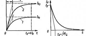
Self-induction. Motor inductance affects the speed at which the stepper motor driver can drive the motor before torque drops. If we temporarily ignore the back emf due to rotation, and the motor rated voltage is much less than the drive supply voltage, then the maximum rpm before torque drop is:
revolutions_per_second=(2*voltage_power supply)/(steps_per revolution*3.14*inductance*current)
If the motor drives the GT2 belt through a pulley, this gives the maximum speed in mm/s as:
speed=(4*number_of_pulley_teeth*voltage_power supply)/(steps_per_revolution*3.14*inductance*current)
For example: a 1.8 deg/step (i.e. 200 steps/rev) motor with an inductance of 4 mH is running at 1.5 A with a 12 V supply voltage, and the GT2 belt drive with a 20 tooth pulley begins to lose torque with speed of about 250 mm/s. In practice, the torque starts to drop earlier than this due to the back emf caused by the motion because the winding resistance is not taken into account. Motors with low inductance also have low EMF due to rotation. To achieve high speeds, it is necessary to select motors with low inductance and high supply voltage.
Resistance and Rated Voltage This is the resistance per phase and the voltage drop across each phase when the motor is stationary and the phase is carrying its rated current (which is the result of resistance and rated current). This is important when the nominal voltage is significantly lower than the supply voltage for stepper drivers.
Back EMF Due to Rotation When a stepper motor rotates, back emf is generated. At an ideal zero angle, the lag is 90 degrees not in phase with the excitation voltage, but in phase with the back EMF due to inductance. When the motor is producing maximum torque and is on the verge of skipping a step, it is in phase with the current. The back EMF due to rotation is usually not specified in the specification, but we can estimate it using the following formula:
EMF = 1.414*3.14*holding_torque*revolutions_per_second/rated_current
The formula assumes that the holding torque is specified for both phases being energized at rated current. If it is specified with only one live phase, replace 1.414 with 2. Example: Consider a 200 pitch motor driving a carriage via a 20 tooth pulley and a GT2 belt. This is a 40mm movement per revolution. To achieve a speed of 200 mm/sec we need 5 rps. If we use a motor with a holding torque of 0.55 Nm when both phases are running at 1.68.A, the peak back emf due to rotation is
1.414 * 3.142 * 0.55 * 5 / 1.68 = 7.3 V.
How to select the required supply voltage If you know in advance the required driving speed for your device, you can pre-determine what supply voltage you will need for the motor drivers. Example: let's determine the required speed. For this example we will use a 200 mm/sec, 20 tooth GT2 gear pulley. Based on the required speed of movement, we determine the maximum speed of the belt. Let's estimate the back EMF from the inductance:
voltage=steps_in_sec*3.14*motor_current*motor_EMF*N/2
where N is the number of complete steps per revolution (200 for 1.8 degree motors or 400 for 0.9 degree motors). Let's take as an example a motor with the following parameters: 0.9 degrees with an inductance of 4.1 mH, and a current of 1A. So the back emf due to inductance is:
5*3.142*1.0*4.1e-3*400/2 = 12.87 V
Let's calculate the back emf due to rotation using the formula given earlier. The example motors have a rated current of 1.68A and a holding torque of 0.44Nm, so the result is:
1.414*3.142*0.44*8.7/1.68 = 10.1 V
It is preferable that the driver supply voltage be at least the sum of these two back emfs, plus a few more volts of reserve. When using two motors in series, the required voltage doubles.
Stepper motor selection algorithm 1. Determination of the drive mechanism component. Determine the mechanism and required input data, mechanism option, approximate dimensions, travel distances and positioning times. 2. Calculate the required resolution. Find the resolution required for the engine. Based on the required resolution, determine whether a motor only or a geared motor will be used. However, thanks to the use of microstepping technology, achieving the required resolution has become much easier. 3. Define a work plan Define a work plan that matches the required data. Calculate the acceleration (deceleration) values and the operating pulse speed to calculate the acceleration torque. 4. Calculate the required torque. Calculate the load torque and acceleration torque and find the required torque required by the motor. 5. Select engine. Make a preliminary selection of the motor based on the required torque. Determine the motor being used based on its speed and torque characteristics. 6. Check the selected motor. Confirm the acceleration/deceleration rate and inertia coefficient.
General recommendations: - if you do not plan to use external stepper motor drivers, choose motors with a rated current of at least 1.2 A and no more than 2.0 A. - count on the operating current of the stepper motor to be 50-85% of the rated current.
- Size: Nema 17 is the most popular size used in home projects. Nema 23 must be used if there is not enough torque from long Nema 17 motors. - Avoid using motors with a rated voltage (or the product of rated current and phase resistance) > 4 V or inductance > 4 mH. — choose a motor with 0.9 deg/step, if additional positioning accuracy is required, for standard solutions use motors of 1.8 deg/step. - When using 0.9 degree stepper motors or high torque motors, 24V power supplies are required to maintain torque at higher speeds.
About types of engines
For a machine, the type of stepper motors used is a parameter no less important than the rest. Each model has its own characteristics.
- Bipolar ones are most often used in conjunction with CNC.
The main advantage is the ability to easily select a new driver if the old one fails. At low speeds, high resistivity is maintained.
- Three-phase.
They are characterized by high speed. Relevant if this parameter is given the most attention in the event of a choice.
- Unipolar.
These are several types of bipolar motors, which differ from each other and are selected depending on the winding connection.
Stepper Motors Overview
In the design world, stepper motors are common in 3D printing technology. All consumer 3D printers are equipped with them. Stepper motors are also widely used in robotics.
Stepper motors are widely used in robotics and 3D printers
Stepper motors are often compared to servo motors because both types of motors are used in systems that require a high level of positioning accuracy.
However, the way each type of motor tracks its position is very different. As discussed in a previous article, a servo motor contains a potentiometer that measures the absolute position of the motor. Therefore, at any given time, the servo drive knows exactly how the motor shaft is positioned. The stepper motor does not measure the angle of its shaft.
Regarding resonance at mid frequencies
Stepper motors are associated with the occurrence of strong resonance. Essentially, they work like a pendulum with a weight suspended from a spring. The role of the load is played by the rotor, and the field with magnetic energy is played by the spring. Natural vibrations have a frequency determined by two indicators:
- Rotor inertia.
- Current strength.
Resonance appears when the difference between the speed and phase of the torque reaches 180 degrees. This means that there is a correspondence between speed and changes within the magnetic field. The movement becomes fast when positioning on a new step. Torque drops because more energy is needed to overcome inertia.
How does a stepper motor work?
The design of a stepper motor is similar to a more complex version of a brushless motor. You will notice that many of the parts are essentially the same, but in a stepper motor their design is much more complex.
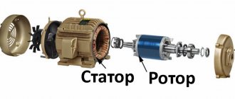
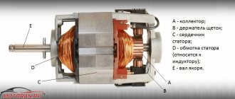
Basic Stepper Motor Components
In a stepper motor, the windings are located around the outer casing. Permanent magnets are installed on the motor shaft. Since these permanent magnets are quite heavy, a ball bearing on both sides of the motor shaft helps stabilize the motor.
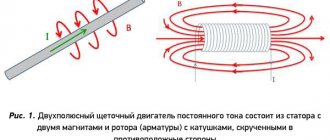
Stepper motors work in theory similar to brushless motors. To create a magnetic field, the windings are excited and, acting on permanent magnets, force the motor shaft to move.
The fins on the permanent magnets correspond to similar fins on the windings on the motor housing. Instead of rotating continuously, stepper motors move between these fins in discrete steps.
The difference with a brushless motor is that instead of turning about 30% of the circle each time the windings switch polarity, a stepper motor turns very little, typically just 1.8 degrees. Each of these tiny turns is called a step. The controllers can also control the power supplied to the windings so that the stepper motor can turn as little as 0.05625 degrees per step. This type of extremely precise motion control allows stepper motors to achieve very high positioning accuracy.
About encoders and drivers, connections
Special drivers are needed to control the device. They connect to LTP ports on personal computers. The program generates signals, which are then received by the drivers. After which the engine receives certain commands. Supplying current to the windings allows you to organize the operation of the entire device. The software makes it easier to control:
- According to motor size.
- For speed.
- Along trajectories.
The driver is a block responsible for controlling the entire engine. The control signal is generated with the participation of a special controller. Which involves connecting four terminals of the stepper motor to the device at once. Energy, negative and positive, comes from the power supply, and it is connected to the motors for further operation.
From the PU controller, signals go to the driver. Next, control of the process is organized, during which the switches that make up the circuit with the supply voltage are switched. The latter goes from the power supply to the engine, passing through the keys.
Types of stepper drives
There are two types of stepper drives:
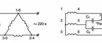
- Unipolar.
The stator windings have from 5 to 8 terminals. The engine is put into operation by switching them using a simple driver with four keys. - Bipolar.
Such a motor has only 4 outputs, and to change the parameters of the magnetic field they need a more complex control system.
Bipolar motors develop larger torques on the shaft than unipolar ones, with comparable mass-dimensional characteristics, so they can be seen much more often in CNC machines.
What else to consider?
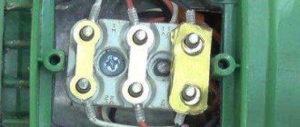
A center tap is called a regular wire. They also use the notation “. Some stepper motor models are equipped with similar devices. Each winding comes with three wires when it comes to unipolar options. Two of them organize a connection with transistors. The center tap or middle one goes straight to the power source or voltage.
The two side wires can be completely ignored if transistors are not planned to be used.
Five- and six-wire models are similar in many ways. But inside, the central wires are led out into one common cable, along with the other components. The windings cannot be connected to each other if there are no breaks. It is best to connect the middle wire with other conductors. Then you won’t have to worry about the effectiveness and safety of the device. You just need to take the appropriate parts.