Stepper Motor Types
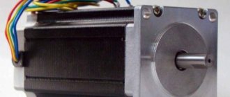
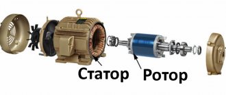
There are three main types of stepper motors: variable inductance motors, permanent magnet motors, and hybrid motors.
Variable inductance motors only use a generated magnetic field on a central shaft to cause it to rotate and be in line with the voltage of the electromagnets.
Permanent magnet motors are similar, except that the central shaft is polarized at the north and south magnetic poles, which will rotate it accordingly depending on which electromagnets are turned on.
A hybrid engine is a combination of the previous two.
Its magnetized central shaft has two sets of teeth for the two magnetic poles, which then line up with teeth along the electromagnets. Due to the double set of teeth on the center shaft, the hybrid motor has the smallest step size available and is therefore one of the most popular types of stepper motors.
Types of stepper motors by rotor type:
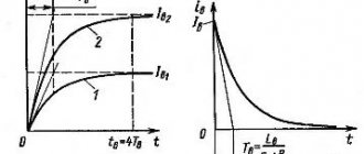
After this, the rotor will turn and will try to take one of the following equilibrium positions. To eliminate torque fluctuations when the motor is running in half-step mode, you can reduce the current at those moments when two phases are turned on.
Accordingly, in hold mode, since 8 bits of the DAC are used, the maximum current will be 1 A.
Simplified diagram of a stepper motor switch without reverse. Once again, please note: when making your own calculations, do not forget to take into account that the driver provides a mode with phase overlap, that is, it is necessary to rely on the rated current of the power circuit, equal to twice the maximum current of the windings at the selected supply voltage. Because of these limitations, microstepping is used primarily to ensure smooth rotation especially at very low speeds, to eliminate noise and resonance phenomena.
Dependence of torque on the angle of rotation of the rotor for two powered windings. They usually have four terminals and two windings.
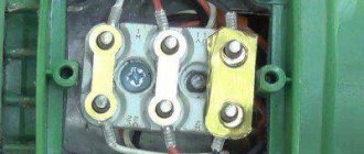
In full-step mode with two phases turned on, the positions of the rotor equilibrium points are shifted by half a step. The middle terminals of the windings can be combined inside the motor, so such a motor can have 5 or 6 terminals Fig.
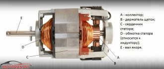
The purpose of these diodes is to suppress the self-induction emf that occurs when the control switches are turned off. When the current is turned on in one of the coils, the rotor tends to take a position where the opposite poles of the rotor and stator are opposite each other. And in modern household appliances, cars, and industrial equipment, commutator motors are quite common.
If at least one winding of the stepper motor is energized, the rotor takes a certain position. But it is impossible to extract such current from the 74HCxx series microcircuits, so additional drivers will be required.
Provides the passport value of electrical characteristics. Drivers are divided into two categories: Those that follow the waveform. The rotor does not have permanent magnets; it is made of soft magnetic material in the form of a multi-pointed star. Magnetic hysteresis leads to the fact that the magnetic flux depends not only on the winding current, but also on its previous value. From the point of view of the author of the article, the most optimal way to control the switching of low-power motor windings is to use an RDC ON MOSFET that is suitable for the current and open channel resistance, but taking into account the recommendations described above. Stepper motor. Micro Step Driver. PLC Omron. Connection, programming. (Part 1)
Unipolar and bipolar stepper motors
There are also two more types of stepper motors: unipolar and bipolar . At a fundamental level, these two types work exactly the same; The electromagnets are connected in series, causing the central motor shaft to rotate.
But a unipolar stepper motor works only with positive voltage, while a bipolar stepper motor has two poles - positive and negative.
So the actual difference between the two types is that unipolar requires an extra wire in the middle of each coil, which will allow the current to flow to either one end of the coil or the other. These two opposing directions produce two polarities of the magnetic field, effectively simulating both positive and negative voltages.
Although they both have a common supply voltage level of 5V, a bipolar stepper motor will have more torque because current flows through the entire coil, producing a stronger magnetic field. On the other hand, unipolar stepper motors only use half the length of the coil due to the extra wire in the middle of the coil, meaning less torque is available to hold the shaft in place.
How does a hybrid engine work?
The workings of a hybrid stepper motor can be easily understood by looking at a very simple model that produces 12 steps per revolution.
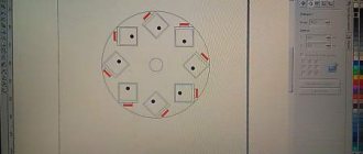
The rotor of this machine consists of two parts, each of which has three teeth. Between the two parts there is a permanent magnet, magnetized in the direction of the rotor axis, thus creating a south pole on one part of the part, and a north pole on the other. The stator consists of a tube having four teeth inside it. The stator windings are wound around each such tooth.
When current flows through one of the windings, the rotor takes one of the positions shown in the figures. This is due to the fact that the permanent magnet of the rotor tries to minimize the magnetic resistance of the winding. The torque that tends to hold the rotor in these positions is usually small and is called “torque relaxation.” Below is a 12 step motor diagram.
If current flows through the two stator windings, the resulting poles will attract the teeth of reverse polarity at each end of the rotor. There are three stable positions for the rotor, the same as the number of teeth on the rotor. The torque required to move the rotor from its stable position into rotating motion is called "torque hold"
By changing the current of the first to the second winding (B), the magnetic field of the stator rotates 90 degrees and attracts a new pair of rotor poles. As a result, the rotor rotates 30 degrees, which corresponds to a full pitch. Returning to the first set of stator windings, but with reverse polarity supply, changes the stator magnetic field by another 90 degrees, and the rotor turns 30 degrees (C).
Finally, the second set of windings works in the opposite direction, providing a third rotor position (another 30 degrees). Now we can return again to the first stage (A), and after going through all these four stages again, the rotor will be moved one more tooth.
Obviously, if the polarity of the power supply to the windings is opposite to that described, then the rotation of the motor will also change to the opposite.
Connecting stepper motors
Different stepper motors may have different numbers of wires, typically 4, 5, 6, or 8. Only bipolar stepper motors can support 4-wire lines because they do not have a center wire.
5 and 6 wire mechanisms can be used for both unipolar and bipolar stepper motors, depending on whether a center wire is used on each coil or not. The 5-wire configuration means that the central wires for two sets of coils are connected internally to each other.
HOW TO CONNECT A STEPPER MOTOR
Stepper motors can be supplied with several connection options. The choice of circuit will be determined by the type of engine. Most of the most common stepper motors have circuits that use 4, 5, 6 or 8 wires.
Let's start by showing how to connect a 4-pin stepper motor. If you have a stepper motor with only four wires, that means you can only use it with a bipolar driver. Please note that each of the phase windings contains a pair of wires - use a tester (multimeter) to identify each wire.
Find the shorted wires and connect them to the stepper motor.
Ways to control stepper motors
There are several different ways to control stepper motors - full step, half step, and microstep. Each of these styles offer different torques, pitches and sizes.
Full step - such a drive always has two electromagnets. To rotate the shaft, one of the electromagnets is turned off and then the electromagnet is turned on, causing the shaft to rotate 1/4 tooth (at least for hybrid stepper motors). This style has the strongest torque but also the largest step size.
Half a step . To rotate the central shaft, the first electromagnet is energized as the first step, then the second is also energized, and the first one is still running for the second step. In the third step, the first electromagnet is turned off and the fourth step is a turn to the third electromagnet, and the second electromagnet is still working. This method uses twice as many steps as a full step, but it also has less torque.
Microstepping has the smallest step size of all these styles. The torque associated with this style depends on how much current is flowing through the coils at a given time, but it will always be less than at full pitch.
Where to buy a stepper motor
The simplest engines Options on the AliExpress website:
| Stepper motor Nema17 42BYGH 1.7A (17HS4401-S) for 3D printer | Set of 5 stepper motors ULN2003 28BYJ-48 with driver boards for Arduino | Stepper motor with driver module 5V Stepper Motor 28BYJ-48 + ULN2003 |
| Another stepper motor option for Arduino 28BYJ-48 5V 4 Phase DC Motor + ULN2003 Drive Test Board | Set of three stepper motors Nema17 Stepper Motor 42BYGH 1.7A (17HS4401) for 3D printer | AliExpress.com Product – 3D Printer Parts StepStick A4988 DRV8825 Stepper Motor Driver With Heat sink Carrier Reprap RAMPS 1.4 1.5 1.6 MKS GEN V1.4 board |
Stepper motor connection diagram
To control a stepper motor you need a controller. The controller is a circuit that supplies voltage to any of the four stator coils. The control circuits are quite complex compared to conventional electric motors, and have many features. We will not consider them in detail here, but will simply present a fragment of a popular controller based on ULN2003A.
In general, stepper motors are a great way to turn something to a precise angle with a lot of torque. Another advantage of them is that the speed of rotation can be achieved almost instantly when the direction of rotation is reversed.
Read also: Specific gravity of lead g cm3
The article details several ways to update the BIOS on an Asus motherboard.
Now you can definitely choose the ideal laptop for work or study!
This article describes the benefits of SSD drives for applications and games. There is also a comparison between the advantages of this drive with its outdated counterpart.
The article talks about how to repair a plastic Chinese electric kettle.
Step 1.
From the old scanner:
- 1 stepper motor
- 1 chip ULN2003
- 2 steel rods
For the case: – 1 cardboard box
- Glue gun
- Wire cutters
- Scissors
- Soldering Accessories
- Dye
- 1 DB-25 connector - wire
- 1 x DC cylindrical socket For test bench
- 1 threaded rod
- 1 nut that fits the rod - various washers and screws - pieces of wood
For the control computer:
- 1 old computer (or laptop)
- 1 copy of TurboCNC (from here)
Step 2.
We take parts from an old scanner. To build your own CNC controller, you first need to remove the stepper motor and control board from the scanner. There are no photos here because each scanner looks different, but usually you just need to remove the glass and remove a few screws. In addition to the motor and board, you can also leave metal rods that will be required for testing the stepper motor.
Step 3.
Removing the chip from the control board Now you need to find the ULN2003 chip on the stepper motor control board. If you were unable to find it on your device, ULN2003 can be purchased separately. If there is one, it needs to be desoldered. This will require some skill, but is not that difficult. First, use suction to remove as much solder as possible. After this, carefully insert the end of a screwdriver under the chip. Carefully touch the tip of the soldering iron to each pin while continuing to press down on the screwdriver.
Step 4.
Soldering Now we need to solder the chip onto the breadboard. Solder all pins of the microcircuit to the board. The breadboard shown here has two power rails, so the positive pin of the ULN2003 (see the diagram here and in the picture below) is soldered to one of them, and the negative pin to the other. Now, you need to connect pin 2 of the parallel port connector to pin 1 of the ULN2003. Pin 3 of the parallel port connector connects to pin 2 of the ULN2003, pin 4 to pin 3 of the ULN2003, and pin 5 to pin 4 of the ULN2003. Now pin 25 of the parallel port is soldered to the negative power rail. Next, the motor is soldered to the control device. This will have to be done through trial and error. You can simply solder the wires so that you can then attach crocodiles to them. You can also use screw terminals or something similar. Simply solder wires to pins 16, 15, 14 and 13 of the ULN2003 chip. Now solder a wire (preferably black) to the positive power rail. The control device is almost ready. Finally, connect a cylindrical DC jack to the power rails on the breadboard. To prevent the wires from breaking off, they are secured with glue from a gun.
Step 5.
Installing the software Now about the software. The only thing that will definitely work with your new device is Turbo CNC. Download it here. Unpack the archive and burn it to CD. Now, on the computer you are going to use for management, go to the C:// drive and create a “tcnc” folder in the root. Then, copy the files from the CD to a new folder. Close all windows. You have just installed Turbo CNC.
Step 6.
Software setup Restart your computer to switch to MS-DOS. At the command prompt, type "C:cncTURBOCNC". Sometimes it is better to use a boot disk, then a copy of TURBOCNC is placed on it and you need to type “A: cncTURBOCNC” accordingly. A screen similar to the one shown in Fig. will appear. 3. Press Spacebar. Now you are in the main menu of the program. Press F1, and use the arrow keys to select the "Configure" menu. Use the arrow keys to select "number of axis". Press Enter. Enter the number of axes to be used. Since we only have one motor, we select “1”. Press Enter to continue. Press F1 again and from the Configure menu select Configure axes, then press Enter twice.
The following screen will appear. Press Tab until you reach the "Drive Type" cell. Use the down arrow to select "Phase". Use Tab again to select the "Scale" cell. To use the calculator, we need to find the number of steps the motor makes in one revolution. Knowing the engine model number, you can determine how many degrees it turns in one step. To find the number of steps the motor makes per revolution, you now need to divide 360 by the number of degrees per step. For example, if the motor rotates 7.5 degrees in one step, 360 divided by 7.5 equals 48. Enter the number you get into a scale calculator.
Leave the rest of the settings as they are. Click OK, and copy the number in the Scale cell to the same cell on another computer. Set the Acceleration cell to 20 because the default of 2000 is too high for our system. Set the initial speed to 20 and the maximum speed to 175. Press Tab until you reach the “Last Phase” item. Set it to 4. Press Tab until you reach the first row of X's.
Read also: Hammering a dowel into concrete
Copy the following into the first four cells:
1000XXXXXXXX 0100XXXXXXXX 0010XXXXXXXX 0001XXXXXXXX
Leave the remaining cells unchanged. Select OK. You have now configured the software.
Step 7
Building a test shaft The next stage of work will be to assemble a simple shaft for the test system. Cut 3 pieces of wood and fasten them together. To get straight holes, draw a straight line on the surface of the wood. Drill two holes on the line. Drill 1 more hole in the middle below the first two. Disconnect the bars. Thread steel rods through two holes that are on the same line. Use small screws to secure the rods. Thread the rods through the second block. Secure the engine to the last block. It doesn't matter how you do it, be creative.
To secure the engine that was available, two pieces of 1/8 threaded rod were used. A block with an attached motor is placed on the free end of the steel rods. Secure them again with screws. Thread a threaded rod through the third hole on the first block. Screw the nut onto the rod. Pass the rod through the hole in the second block. Rotate the rod until it goes through all the holes and reaches the motor shaft. Connect the motor shaft and rod using a hose and wire clamps. On the second block, the nut is held in place with additional nuts and screws. Finally, cut a piece of wood for the stand. Screw it to the second bar with screws. Check that the stand is installed level on the surface. The position of the stand on the surface can be adjusted using additional screws and nuts. This is how the shaft for the test system is made.
Step 8
Connecting and testing the motor Now you need to connect the motor to the controller. First, connect the common wire (see the motor documentation) to the wire that was soldered to the positive power bus. The other four wires are connected through trial and error. Connect them all, and then change the connection order if your motor takes two steps forward and one step back or something similar. To test, connect a 12V 350mA DC power supply to the barrel jack. Then connect the DB25 connector to the computer. In TurboCNC, check how the motor is connected. As a result of testing and verifying that the motor is connected correctly, you should have a fully functional shaft. To test your device's scaling, attach a marker to it and run a test program. Measure the resulting line. If the line length is about 2-3 cm, the device is working correctly. Otherwise, check the calculations in step 6. If you succeeded, congratulations, the hardest part is over.
Step 9
Case manufacturing
Part 1
Making the body is the final stage. Let's join the environmentalists and make it from recycled materials. Moreover, our controller is also not from store shelves. The sample board presented to your attention measures 5 by 7.5 cm, so the case will measure 7.5 by 10 by 5 cm to leave enough space for the wires. Cut out the walls from a cardboard box. Cut out 2 rectangles measuring 7.5 by 10 cm, 2 more measuring 5 by 10 cm and 2 more measuring 7.5 by 5 cm (see pictures). You need to cut holes in them for the connectors. Trace the outline of the parallel port connector on one of the 5 x 10 walls. On the same wall, trace the contours of a cylindrical socket for DC power. Cut out both holes along the contours. What you do next depends on whether you soldered the connectors to the motor wires. If yes, then attach them to the outside of the second currently empty 5 x 10 wall. If not, poke 5 holes in the wall for the wires. Using a glue gun, connect all the walls together (except the top, see pictures). The body can be painted.
Step 10
Case manufacturing
Part 2
Now you need to glue all the components inside the case. Make sure to get plenty of glue on the connectors because they will be subject to a lot of stress. To keep the box closed, you need to make latches. Cut out a couple of ears from foam plastic. Then cut out a couple of strips and four small squares. Glue two squares to each of the strips as shown in the picture. Glue the ears on both sides of the body. Glue stripes on top of the box. This completes the manufacture of the body.
Step 11
Possible applications and conclusion This controller can be used as: – CNC device – plotter – or any other thing that needs precise motion control. - Addendum - Here is a diagram and instructions for making a three-axis controller. To configure the software, follow the above steps, but in the "number of axis" field, enter 3.
To configure the first axis, do everything as stated above, for the second axis too, but in the lines of the first four phases, enter the following:
"XXXX1000XXXX XXXX0100XXXX XXXX0010XXXX XXXX0001XXXX"
For the third axis, in the lines of the first four phases, enter:
"XXXXXXXX1000 XXXXXXXX0100 XXXXXXXX0010 XXXXXXXX0001"
Translation: Piyavka, commissioned by RadioLotsman
| Discussion fragments (last 20 messages only): | Full discussion » |
- From the “DIY CNC machine” series. In principle, the information is already known, only the software used is ancient (of course suitable for experiments). And in the photo there is a TD62803 chip (it looks like an analogue).
- The software runs under MS-DOS, but maybe this controller can work under Windows XP.
- If the OS allows you to communicate directly with the LPT port, then you can try running this program under Windows (from the command line).
- I understand, of course, that I want to try SD. A few years ago I didn’t know how to approach him. But the desire to try means to apply it somewhere. Best suited for first experiments: software MACH-2 Controller on L297 + 4 IRF640 field workers, for example. (preferably with drivers). There must be 2 optocouplers at the input of your magic design. If you close it too much, it won’t burn out. The computer will definitely survive. And good luck.
- I soldered the controller to unl2003, how can I check it now before connecting it to the computer..
- but without optocouplers it’s not like
- It is possible, but only for the first experiments. And it’s easy to check. Take it and turn on an incandescent light bulb instead of the windings. And you will see everything at slow speed.
- This is to put light bulbs in place of optocouplers.
- Optocouplers are still like the moon. Instead of windings - Light bulbs.
- and you don’t have a simple controller circuit.
- In my opinion, this is the simplest scheme, much simpler, especially since you have already assembled it. It remains to check, there is a lot of information on this ULN2003 driver
- The circuit works but only 2 engines. for 3 motors which is connected to 1,14,16,17. Why is 1 input not working? And I can’t figure out the turbo cnc program. Is there such a thing only in Russian?
- Is the ULN2003 driver connected to these outputs working? Did you set up as described in the article?
- Help me figure out the turbo cnc program. Is there another program in Russian for the controller on uln2003.
- Here there is a program for Win and a lot of useful information regarding stepper motors
- I’m making a second controller for 555tm7 and uln2004. but there is one problem with the circuit: it’s uln2004 and is it possible to replace it with uln2003? if possible, what is the difference between them.
- The microcircuits are interchangeable, the only difference: ULN2003 can be controlled by TTL and CMOS signals, and ULN2004 - only CMOS (6-15 V). I think so, if my memory serves me correctly. It’s better to download the datasheet on them and compare.
- Hello ! Help, who can! How to control one computer or controller simultaneously with hundreds of stepper motors?
- Are there too many stepper motors for one “brain”. An alternative is to use a port expander for the microcontroller and stepper motor drivers, or special stepper motor drivers with a serial interface and addressing.
- Is it possible to connect a stepper motor to the specified circuit if it has not 5 but 4 outputs (M49SP-2NK) AND IF YES, HOW
Read also: What is a miter box used for?
| Full discussion » |
| Recommended publications on the topic: |
| Scheme | » |
When reprinting materials from the site, direct
A link to RadioLotsman is required.
We invite authors of articles and translations to publish materials on the pages of the site.
Starting a stepper motor without electronics
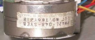
Any radio amateur often accumulates quite a few different office equipment that are out of order. No one dares to throw it away, since something useful can be made from its insides or some parts can be removed. For example: a stepper motor , which is so common, is usually used by DIY enthusiasts as a mini generator for a flashlight or for something else. But I have almost never seen it used specifically as a motor to convert electrical energy into mechanical energy. This is understandable: to control a stepper motor you need electronics and you can’t just connect it to voltage.
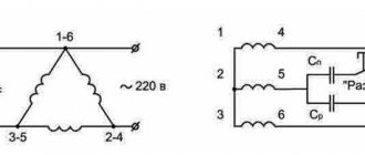
But it turns out that this opinion is wrong. A stepper motor from a printer or other device can be easily started from alternating current.
The following stepper motor :
They usually have four terminals and two windings in most cases, but there are others of course. In this case, the most popular engine .
Bipolar Stepper Motor Controller
The circuit represents a low-cost and, above all, easy-to-assemble alternative to available microprocessor-based bipolar stepper motor controllers. Recommended where control accuracy plays a lesser role than price and reliability.
The circuit diagram can be divided into the following blocks:
- serial chip generating bit strings,
- local clock generator,
- coil power control circuit,
- H-bridge output buffers,
- protection circuits for input control signals.
The controller must be powered by a constant voltage, well filtered, preferably stabilized.
Now a few words about the H-bridges that will work with this driver. They must accept all possible logic states (00, 01, 10, 11) at their inputs without risk of any damage. It’s just that in some configurations of bridges built from discrete elements, simultaneous activation of two inputs is prohibited - they naturally cannot be used with this controller. Bridges made in the form of integrated circuits (for example L293, L298) are resistant to this.
And finally, the third version of the controller, based on STK672-440 microcircuits, has all the necessary protections and functions, see the link.
Operating modes of stepper motors:
- To operate a stepper motor (regardless of its type), you can select one of three operating modes:
- Full-step mode - the rotor rotates 1 step per 1 clock cycle.
- Half-step mode - the rotor rotates ½ step per 1 clock cycle.
- Microstepping mode - the rotor rotates ¼, ⅛, etc. steps per 1 clock.
Read also: Stopper for drilling holes for an eccentric coupler
The operating modes are discussed below, using the example of a bipolar motor with a permanent magnet and a full pitch of 90°.
Full-step mode (one phase per full step). The nominal values of the stepper motor are indicated specifically for this mode.
Full-step mode (two phases per full step). This mode allows you to increase the torque by almost half of the nominal one.
Half-step mode. This mode allows you to double the number of steps in a full rotation, with a slight decrease in torque.
Microstepping mode. This mode is the most common; it allows you to increase the number of steps in a full rotation by four times, due to the uneven distribution of currents in the windings. Reducing currents can be achieved by reducing the voltage (as shown in the picture) or by applying full voltage through a connected external load.
If you feed the levels not “0” – “½” – “1” (as in the picture), but “0” – “¼” – “½” – “¾” – “1”, then the number of steps in a full revolution will not increase 4 times, and 8 times. You can increase the number of steps by 16, 32, 64 times, etc., and if you replace the discrete signal levels with sinusoids, the motor will rotate smoothly (without steps).
Low Power Modes – Available for 8-pin motors only. These modes differ from conventional ones in that they use only half the phase (half the electromagnets). These modes are rarely used, as they significantly reduce engine torque.
