Design and principle of operation of a push-button control station
The push-button station is designed for switching circuits designed to control alternating current, the voltage of which is up to 660 V with a frequency of 50 and 60 Hz. In addition, they can be used in DC circuits with voltages up to 440 V or for supplying control signals. The latter can be performed either remotely or on site.
Typically, such products are needed to control devices of various types at a distance.
The design of the control panel is quite simple , there are a minimal number of parts in it, but there is one very important function - to issue commands and check how completely they have been executed.
They are used in automatic systems, in particular, such devices can be placed in metal and woodworking machines, various types of mechanisms aimed at lifting and moving loads.
Its body is usually made of plastic, there are at least 2 control elements, but there can be much more.
Its pusher is mushroom-shaped or made in the shape of a cylinder. Cylindrical products are available in black, white, yellow, red, blue or green. The mushroom-shaped pusher is painted red or black.
The contact elements operate via both the making and breaking principles.
Explosion-proof models are used to remotely control electric drives of stationary or mobile installations. These devices can be used in the gas and oil industries, as well as in other types of industrial production.
This system is quite flexible and is equipped with several modules, as well as a magnetic starter. The latter is connected directly through a push-button post, due to which the reliability of its operation becomes very high.
This starter is a switching structure, due to which electricity is disconnected or connected.
Such starters have a metal or plastic body and can be used in direct or alternating current networks. They are often used in automated systems and devices; in addition, they are designed to turn systems on or off in the event of an emergency.
They can be remote or built directly into the design of the product.
Push-button post: purpose and diagram
Push-button post
— designed for switching electrical control circuits of alternating current voltage up to 660 V, frequency 50 and 60 Hz and direct current voltage up to 440 V, and/or supplying control signals, both locally and remotely; used for remote control of various mechanisms and electrical machines. This is a simple product, consisting of a minimum number of parts, but with a very important function - issuing commands and indicating their execution.
The use of push-button posts is quite diverse and, accordingly, it has different types and designs. Example: control station for a hoist (it would be more correct, of course, to call it “control panel”) Fig.
1 . Using this type of starter, the operation of various traction mechanisms is controlled. These are mainly crane, elevator escalator, beams, etc.
However, the topic of this article will be a standard push-button station for controlling various power devices (mainly various electric motors). “Start-Stop” push-button post, I’ll immediately note that the circuit is applicable not only to magnetic starters but also to any type of relay. So, what is a “button post”? The “button post” structurally consists of a housing and two buttons “Start” and “Stop”. The appearance of buttons for push-button posts is shown in Fig. 1
.
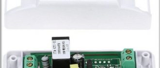
Figure 2
shows the body of the push-button post.
- Both buttons are without fixed position.
- The “Start” button (usually green and may be backlit when turned on) has normally open contacts and is designed to turn on the CM;
- The “Stop” button (usually red) has normally closed contacts and is designed to relieve voltage from the CM;
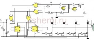
The on-off circuit is shown in Fig. 4
. nothing complicated: when contacts SB1.1 are closed, voltage is supplied to the coil of the contactor KM1 and it is activated, while the contacts SB1.1 of the “Start” button are blocked by the normally open contacts (NO) KM1.4 of the contactor KM1. That's it, the power contacts of the KM1 contactor are closed and voltage is supplied to the power plant. You can release the “Start” button and the power unit will remain energized (will not turn off), since the KM1.4 contacts connected in parallel to the “Start” button are closed and the KM1 starter coil is constantly on. It turns out that after releasing the “Start” button, the phase continues to flow to the coil of the magnetic starter, but through its own pair of contacts KM1.4. To stop the mechanism, use the “Stop” button; when it is pressed, the contacts ST2 open, the voltage from the coil of the contactor KM1 is removed, its contacts KM1.4 open and at the same time unlocking, thereby unlocking the contacts of the “Start” button, the engine is stopped. In Figure 5, the arrow shows the movement of phase “L3” (any of the phases can be selected arbitrarily to power the magnetic contactor coil).
There may be several switching points for a particular system (for example, a ventilation system...). The connection diagram for several push-button posts is shown in Fig. 6
.
With such a switching circuit, the “executive” magnetic contactor (KM 1) can be either turned on or off from any of the “posts”; in such a circuit, it is of course desirable to backlight the start button so that the state of the system can be seen from any of the posts. As you understand, dear reader, the “Start” and “Stop” buttons provide both local (from the control and automation panel) and remote control of the magnetic starter, and therefore the load it switches. Moreover, instead of a motor, you can connect any load, for example, a powerful heating element.
Well, that's all, if you have any questions, use our email
.
Let's try to answer them competently. In the subject line of the email, write: “Irrigation systems.” PS
please do not ask questions that will be answered: “read the article carefully.”
We connect the magnetic starter via a push-button station, the “Start” and “Stop” buttons. For those who read electrical diagrams and can imagine how a circuit works in dynamics, connecting a magnetic starter will not be difficult. The site has repeatedly received requests to suggest how to connect the starter to an engine with start-stop buttons to a 220V network.
I will try to explain literally in my fingers what goes where and why. It is difficult to understand the wiring diagram at first glance. Everything will be clear when you carefully study the circuit, but not all at once, but piece by piece, element by element, asking yourself what role this contact or element plays in the circuit.
At the same time, studying the circuit, find, for example, the control coil of a magnetic starter and its contact terminals. Find power contacts on the starter - working contacts, auxiliary contacts (normally open and normally closed) necessary for blocking or bypassing contacts.
Disassemble the push-button post and understand the principle of operation. When you press a button, one contact closes and the other opens. Find the contacts in the wiring diagram and on the elements - starter and push-button post. Only after simultaneously studying the circuit and its elements will the logic and operating principle of the circuit be understood.
Device and design
simple post scheme
The standard push-button control station has the following design features:
If the equipment is dangerous to human life or health, similar devices are produced with an increased degree of protection. The connection diagram in this case is much more reliable, and the remote control itself can be connected to various devices.
Often, the installation is controlled from 2 points. As a rule, this is caused by a certain production need. Typically, various electric motors operate using this technology, but other equipment can also operate.
Operating principle
Such a device is a switching device, thanks to which the electric current is controlled and distributed along the circuits to which it is connected.
On the one hand, at the push-button station there are power contacts, which perform switching on, switching, normal and emergency shutdown of the equipment.
On the other hand, an electromagnetic coil is installed, due to which these contacts are switched on and off:
Advantages
The main positive aspects of its operation are:
Largely due to all these advantages, push-button posts have one of the highest degrees of protection.
Main types:
Typically used when working with woodworking devices for both industrial and domestic purposes.
Used in industry where there is no threat of explosion, and the total concentration of dust or gas will not lead to failure of such equipment.
Used when working with electrical equipment installed on mechanisms capable of lifting large loads, for example, beam cranes, overhead cranes, and so on. With the help of such a device, the tool will be controlled from the surface of the earth in manual mode.
How to connect a magnetic starter. Connection diagram.
March 02, 2014 | Section: Electrics
Hello, dear readers of the site sesaga.ru. We continue to deal with the magnetic starter . In the first part of the article, we got acquainted with the device, purpose and operation of a magnetic starter, and today we will look at its electrical connection diagram .
But before assembling the circuit, let's make a small digression and get acquainted with one important element of the magnetic starter control circuit - the button
.
As you may have guessed, the “Start”, “Stop”, “Forward”, “Back” buttons remotely control the magnetic starter, and therefore the load that it switches. Control buttons are available in two types: with opening
and
a normally open
contact.
Stop button.
The "Stop" button is easy to distinguish by its red color
blossom.
The button uses a break
(normally closed) contact through which the supply voltage passes to the starter control circuit.
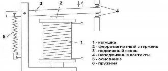
In the initial position when the button is not pressed
, the moving contact of the button is pressed from below by a spring and
closes
two fixed contacts, connecting them to each other. And if the button is in an electrical circuit, then at that moment current flows through it. When it is necessary to open the circuit, the button is pressed, the moving contact moves away from the fixed contacts and the circuit opens.
When released, the button again returns to its original position by a spring that presses the movable contact, and it again closes both fixed contacts. The figure shows the button contacts in the pressed and not pressed position.
Modern control buttons and push-button posts - types and types
For remote control of various electrical devices and machines, control buttons and push-button stations are used. Most often, these means are used to control equipment that uses electric motors as drives. Thus, the operator does not need to climb onto the crane beam in order to bring the hook to the desired place on the workshop territory; instead, he just needs to press the appropriate button on the control panel, and the crane itself will go where the operator indicates.
In a similar way, the power supply and operating modes of machines, fans, pumps, etc. are controlled. Buttons and push-button stations can be located at the operator’s workplace, forming a specialized remote control for solving specific problems related to the control of equipment at a given enterprise.
A button is an electrical command device consisting of a push-button (contact) and drive element and is intended primarily for manual remote control of electromagnetic devices.
Buttons are used in AC circuits with a voltage of no more than 660 V and DC circuits of no more than 440 V. There are two types: monoblock, in which the contact element and drive are mounted in a single block, and double-block, in which the drive (pusher, handle, lock with a key) is installed on a separate plate, and the push-button element is mounted on the base under the drive element. Buttons can have from 2 to 8 contacts, and the number of normally open contacts is usually equal to the number of normally closed ones.
After the pressure on the drive element stops, it, together with the contacts, returns to its original position under the action of return springs. There are buttons without self-return - with a mechanical or electromagnetically controlled latch. Modern button designs use bridge-type moving contacts with a double circuit break. The contact material is silver or metal-ceramic compositions.
The continuous current and switched alternating current do not exceed 10 A. The pressing force on the button drive is 0.5 - 2 kg. For safety reasons, the button pushers that execute the “stop” command protrude 3–5 mm above the level of the console cover where they are installed, and the buttons that execute the “start” command are recessed to the same distance.
According to the degree of protection from environmental influences, buttons are distinguished into open, protected and dust- and water-proof versions. Several buttons built into one shell or installed on one cover form a button post (station).
Push-button stations are designed to turn electrical devices on and off, to change the direction of rotation of drives in devices, for manual emergency shutdown of equipment in emergency situations, etc. - depending on the purpose of a particular electrical equipment.
In general, it can be noted that for different tasks, push-button stations are made in different housings and with different numbers of buttons, however, one feature is fundamentally important - push-button posts are not used in high-voltage circuits; they, of course, can control high-voltage equipment, but they themselves work in circuits with voltage up to 600 volts alternating or up to 400 volts direct.
Often, the current through the push-button station is not the operating current of the installation. The switching of power circuits is carried out by the starter, but the starter is controlled by a push-button station.
For example, connecting an asynchronous motor to the network directly or in reverse is controlled by a magnetic starter, and the starter is controlled by the operator using a three-button control: “start forward”, “start reverse”, “stop”. When you press the “start” button, the normally open contacts of the starter close according to the direct engine start circuit, and when you press the “reverse start” button, the contacts change configuration to reverse. “Stop” – the starter opens the power circuit.
The number of buttons on a button post is determined by the purpose of the consumers and their number. So, posts can be two-button and multi-button. In its simplest form, there are only two buttons: “Start” and “Stop”. And sometimes one button, installed for example on a lathe, is enough.
The buttons can be located in a metal or plastic case, which in turn is mounted in a place more convenient for use. Separately, you can select posts for controlling crane beams (PKT posts - push-button telpher post).
The main element of the push-button station is the push button. Push buttons come in two types: self-returning and latching. Self-resetting ones are pushed to their original state by a spring - the operator pressed the “Stop” button - the “Start” button returned to its original state, and those with a fixation - only after pressing again - until you press again - the contacts open.
An example of a push-button post with fixation is the popular two-button post: the “Stop” button is pressed - the contacts are open, the “Start” button is in the free state. The “Start” button is pressed – the contacts are closed, and the “Stop” button is in the free state. These posts serve a wide variety of applications, and they often control magnetic starters rather than directly supplying current.
Start button.
Typically, the Start button is painted black.
or
green
colors.
The button uses open
(normally open) contact, which, when closed, causes electric current to flow through the button.
The “Start” button is designed in the same way as the “Stop” button, and differs only in that in the initial position its moving contact does not close
fixed contacts - that is, it is always in
an open
state. On the left side of the figure you can see that the moving contact is not closed and is pressed upward by the spring.
When you press the button, the moving contact moves down and closes both fixed contacts. When the button is released, its movable contact, under the action of a spring, returns to its original upper position and the contacts open.
Buttons and push-button posts: purpose and types
Control buttons or push-button stations are special devices that are used for the purpose of remote control of various electrical installations and devices, machines and machine tools. Basically, buttons and posts are used with electrical equipment where the drives are electric motors.
Thanks to buttons and push-button stations, the operator is freed from the need to climb onto the crane in order, for example, to move the hook to the desired location. To perform such a task, you just need to use one button. This is how machines, pumps and other large equipment are controlled.
The necessary buttons and posts are located at the workplace in such a way that they form a single control panel designed to solve certain problems at a specific enterprise.
What is a button?
Buttons are an electrical device, the design of which includes a push-button element and a drive element. The main purpose is manual remote control of equipment and devices. Buttons are used in AC electrical circuits, the maximum voltage of which is 660 V, as well as in DC circuits with a voltage of 440 V.
Blocks are divided into two types:
- monoblock - the drive and contacts are in one block;
- two-block - the drive is mounted on a separate plate, and the button is located under the drive.
Buttons have from two to eight contacts. In this case, the number of normally open and normally closed contacts must be the same.
After the pressing stops, the drive element returns to its original position. But among the huge number of modern buttons and push-button posts, there are those that do not have self-return, but are equipped with a mechanical or electromagnetic latch. Modern models of buttons are equipped with movable contacts made of silver or metal ceramics. The type of these contacts is bridge with double circuit break.
Operational safety is ensured by the fact that the pushers of the stop command buttons protrude 3-5 mm above the control panel cover. The “start” buttons, in turn, are recessed into the lid to the same depth.
Modern buttons and push-button posts differ in the degree of protection from environmental influences. Thus, there are open type buttons, as well as those protected from dust and moisture.
What is a push-button post?
A station or push-button post is a number of different buttons that are combined under a single shell.
The purpose of the push-button station is to turn off and on electrical equipment, change the direction of rotation of electric drives, for emergency shutdown of devices, etc.
Push-button stations are manufactured in different housings and with different numbers of buttons, which directly depends on the tasks assigned to the stations. There is one special feature - push-button stations are not used in high-voltage circuits, but they can work with high-voltage equipment. The operation of push-button stations occurs in alternating voltage circuits up to 600 and DC up to 400 V. The starter acts as a switching power circuit, which, in turn, is controlled by a push-button station. Let's give an example: a magnetic starter controls the connection of an asynchronous type electric motor to the electrical network (either directly or in reverse); The starter is controlled using a post.
The number of buttons in a button post is determined by the number of consumers, as well as their quantity. Thus, the push-button station can be two-button or multi-button. The simplest version of the post is two buttons (“start” and “stop”). It also happens that one button is used.
The main element of any push-button post is the push button. These buttons are divided into two types: with a self-return function and with the possibility of fixation.
Self-returning push buttons return to their original position using a special spring. That is, when you press the “stop” button, the “start” button returns to its original position. If the push button is fixed, the contacts will open only when pressed again.
Magnetic starter connection diagrams.
The first, classic scheme, is intended for the usual start of an electric motor: the “Start” button is pressed - the engine turns on, the “Stop” button is pressed - the engine turns off. Moreover, instead of a motor, you can connect any load, for example, a powerful heating element.
For ease of understanding, the circuit is divided into two parts: power part
and
control circuits
.
Power section
powered by three-phase alternating voltage 380V with phases “A” “B” “C”.
The power part includes: three-pole circuit breaker QF1
, three pairs of power contacts of the magnetic starter
1L1-2T1
,
3L2-4T2
,
5L3-6T3
and a three-phase asynchronous electric.
engine M.
_
Control circuit
receives power from phase “A”.
The control circuit diagram includes the SB1
“Stop” button, the
SB2
“Start” button, the magnetic starter coil
KM1
and its auxiliary contact
13NO-14NO
, connected
in parallel with
the “Start” button.
When turning on the QF1
phases “A”, “B”, “C” arrive at the upper contacts of the magnetic starter
1L1
,
3L2
,
5L3
and are on duty there.
Phase “A”, which supplies the control circuits, comes through the “Stop” button to contact No. 3
of the “Start” button, the auxiliary contact of the starter
13NO
and also remains on duty at these two contacts. The circuit is ready for use.
How to connect a 220V starter with a button
The most common switching scheme is a single-phase consumer with a push-button start. Moreover, the buttons should be spaced apart: “start” separately, “stop” separately. To understand how to connect a magnetic starter, let’s draw a combined diagram showing the parts:
In our case, we use a single-phase power source (220 V), separated control buttons, a protective thermal relay, and the magnetic starter itself. The consumer is a powerful electric motor.
- The neutral cable (N) is connected simultaneously to the electric motor and the control circuit contacts.
- The “stop” button (Kn2) is normally closed: when released, electric current flows through it.
- The phase line (F) is controlled by a thermal relay (TP) protective circuit and is connected to the input operating contacts of the starter (PM1).
- The starting electrical circuit from the phase is connected to the winding of the starter solenoid (PM) through closed (without overheating) contacts of the thermal relay (TP-1).
- In parallel with the normally open “start” button (Kn1), the contacts of the service circuit of the magnetic starter (PM4) are connected.
- When the start button is pressed, electric current flows through the contactor solenoid. The contacts (PM1) - power supply to the electric motor and (PM4) - power supply to the starter solenoid close. After releasing the “start” button, the control and power circuits remain closed, the circuit is in the “on” mode.
- When the line overheats, the thermal relay (TP) is triggered, the normally closed contacts (TP1-) break the solenoid circuit, the contactor opens, and the consumer is switched off. You can turn it on again after the thermostat has cooled down.
- To force the consumer to de-energize, just touch the “stop” button (Kn2), the solenoid power circuit will open, and the consumer’s power will stop.
This key connection scheme for a 220 V magnetic starter allows you to safely use powerful electrical installations and provides additional protection in case of current line overheating. For example, if the motor shaft stops under load.
A simplified diagram (without protective devices and thermal relays) in the illustration:
In this case, the solenoid (and, accordingly, the power contact groups) is controlled manually using two buttons.
When organizing an electronic control station, the role of buttons is played by relays connected to the circuit or electrical systems (for example, on thyristors).
As a bonus, consider connecting using an outlet with a timer. In this case, the switching circuit works without a “stop” button. That is, in the presence of control voltage (from the timer), the electrical installation operates.