Purpose of transformer oil
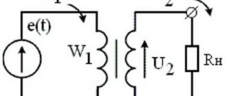
Electrical equipment (transformers, capacitors, cables) operating under high voltage will quickly break down and fail if they are not filled with operating oil. Its main purpose is to insulate current-carrying windings. Also liquid:
- cools;
- extinguishes the arc.
Winding - plays a protective function in the transformer. The surrounding oil in the reservoir protects against wear and failure. Due to convection, it rises up the tank pipe, cools and falls down again. This circulates constantly as it heats up.
Reference! The oil in the reservoir extinguishes the flashing arc in the event of a winding breakdown. This is a permanent dielectric that muffles the noise of the transformer and reduces the degree of vibration. It is only thanks to the oil medium that the electric charge does not spread.
Electrical transformers
In electrical type transformers, oil is used as a dielectric and biodegradable non-toxic fuel, therefore:
- removes heat;
- provides insulation between windings;
- prevents short circuits and failure of transformers;
- cools the installation;
- will not damage the ozone layer;
- will provide impeccable heat transfer and dielectric strength to the transformer;
- will prevent arcing in the switches.
The note! If the power of the power transformer is 50-500 kVA, then oil-paper insulation (oil-impregnated insulating paper) is used. When the unit power is 20-30 kVA, welded steel structures in the form of a tubular tank are used, where the magnetic core with windings is placed. Heat transfer is created between them and the oil with a good thermal conductivity coefficient and a high boiling point. The working fluid does not conduct electricity and will not allow a short circuit in the system.
Contact groups of switches
Switches at high-voltage substations supply electricity to cities and industrial enterprises. Their dimensions are comparable to a small house with voltage - 200-300,000 W, current up to 50,000 A.
Oil in switches serves:
- isolation;
- electronic arc extinguisher.
If an electric arc occurs when the contacts close, the situation will lead to their destruction in just a few cycles. If fresh oil is poured inside the transformer, sparking simply will not occur.
Application area of transformer oil
First, let's dispel some stereotypes. There is a persistent misconception that all liquids are conductors. In fact, not all, and not as obvious as metals.
An important property of transformer oil is its high resistance to electric current. So high that the liquid is actually a dielectric (within reasonable limits, of course).
Such a characteristic as lubricity is the least interesting in electrical engineering. But thermal conductivity, on the contrary, is very important.
We’ll talk about the properties separately; they stem from two areas of application:
- In electrical transformers, oil acts as a dielectric and a means for effective heat removal. Everyone knows that electrical installations get very hot. Air cooling is not so effective because it cannot ensure close contact of the cooled object with the heat removal medium. Transformers have to be made massive, with a large dispersion area. The purpose of transformer oil is to effectively remove heat in a relatively compact design. Radiators are present and even equipped with fans.
But such a heat removal system is not comparable in size to air-cooled transformers (in favor of liquid ones). - In addition, transformer oil is used in contact groups of switches. Of course, we are not talking about those keys on the wall that you use to turn on the light in the bathroom. Oil switches reach the size of a small house and are used at high-voltage substations that supply electricity to at least an industrial enterprise or an entire city.
Composition and properties
Transformer oil is a mineral liquid dielectric with a complex structure and formula. Includes:
- paraffins, cycloparaffins;
- hydrocarbon molecules;
- asphalt resinous components;
- sulfur, nitrogen compounds;
- naphthenic acids;
- antioxidant supplements.
The properties of the oil depend entirely on the grade and parameters of the original oil fraction. Basic:
- mobility under operating conditions at a pour point of -45 degrees and below;
- no ignition at flash point (+90+150gr);
- inability to oxidize, although inhibited transformer oil can oxidize under the influence of peroxide radicals;
- non-toxic, inability to harm the ozone layer;
- viscosity, although normally it should not be too viscous (28 to 30 mm2/s at t+20 degrees);
- thermal conductivity (0.09 to 0.14 W/(m×K));
- dielectric constant (2.1 to 2.4).
Reference! The properties of the oil can be distorted by exposure to high temperatures, contact with air, sunlight and short circuit currents. The influence of these factors must not be allowed, otherwise the acidity will increase and the electrical strength of the equipment will decrease in the event of destruction of the insulating winding.
The properties of the oil are directly affected by the dielectric loss tangent, therefore the presence of water fibers, liquids, and mechanical impurities in the oil is unacceptable. The freshness level of petroleum insulating oil for circuit breakers and transformers must meet international standards. If non-hydrocarbon inclusions are completely removed from the petroleum distillate during purification, then as a result of inhibition by ionol, the stability of the transformer oil will increase significantly.
Basic properties of oil in the heating system
The properties of transformer oil are divided into groups.
- Physical. The weight of the material should be less than the weight of the ice. The flash point of the oil must be high, otherwise it may ignite under heavy equipment load.
- Electrical. The transformer will work long and well when the oil has high dielectric strength, but over time it becomes less, fibers and water appear. The electrical properties of transformer oil are calculated through the dielectric loss tangent formula.
- Viscosity and stability.
An oil analysis will allow you to determine the wear of parts of the unit.
The technical characteristics of the oil are as follows:
- it is flammable;
- contains a minimum amount of toxic substances;
- biodegradable, does not have a harmful effect on the ozone layer of the earth;
- density of transformer oil - (0.84-0.89) × 103 kg/m³;
- kinematic viscosity at 20 °C - (28-30) × 10-6 m²/s.
The composition of the material must be constantly monitored so that it does not change during operation of the transformer. There is a method by which you can determine the level of compounds (gases) in a material, this is the analysis of transformer oil. With the help of such an analysis, it is possible to identify all equipment defects, the nature and extent of damage.
The condition of the transformer can be assessed by comparing data from the analysis with gas concentration values, as well as by the rate of increase in their level. Analysis of transformer oil and other types of lubricants allows us to determine the wear of equipment parts, its reliability and insulation.
Many damages inside are not visible, such as partial discharges, overheating, and sparking in contacts. All of them change the properties and composition of the oil, so chromatographic analysis should be carried out every six months for transformers with a voltage of 110 kV.
Level determination, maintenance and replacement of oil in transformers
The operation of transformers, with the exception of dry systems, is impossible without transformer oil. This working fluid plays an important role in the operation of transformer units. It performs two key functions - winding insulation and efficient cooling.
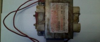
Example of a transformer that uses oil
In order for the oil to effectively perform its listed functions, it is important that it meets optimal operating parameters, which can vary depending on the ambient temperature, as well as its production. The first factor is taken into account during the production process and is offset by the fact that the composition of the transformer oil is selected so as to allow it to maintain optimal parameters over a wide temperature range. The second factor is related to the natural “aging” of the oil, which is associated with its long-term use. The main reasons that lead to wear of transformer oil will be listed below.
Causes of wear and aging of oil in a transformer
During operation of the transformer, its working fluid becomes oxidized, contaminated and moistened. This causes it to lose its optimal electrical and chemical properties. Aging products that are deposited on the active elements of the transformer system lead to poorer heat dissipation and overheating of both the oil itself and the transformer.
The main factors of oil aging are exposure to oxygen and electric fields. The catalyst for the aging process will be elevated temperature, the presence of various metal salts in the oil, exposure to direct sunlight and moisture.
An important factor in oil contamination is the shrinkage process of insulating materials. The destruction of the varnishes and cellulose materials used leads to the accumulation of dirt and its deposition on working surfaces. This contributes to worse heat dissipation and an increase in the operating temperature of the oil, and this, in turn, contributes to oxidation processes.
To prevent transformer failure, you should monitor the condition of its oil and carry out timely maintenance. After all, timely regeneration of the oil will completely restore its optimal properties.
Types of transformer repairs related to the quality of its oil
In order to determine the quality of the oil and its technical properties, samples are taken from the transformer. After laboratory tests on the chemical composition, an electrical density test is performed. Based on the results of such tests, a conclusion is made about which transformer repair method can be used in a particular case.
Change of oil
This procedure is carried out if the oil is heavily contaminated and technical parameters do not allow it to be used effectively. It is better to perform the procedure on the spot. During the replacement process, the transformer is dried from old oil and washed with special heated naphthenol or regenerated oil. This procedure allows you to completely remove from the transformer system all the dirt that has accumulated over years of operation. After this, regenerated or new oil is poured into the transformer. It is important to monitor its level in the transformer - it is important that it is neither higher nor lower than normal. To control it, special MS oil indicators are used. With their help, it will be possible to fill in exactly as much oil as needed for a specific type of transformer.
Changing the oil in the transformer
Oil regeneration
The regeneration process is a procedure for restoring oil parameters associated with the removal of aging products from its composition. This process can be carried out on site by pumping the oil from the bottom of the transformer, passing it through a regeneration unit and pumping it through an expansion tank. During the pumping process, the oil is passed through a special adsorbent, which precipitates aging products. In addition, it is amenable to dehydration, degassing and mechanical filtration. This procedure is continued until the desired operating parameters are achieved again.
Installation diagram for oil regeneration in transformers
Cleaning and drying
This procedure consists of separating mechanical impurities and existing moisture from the oil. This process is carried out by centrifugation and filtration through special paper filters. High cleaning performance can be achieved by using a centrifuge in conjunction with a filter press. This technique is widely used for cleaning working oil in transformers operating with voltages up to 110 kV. For devices operating with voltages from 220 kV, in parallel with the drying and filtration processes, oil degassing and, in some cases, saturation with inert gas are also used.
Diagram of an oil drying device
Oil aging protection
The methods for restoring oil parameters for its further operation were listed above. In addition, there are also ways to minimize the aging process of oil. Let's look at the main ones.
Expansion tank
This structural element, in addition to allowing you to compensate for changes in oil volume during temperature changes in the external environment, also allows you to minimize its contact with air. This will reduce the entry of moisture and oxygen into the oil and reduce its oxidation rate.
Air purifying filters
These elements are installed on the lowering pipelines of the expanders. The presence of such elements will clean the incoming air from mechanical impurities and reduce contact of air with oil.
Air purifying filter diagram
Adsorption and thermosiphon filters
Such elements are used to implement the procedure for constant oil regeneration directly during the operation of the transformer. Such filters are installed in the cooling system. They contain a special sorbent that cleanses the oil during its operation.
Nitrogen protection
This type of protection allows you to protect the oil in the conservator from its contact with the atmospheric environment. The main element of protection is an elastic tank filled with nitrogen.
Diagram of a device for nitrogen protection
Technical characteristics of transformer oil
Just like mineral motor oil, transformer oil is produced by distilling prepared crude oil (refined) by boiling the raw material. After sublimation at a temperature of 300°C - 400°C, what remains is the so-called solar distillate.
Actually, this substance is the basis for producing transformer oil. During cleaning, the saturation of aromatic carbons and non-carbon compounds decreases. The result is increased product stability.
When sublimating and separating the distillate, physical and chemical processes can be controlled. By manipulating the basic raw materials and technology, it is possible to change the properties of transformer oil. They are determined by the resulting ratio of components:
Interestingly, this product is environmentally friendly. During its production, use and disposal, the impact on nature is no higher than that of the feedstock (crude oil). The composition does not include artificially synthesized additives.
Like oil, oil for transformers and switches is non-toxic (as far as petroleum products are concerned), does not destroy the ozone layer, and decomposes without a trace in the natural environment.
One of the important characteristics is the density of transformer oil. A typical value is in the range 0.82 – 0.89 * 10³ kg/m³. The numbers depend on the temperature: the operating range is 0°C – 120°C.
When heated, it decreases; this factor is taken into account when designing a radiator cooling system for transformers.
Since oils are relatively universal, this characteristic may vary depending on the needs of the customer. Transformer substations are located in various climatic zones, often in the Far North and Siberia.
Using transformer oil for heating
Used (technical oil) is oil (machine, transformer or motor) that has already been used. These products have exhausted their service life and lost their original qualities, and were eventually removed from working systems. This waste oil product (waste oil) is used as a lubricant and as a wood impregnation to protect against rotting. But most often it is used as an energy carrier for liquid fuel boilers for heating houses.
New modern water heating boilers can, if necessary, operate on different types of energy sources. The boiler equipment mechanism does not have a firebox compartment and there is no open flame; not a single element of the boiler gets very hot, which together ensures a high level of safety.
The advantages of such equipment using waste transformer oil are:
- low price of oil;
- high equipment productivity and the ability to heat small dachas and country houses;
- fire safety, since the mining is not highly flammable.
The disadvantages include:
- arrangement of a special place for the possibility of storing mining;
- presence of a separate boiler room;
- establish contacts with organizations for the possibility of permanent acquisition of used oil;
- There is currently no fully automated heating equipment available on the market.
Portable air-type generators are the most popular on the market. They are easy to operate, have a built-in filter, and a fuel injection system.
In addition to economic benefits, the state is interested in supporting the development of the market for the use of waste transformer oil. High-quality support on his part is due to global reasons:
- to improve the environment;
- stopping the uncontrolled discharge of waste into the soil and rivers.
Characteristics of transformer oil.
Due to the fact that the characteristics of transformer oil deteriorate during operation, its quality must be periodically checked. Such checks are usually carried out once every three years, with an abbreviated oil analysis.
The main characteristics of transformer oil are:
· Acid number
, determines the amount of potassium hydroxide (in milligrams) required to neutralize all free acids. The acid number characterizes the degree of aging (oxidation) of transformer oil.
· Water extract reaction
, characterizes the presence of insoluble acids and alkalis in the oil. In a transformer suitable for use, the reaction of the water extract should be neutral. Acids have a destructive effect on the materials from which the transformer is made (they cause corrosion of the transformer metal and destroy the insulation of its windings).
· Flash point
oil temperature should not be lower than the specified values in order to avoid ignition of the oil when the temperature rises caused by overloading the transformer. For conventional transformer oils, the flash point is in the range of 130-150 °C.
· Content of mechanical impurities
. Impurities appear as a result of the dissolution of paints, varnishes and insulation; in the form of coal that is formed by an electric arc. Mechanical impurities in the oil can be contained in the form of sediment or in a suspended state and cause overlap between elements isolated from each other and reduce the electrical strength of the oil.
· Electric strength
determined by the breakdown voltage of the transformer oil. The breakdown voltage of fresh dry oil must be at least 30 kV. A decrease in the breakdown voltage value indicates the presence of impurities in the oil (fibers, air, water, etc.)
· Dielectric loss tangent
characterizes the insulating properties of transformer oil (shows how good a dielectric the oil is). Contamination and aging of transformer oil during its operation leads to an increase in dielectric losses in the oil.
· Moisture content
in transformer oil characterizes the intensity of insulation aging under the influence of significant temperatures (i.e., it indicates systematic overloads of the transformer), and also indicates a violation of the transformer seal.
· Viscosity
characterizes the mobility of the oil and should be small in order for the oil to circulate well and remove heat.
· Oil pour point
. At low ambient temperatures, the viscosity of the oil increases and its circulation deteriorates, which leads to overheating and accelerated aging of the insulation, and can also lead to damage to the moving elements of the transformer structure (on-load tap-changer, oil pump). According to standards, the pour point of transformer oil should not be higher than – 45° C.
· Color
. Fresh oil is usually light yellow in color. During operation, the oil darkens and acquires a dark brown color. The color of the oil changes due to its heating and contamination with resins and sediments.
In addition to those listed, there are other characteristics of transformer oils: density, gas content, stability, auto-ignition temperature, etc.
3.Answer
Installation of open electrical wiring, carried out with flat wires APPR, APPV, PPV, is carried out in a certain technological sequence. First, they mark the installation locations of lamps, switches and sockets, electrical wiring lines, wire fastenings, i.e. points for driving nails, installing staples and places where wires pass through walls and ceilings, starting from a group panel with a gradual transition to individual rooms. The installation locations of lamps on the ceiling are marked depending on their number. If one lamp is installed in the center of the room, then its location is determined by pulling two cords crosswise from opposite corners. The point of their intersection on the floor is marked with chalk, then this point is transferred with a plumb line from a stepladder to the ceiling. If you need to install two lamps in a room on the ceiling, then mark a middle line on the floor and divide it into four equal parts. The markings are transferred to the ceiling. The lamps are installed from the wall at a distance of 1/4 of the length of the room. After determining the installation locations of the lamps on the wall and ceiling, a line of future electrical wiring is cut off using a cord. On the line, the points of attachment of the wire are marked, as well as the points of through holes for the passage of wires through walls and ceilings. Next, using the template, mark the installation locations of branch boxes, plug sockets and switches.
Tools, mechanisms and devices for punching work: a - bolt; b - furrow cutter; c - burik; g - electric jointing hammer with a set of working tools
If holes were not left in advance in brick, concrete and reinforced concrete foundations, they are made using electrical, pneumatic or pyrotechnic tools (Fig. 4.2). Wire passages through fireproof walls are made in rubber or polyvinyl chloride tubes, and through combustible walls - in sections of steel pipes, with insulating bushings on both ends. The tube in the hole is sealed with cement mortar. The insulating tube should protrude from the sleeve by 5-10 mm. Flat wires are supplied to the installation area in coils. Before laying, they are unwound, cut into lengths and straightened. To do this, one end of the wire is secured, and the wire itself is pulled through a special straightening device or a mitten worn on the hand. The wire should be pulled through very carefully so as not to damage the sheath. Straightening of flat wires can only be done at a temperature not lower than - 15° C.
Operations for preparing a flat wire before installation: a - connection; b - bending on an edge in the plane of the wall
After straightening and cutting the wires, they are wound into coils. The laying of wires begins with the branch box closest to the group panel. A dividing base is cut out at the ends of a 75 mm long wire. For a three-core wire, the jumper between the second and third cores is also cut (Fig. a). The wire is laid, starting from the box, along the entire straight section to the point where the route turns. In this case, the wire at the other end is temporarily fixed, carefully straightened, laid along the entire length of the section and finally secured along the entire length of the route. When laying flat wires with a dividing partition (except for APPR wires) on combustible bases, asbestos with a thickness of at least 3 mm is laid under them along the entire length with a protrusion from the edge of the wire of at least 10 mm. Flat wires with a dividing base are secured with nails, protecting the wires from damage. Plastic, rubber or ebonite washers should be placed under nail heads in damp, unheated rooms. Wires without a dividing base are fastened with staples using dowels or nails, with a distance between fastening points of no more than 400 mm. For flat wires with a dividing base, when bending them on an edge (when the route is turned 90°), the base is cut out at the point of bending at a length of 40-60 mm.
Universal pliers KU-1 and installation operations performed with their help: a - cutting the wire; b - d - removal of the jumper; d - removal of insulation; e - making rings
When cutting flat wires, KU-1 or MB-241 pliers are often used, with which you can cut the film, bite it out, remove insulation from the ends of the wires, strip the wires and bend the rings at the ends of the wires to connect them to the contact screw. The next electrical installation operations are the connection and branching of flat wires in branch boxes. These operations are performed by welding, crimping or soldering, followed by insulation with polyethylene caps or insulating tape. The wires in the circuits of plug sockets are connected directly to the contacts of the sockets. Laying unprotected wires on insulators is used in production and warehouse premises along walls, ceilings and the lower belt of trusses in dry, damp, damp and especially damp rooms, as well as outside. Parts and structures for fastening insulators and wires are manufactured in factories. Each structure is a metal base with insulators on which wires are secured with special holders. Supporting metal structures (traverses) are made for fastening to trusses and walls by welding, clamps for two-, three- and four-wire lines. Examples of electrical wiring on insulators: a - on trusses; b—on the walls; c - holders
As a rule, when installing electrical wiring on insulators, marking the electrical wiring is done in the same way as when wiring with flat wires. Insulators are installed with the “skirt” down for all methods of their fastening. Next, end insulators are installed at passages through walls and when wires pass from one adjacent wall to another. Hooks and anchors with insulators are secured with putty. Wire passages through walls and ceilings are made in insulating tubes terminated with bushings. One wire is placed in each tube. At the installation site or at the power plant, wires are prepared and laid along prepared routes, and the minimum distance from the wires to the surface of walls and ceilings must be at least 10 mm. Protect wire runs from mechanical damage at a height of at least 1.5 m from the floor or service area by covering them with angle steel or laying them in pipes. The wires are secured on pin insulators with galvanized wire, and on trolleybus insulators with intermediate and end holders. Electrical wiring made with insulated and protected wires and cables suspended from a steel cable with a diameter of 3-8 mm or special AVT wires; AVTU; ABTV; AVTVU, which have their own supporting galvanized cable between three or four twisted cores, are called cable wiring.
Installation of cable wiring elements: a - anchor with tension sleeve; b - end seal of the cable using a thimble and die clamps; c - support cable; g - tension through bolt with hook; d— tension through bolt with ring; e - laying of insulated wires on cable hangers with wire plugs on nut-type insulators; g - grounding the APT wire cable using the free end of the loop
This type of electrical wiring is best for industrial installation. It is used in any environmental conditions, including hazardous areas of certain classes. When spans between cable hangers are 6 and 12 m, the cable sag should be 100-150 and 200-250 mm, respectively. In cable wiring, elements manufactured in factories are mainly used. The cables are attached to the end walls using through anchors or anchors attached to through pins, bolts or dowels. A loop is made at the end of the cable and a cable clamp and couplings are installed to adjust the tension of the cable. When wiring with cable wires, special branch boxes are used, which are simultaneously used for hanging the cable wire and lamps. Inside the box there is a device for fastening the cable. Branches are made without cutting the wire using clamps in a plastic casing. Cable wiring units are prepared at factories or at oil extraction plants on production lines and delivered to the installation site in containers. Cable branch box with hook for hanging lamps
Installation of electrical wiring with light cables with rubber and plastic insulation: a - methods of fastening the cable; b — device for turning at an angle of 90°; c - branching device with several cables laid in parallel
To install cable wiring, first mark the places of fastening of anchor and intermediate structures along the room along the line of location of lamps or power receivers, maintaining the distances between pendants, branch boxes and lamps according to the design and sketches of measurements at the installation site. Next, anchor and tension devices are attached to the main building elements (walls, trusses, etc.), hangers for intermediate fastenings are installed and they are attached to the lower chords of the trusses, columns, floors, in the cracks between the corners of the trusses or floor slabs. Then sections of the supporting cable, strings and guys are prepared, they are terminated with loops using sleeves and clips, the end fastening is assembled and measured sections of wires are prepared for the electrical wiring lines and the supply line (according to drawings or measurement sketches). After this, the wires are inserted into the boxes, the ends of the wires are connected in boxes or clamps, they are attached to the cable (for unprotected wires) with strips after 0.3-0.35 m, with perforated polyvinyl chloride tape after 0.5 m, with pendants after 1.5 m with plastic clips for two or four wires and clips for hanging lamps. When using protected wires, fastening with strips is carried out every 0.5 m. The strips are soft spacers and should protrude 1.5-2 mm on both sides of the cable. Next, the wires are called and labeled. If special wires are used for cable wiring, then input and branching are carried out using compressions U245 and U246 without cutting the phase wires. To lay the prepared lines, the wires are unwound on the floor using special crosses and raised to a height of 1.3-1.5 m to straighten and hang the lamps. Next, the wires are raised to the design height and one end of the cable is secured to the anchor structure. Connect the line with previously installed intermediate hangers and guy wires. Adjust the sag and put the cable on the opposite anchor device. In places where exposed sections of the cable and the anchor device come into contact, they are lubricated with Vaseline. The cable at the end of the line is grounded at two points by connecting copper jumpers with a cross section of 2.5 mm2 to the neutral wire or bus connected to the ground loop. The support cable cannot be used as a grounding conductor. Next, use a megohmmeter for voltages up to 1000 V to measure the insulation resistance of the electrical wiring. It must be at least 0.5 MOhm. Electrical wiring with unarmored protected wires and cables with a cross-section of up to 16 mm2 with rubber and plastic insulation is laid directly on the surface of the walls. Such electrical wiring is secured with staples, buckles (Fig. 4.8) or on strips, tapes and strings (Fig. 4.9), which sharply reduces the labor intensity of hole-punching work. Assembly perforated strips and tapes with a width of 16 and a thickness of 0.8 mm; cold- or hot-rolled tape with a width of 20-30 and a thickness of 1-1.5 mm are used as load-bearing structures. Tapes and strips are attached directly to the base with a distance between the attachment points of 0.8-1 m, and from the end of the strip - no more than 70 mm. Galvanized wire with a diameter of 3-4 mm, stretched close to the base and secured at the ends with tension devices, is used as a supporting string. Protected wires APRF (PRF, PRFl) are straightened on a workbench or manually. Laying cables and wires along the wall with fastening to the strings: a - U954 suspension; b — U957 suspension; c - Loskutov strip; d - K226 tape; d— stripe with PI buckle; e, i - PL strip with a buckle; g— strip 20 x 1 with a “mustache”; h, j - mounting strip K-200 Wires and cables are secured with metal or plastic bands at a distance of 10-15 mm from the bending points of the route and 100 mm from their entry into the branch boxes. The distance between fastening points is 500 mm. Bearing strips, tapes and strings are grounded in the same way as cable wiring. The metal sheaths of the APRF, PRF, PRFl wires are grounded at the supply panels or points with a flexible copper jumper soldered to the metal sheath of the cable or wire.
Ticket 8
Answer
Range of transformer oils
The following brands of transformer oils are produced on the territory of the Russian Federation[6]:
- GK II A
- used in electrical equipment of all voltage classes; - VK II A
- the same; - MVT III A
- low-oil switches; - T-1500 U II A
- electrical equipment with voltage up to 500 kV inclusive; - TKp II A
- the same; - selectively purified oil
- electrical equipment with voltage up to 200 kV inclusive; - GK III A
- the same.
Mechanism of flash and ignition
In a flash, the oil simply ignites due to high temperatures and exposure to a fire source. Flash is detected by applying the lowest temperature. When diagnosing, specialists calculate:
- how does a flash affect oil volatility;
- how many volatile hydrocarbons are contained, because the more there are, the lower the flash t.
Important! If flash t is low. This means that there are defects in the equipment that provoke the formation of flammable volatile fractions. To avoid fire and combustion in the transformer, the ignition temperature must be higher than the operating temperature of the unit. If the flash is 180 degrees, then the ignition should be at least 150.
As transformer oil ages, it burns continuously, unless, of course, the steam-air mixture ignites after bringing a match to the flame after 5-6 seconds. The ignition temperature is determined after a flash is detected. The fact is that lubricating oil begins to evaporate when the flash point of the oil is 60-70 degrees below the ignition temperature.
Flash point of transformer oil
This characteristic represents the minimum temperature value at which the vaporization process begins.
The main functions of transformer oil are insulation and cooling of the transformer. This oil is stable at high temperatures and has excellent electrical insulating properties. That is why such oils are used in transformers to insulate live parts under high voltage and cool them.
No load or wasted load tends to increase the temperature of the transformer winding and the insulation around the winding. An increase in oil temperature occurs due to heat removal from the windings.
If the flash point of the oil is below the standard value, the oil product evaporates, forming hydrocarbon gases inside the transformer tank. In this case, the Buchholz gas relay is usually activated. It is a protective device that is installed in many power electrical transformer designs where an external oil reservoir is provided.
The usual flash point range for transformer oils is 135….145°C.
How to check
Indicators by which oil is checked for freshness:
- Moisture and gas content. It is measured due to the reaction of moisture that may be in the oil when interacting with oxygen hydride. Gases are calculated by changing the residual pressure in a tank filled with oil.
- The amount of mechanical impurities.
- Electrical strength.
- Loss tangent. In fresh oil it does not exceed 0.02%, in oxidized oil it does not exceed 0.2%.
Transformer oil operating instructions
During operation of a leaky oil transformer, the oil level decreases over time: some evaporates, some goes to sampling for quality control. Therefore, add oil periodically.
Important! Sometimes, when fresh oil is mixed with used oil, the quality of the latter deteriorates. Therefore, mix oil only after laboratory confirmation
Operating oil in cold climates
In cold conditions, oil performance is greatly affected by its pour point. The lower the temperature drops, the thicker the oil becomes. If it is thick, it circulates less well in the tank, and therefore cools the transformer less well. Standards for oil freezing temperature at an ambient temperature not lower than minus 20 °C - minus 35 °C for an oil switch and minus 45 °C for a transformer. For other areas, the pour point of the oil should not be higher than minus 45 °C.
We take oil samples
- Take oil for analysis only in dry weather to prevent damp air from entering the tank.
- Mark the sample with the date and location of collection.
- Deliver the oil for analysis within 7 days.
Slow down oil aging
Install a thermosiphon filter. The oil will then be continuously reduced as it passes through the silica gel in the filter. The advantage of this method is that regeneration occurs directly during operation of the transformer.
Often, a thermosiphon filter is supplemented with nitrogen protection - nitrogen is pumped into the tank and insulation instead of air. In this case, the oil practically stops oxidizing and moisturizing.
Add special anti-oxidation additives to the oil - VTI-1. This will significantly slow down the process of oil self-destruction.
In transformers with a leaky oil tank, the oil sooner or later loses its properties. In this case, you can restore it. There are several ways to restore transformer oil. We will tell you more about them in our next article.
We hope that our article will help you extend the life of your transformer oil. Let your energy system run like clockwork.
Density of used transformer oil
In the process of extinguishing possible electrical discharges that may occur inside the transformer housing, the oil becomes contaminated with tiny particles of electrical insulation, as well as products of chemical reactions. At high local temperatures they can occur in an oil environment. Therefore, over time, the density of the oil increases. This leads to a decrease in the cooling ability of the oil and the appearance of possible conduction bridges, which reduce the electrical safety of the transformer. This oil must be replaced. It is carried out after a certain number of hours of operation of the device, which is usually indicated by its manufacturer. However, when operating a transformer under extreme conditions, the need for replacement may arise earlier.
For paraffin-based products, the increase in the density of transformer oil is also due to the fact that oxidation products (sludge) are insoluble and are deposited at the bottom of the tank. This sediment acts as an obstruction to the cooling system. In addition, the excess volume of high-molecular compounds increases the pour point of the oil.
Testing of actual density values is carried out in the following sequence:
- Oil samples are taken from different places in the container. The fact is that the destruction of the dielectric is inversely proportional to the water content in it, which means that the dielectric resistance of transformer oil decreases as the water content increases.
- Using a densitometer, the density of the oil is measured and compared with the recommended values.
- Depending on the number of hours the oil has been used in the transformer, either add the specified volume of new oil or carefully filter out the old one.
Nitrogen protection system
In addition to the above processes, a nitrogen protection system is used to prevent oil oxidation. However, it is worth noting that nitrogen protection does not work if the oxygen concentration in the oil exceeds permissible limits.
To slow down the destructive processes of acids and unwanted impurities, antioxidant inhibitor additives are often added to transformer oil.
Additives are divided into groups:
- antioxidant inhibitors - compounds that interrupt the chain oxidation process;
- metal deactivators - compounds that convert metal compounds dissolved in oil into an inactive form;
- metal passivators - compounds that promote the formation of a film on the metal surface, protecting the oil from the action of the metal;
Aging concept
Aging is an irreversible process in transformer oil, because as it is used, moisture and oxidation products get in one way or another. The operational, chemical, physical properties and heat transfer begin to decrease. The transformer stops working normally.
It is worth carrying out prevention and identifying defects by taking oil samples for analysis.
The properties of the oil are restored through drying, regeneration, and cleaning.
Causes of aging:
- increased acidity;
- formation of sediment on the windings of the transformer;
- deterioration of electrical insulating properties;
- oxidation is an induction process at the initial stage.
Stable oxidation products accumulate in the oil: organic peroxides, water, low molecular weight acids. Gradually the working fluid darkens and becomes cloudy. The ash content and acid number increase. Solid polymerization products begin to float on the surface, clogging the cooling channels of the transformer.
Chromatographic analysis
One of the components of a complete analysis of transformer oil is chromatographic analysis of gases dissolved in the oil, which has gained popularity in the oil technology market and is provided as a separate high-tech equipment for self-testing of oils at industrial enterprises.
This method is designed specifically for detecting damage and defects of individual structural units and, in general, of all solid insulation of electrical equipment. However, it does not provide virtually any information about the quality and condition of the oil itself.
Despite this, it allows you to monitor the development of processes in the transformer, anticipate damage that cannot be detected by traditional methods, characterize the damage and help you navigate when determining its location.
The chromatographic analysis itself takes about 30 minutes. The equipment complex consists of several (for a large amount and a complete list of oil analysis) or one chromatograph (for a small amount and an incomplete list of oil analysis), and includes auxiliary equipment along with consumables, with the help of which it solves all the problems listed above.
Options for using transformer oil in everyday life
The liquid is used not only on industrial equipment and power transformers, but also in everyday life:
- for cooling, extinguishing electric arc;
- pouring into electrical equipment of high voltage classes;
- lubrication of vacuum switches, high-voltage transformers.
The service life of the transformer and oil are not directly related to each other. However, a high-voltage installation will last trouble-free for up to 15 years if the oil is cleaned annually and regenerated once every five years, antioxidants are removed, filtered, antioxidant additives and expanders are installed with filters for removing gases and absorbing water and oxygen.