We can recall many cases when a converter from 12 volts DC to 220 volts AC would be useful - for example, when you arrive at your dacha by car, you can turn on the lights in the evening or power a watering pump from a battery.
Also, such an inverter is an integral part of wind generators. Buying a ready-made device will not be a problem - and in auto stores you can find car inverters (pulse voltage converters) of various powers and prices.
However, the price of such a medium-power device (300-500 W) is several thousand rubles, and the reliability of many Chinese inverters is quite controversial. Making a simple converter with your own hands is not only a way to significantly save money, but also an opportunity to improve your knowledge in electronics. In case of failure, repairing a homemade circuit will be much easier.
Common Schemes
Simple pulse converter
The circuitry of this device is very simple , and most of the parts can be removed from an unnecessary computer power supply. Of course, it also has a noticeable drawback - the 220 volt voltage obtained at the output of the transformer is far from sinusoidal in shape and has a frequency significantly higher than the accepted 50 Hz. Electric motors or sensitive electronics must not be connected directly to it.
In order to be able to connect equipment containing switching power supplies (for example, a laptop power supply) to this inverter, an interesting solution was used - a rectifier with smoothing capacitors is installed at the output of the transformer . True, the connected adapter can only work in one position of the socket, when the polarity of the output voltage coincides with the direction of the rectifier built into the adapter. Simple consumers such as incandescent lamps or a soldering iron can be connected directly to the output of transformer TR1.
The basis of the above circuit is the TL494 PWM controller, the most common in such devices. The operating frequency of the converter is set by resistor R1 and capacitor C2; their values can be taken slightly different from those indicated without noticeable changes in the operation of the circuit.
For greater efficiency, the converter circuit includes two arms on power field-effect transistors Q1 and Q2. These transistors should be placed on aluminum radiators; if you intend to use a common radiator, install the transistors through insulating spacers. Instead of the IRFZ44 indicated in the diagram, you can use IRFZ46 or IRFZ48 that are similar in parameters.
Higher power device circuits
Converter up to 400 W
The circuit consists of a master oscillator (chip A1 - KR1211EU1, has no foreign analogue - it is a master oscillator with two outputs: direct and inverse, 4 and 6, respectively), two switches (field switches VT1 and VT2), transformer T1 (step-up).
Pin 1, when a high signal level is applied to it, stops the generator; it is not used in this implementation; in the circuit a constant low level signal is supplied to it.
The generation frequency is determined by R1 – C1, reliable starting of the generator is ensured by R2 – C2. The stabilizer (elements R3, VD1, C3, stabilization 8-10 V) powers the microcircuit.
The output is a push-pull cascade: two powerful field-effect transistors IRL2505 (for loads up to 200 W, radiators are not required, if a large load is possible, radiators are required).
The transformer can be any kind of network transformer with two windings for 12 V of the required power, a toroidal one is better, another one is possible, but the following condition must be met: the power of the transformer must exceed the expected load by 2 (this is if the toroidal core is) - 2.5 times. Example: if the load is 100 W, the power needed is 250 W, if the load is toroidal - 200 W.
Capacitor C6 (it smoothes the pulse) can be K-73-17 or similar, with a voltage of 400 V or higher. When the power consumption is high, the current from 12 V can exceed 40 A, which is why you need to pay attention to the cross-section and length of the power bus.
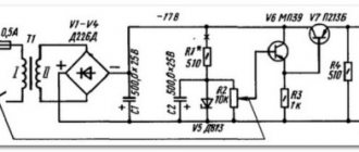
Powerful voltage converter from 12 V to 220 V
Designed for loads up to 1000 W, requiring 220V AC voltage. We used old P216 transistors, which radio amateurs can still find in their households.
Transistors VT1, VT2 and transformer T1 are used here as a master oscillator - the frequency is set to 200 Hz. The secondary winding T1 sends the signal through capacitors to the electrodes of thyristors VD1, VD2, which create a pulse voltage in the first winding of transformer T2.
The non-polar capacitor C4 (its capacitance) is selected so that its voltage alternately closes the thyristors. Resistor R3 protects 12 V circuits from overload when the thyristor opens.
For transformer T1:
- at the core - plate Ш16Х10;
- in winding 1 – 40+40 turns PEL 0.8;
- in winding 2 – 10+10 turns PEL 0.3;
- in winding 3 – 20+20 turns PEL 0.3.
In transformer T2:
- in the core – plate Ш50Х60;
- in winding 1 – 40+40 turns with wire 3 mm in diameter;
- in the winding 2 - 460 turns, PEL wire 0.8.
The use of KU202 thyristors will make it possible to assemble a similar converter of lower power.
You can also use new silicon transistors, in which case an adjustment to the constant current mode is required.
Improvements to inverter circuits
The devices presented in the article are extremely simple and in a number of functions cannot be compared with factory analogues . To improve their characteristics, you can resort to simple modifications, which will also allow you to better understand the principles of operation of pulse converters.
Increased power output
All described devices operate on the same principle: through a key element (arm output transistor), the primary winding of the transformer is connected to the power input for a time specified by the frequency and duty cycle of the master oscillator. In this case, magnetic field pulses are generated, exciting common-mode pulses in the secondary winding of the transformer with a voltage equal to the voltage in the primary winding multiplied by the ratio of the number of turns in the windings.
Therefore, the current flowing through the output transistor is equal to the load current multiplied by the inverse turns ratio (transformation ratio). It is the maximum current that the transistor can pass through itself that determines the maximum power of the converter.
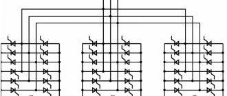
There are two ways to increase the power of the inverter: either use a more powerful transistor, or use parallel connection of several less powerful transistors in one arm. For a homemade converter, the second method is preferable, since it not only allows you to use cheaper parts, but also preserves the functionality of the converter if one of the transistors fails. In the absence of built-in overload protection, such a solution will significantly increase the reliability of a homemade device. The heating of the transistors will also decrease when they operate at the same load.
Using the last diagram as an example, it will look like this:
Automatic shutdown when battery is low
The absence of a device in the converter circuit that automatically turns it off when the supply voltage drops critically can seriously let you down if you leave such an inverter connected to the car battery. Supplementing a homemade inverter with automatic control will be extremely useful.
DIY voltage converter from 12 to 220V 50Hz
In the vast expanses of our homeland, in cities and villages, there are often power outages, and no one is immune from this. Therefore, I propose to assemble a homemade voltage converter from 12 to 220V 50Hz, which will help you out in difficult times and will become an indispensable assistant wherever you are: in the forest, at the dacha, at home, fishing.
This figure shows the circuit of a simple voltage converter from 12 to 220V with an operating frequency of 50Hz.
Voltage converter circuit from 12 to 220V 50Hz
The circuit is based on the good old symmetrical multivibrator on two bipolar transistors T2 and T3, which controls powerful switches on field-effect transistors T4, T5, T6 and T7. Rectangular pulses taken from the multivibrator alternately open the field-effect transistors and thereby pump up the transformer, which converts the incoming 12V DC voltage into 220V AC voltage. The operating frequency of the multivibrator is 50 Hz. The frequency adjustment of the multivibrator can be done by eye using the trimmer resistor P2, for example, compare the hum of the plates of the output transformer of the voltage converter with an ordinary network transformer connected to the network, or using an oscilloscope. How I did it.
Protection against battery discharge is assembled on transistor T1 and relay Rel1. The minimum protection response voltage is set by trimming resistor P1. How does the protection work? When the voltage is more than 12V, the current flows through the open transistor T1 to the relay winding Rel1. The relay contacts close and the multivibrator turns on, the green LED signals that the voltage converter is turned on. When the battery discharges below 10V, the transistor closes, the relay contacts open, the multivibrator turns off and the red LED lights up.
This figure shows a printed circuit board for a voltage converter from 12 to 220V 50Hz.
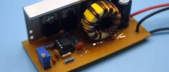
Printed circuit board voltage converter from 12 to 220V 50Hz
The voltage converter is assembled on a printed circuit board measuring 70x100 mm. Bipolar transistors of npn structure T2 and T3 can be installed in almost any KT815, BD139, KT805, KT819, TIP41, MJE13007, MJE13009 and many others.
The circuit can drive up to four pairs of powerful field-effect transistors IRFZ40/44/46/48, IRF3205, IRL3705/IRF3808 and other N-channel field-effect transistors. During operation of the device, the transistors remain cold, so there is no need to install a radiator. The power of the converter directly depends on the dimensions of the transformer. From a transformer with an overall power of 100 W, it is impossible to remove more than 100 W. At idle, the voltage converter consumes from 0.15A to 1A, it all depends on the power of the transformer.
Which transformer is suitable for a voltage converter?
The circuit contains an ordinary mains transformer with an iron core. The primary network winding of the transformer is 220V, and two secondary windings of 15V are connected in series and have a common midpoint. The ideal option is, of course, to use a toroidal transformer from a stereo system; such transformers are more compact in size and have slightly increased efficiency. The primary winding of the transformer will become the output winding, 220V will come out of it, and the secondary winding is connected to the multivibrator according to the diagram.
If you have a regular transformer, for example from a tube TV, then the secondary winding must be rewound. To do this, you will need a copper wire in varnish or PVC insulation. The secondary winding is wound in two wires and contains only 30 turns; at the rate of two turns per volt, the result is two windings of 15 volts. The end of the first winding is connected to the beginning of the second; this will be the middle point.
The output power of the converter depends on the size of the transformer. There are special formulas for calculating a transformer for a voltage converter, but all this is very complicated and problematic. As practice has shown, the thicker the wire is wound in the secondary winding, the higher the efficiency of the voltage converter. But the size of the transformer window does not always allow for winding a thick wire. Therefore, there must be a golden mean, the diameter of the secondary winding wire should be twice the diameter of the wire with which the primary winding is wound.
For example, you have a transformer in which the primary network winding is wound with a copper wire with a diameter of 0.5 mm, then we wind the secondary winding with a wire with a diameter of 1 mm, it will not be possible to wind a thicker wire, the limited space of the transformer window will not allow this.
The power of the converter I assembled is 100 W, operating frequency is 50 Hz. Output voltage 220V.
You can connect almost any low-power device, LED lamp, laptop, fan, screwdriver, TV, electric razor to this device.
Radio components for assembly
- Foil textolite 70x100 mm
- Capacitors C1 1000 µF 25V, C2, C3 4.7 µF 50V
- Resistors P1 10 kOhm, P2 1 kOhm, R1 10 kOhm, R2, R3 1 kOhm, R4, R7 680 Ohm, R5, R6 2.2 kOhm, R8-R11 10 Ohm
- LEDs Red, Green operating voltage 3V
- Voltage stabilizer L7809CV
- Relay SRD-12VDC-SL-C
- Transistors T1 BD139, T2, T3 KT815, BD139, KT805, KT819, TIP41, MJE13007, MJE13009 and other npn structures. T4-T7 IRFZ40/44/46/48, IRF3205, IRL3705/ IRF3808 and other N-channel field-effect transistors
Friends, I wish you good luck and good mood! See you in new articles!
I recommend watching a video about how a voltage converter works from 12 to 220V 50Hz
Inverter fault detection
The listed simple circuits have the two most common faults - either there is no voltage at the transformer output, or it is too low.
- The first case is either a simultaneous failure of both arms of the converter, which is unlikely, or a failure of the PWM generator. To check, use an LED probe, which can be purchased at any radio parts store. If PWM is working, you will see the presence of a signal at the gates of the transistors by the rapid pulsations of the diode glow (this is especially noticeable in low-frequency circuits). If there is a control signal, check for breaks in the connections of the transformer and the integrity of its winding.
- A large voltage drop is a clear sign of failure of one of the inverter's power arms. You can find a failed transistor in the simplest way - its radiator will remain cold. Replacing the key will restore the inverter's functionality.