According to the Electrical Installation Rules, any electrical networks and equipment operating with voltages above 50 volts AC and 120 volts DC must have protective grounding. This applies to premises without signs of high-risk conditions. In hazardous areas (high humidity, conductive dust, etc.), the requirements are even stricter. But in this material we will mainly consider residential buildings. By default, we assume that there must be grounding.
When installing new power supply lines, grounding will be installed, and the owner of the premises can monitor this (or connect it himself). In the case when you live (work) in a ready-made room, the question arises: how to check the grounding? First of all, you need to make sure that you have it. Regardless of formal compliance with the EIC, this concerns the life and health of people.
Checking the presence and correct connection of protective grounding
At a minimum, you need to look into the switchboard of your apartment (house, workshop).
By default, we accept the condition: single-phase power supply. This will make it easier to understand the material.
The panel must have three independent input lines:
- Phase (usually indicated by a wire with brown insulation). Identified by an indicator screwdriver.
- Working zero (color marking - blue or cyan).
- Protective grounding (yellow-green insulation).
If the power supply input is designed this way, you most likely have a ground connection. Next, we check the independence of the working zero and protective grounding from each other. Unfortunately, some electricians (even in professional teams) use so-called grounding instead of grounding. The working zero is used as protection: a grounding bus is simply connected to it. This is a violation of the Electrical Installation Rules; using such a circuit is dangerous.
How to check whether grounding or grounding is connected as protection?
If the connection of the wires is obvious, there is no protective grounding: you have grounding. However, the apparent correct connection does not mean that there is a “ground” and that it is working. Checking grounding includes several stages. We start by measuring the voltage between the protective ground and the working zero.
We fix the value between zero and phase, and immediately carry out a measurement between the phase and protective grounding. If the values are the same, the “ground” bus has contact with the working zero after physical grounding. That is, it is connected to the zero bus. This is prohibited by the PUE; the connection system will need to be altered. If the readings differ from each other, you have the correct “ground”.
Further grounding measurements are carried out using special equipment. Let's look at this in more detail.
How does grounding work and why check its parameters?
Without going into details, we can say that grounding is needed to connect the electrical installation housing to the working zero. Looking at a few paragraphs above, you might think that this is absurd. In fact, what is meant is the possibility of current flowing from the protective grounding, through the physical ground (soil), to the working zero of the nearest substation. In fact, it will be a short circuit.
Accordingly, when a phase gets on the body of the electrical installation, the circuit breaker will operate, and there will be no electric shock.
Why is it necessary to check grounding resistance? To organize an emergency short circuit, a large current is required. If the resistance of the ground loop is too high, the current strength (in accordance with Ohm's law) will decrease and the circuit breaker will not operate.
Another danger of high resistance of the protective “earth” is that the resistance of the human body may be less. Then, if you touch an emergency electrical installation with your hand, you are guaranteed to be shocked by an electric shock.
Important! Grounding itself does not provide 100% protection against electric shock.
When a phase appears on the body of the electrical installation, part of the voltage will go to compensate for the leakage into the physical ground. If the remaining potential exceeds 50 volts, the danger will remain.
Likewise, a circuit breaker without grounding will not disconnect a phase if it hits the housing. It will only work when the zero is connected to the phase. Complete protection is provided by installing the machine and simultaneously connecting the protective ground circuit. The RCD also significantly increases the level of safety.
And finally, about what a ground loop is.
In short, these are several metal pins (under normal natural conditions - three), deeply immersed in the ground, connected by conductors to each other and the grounding bus in the building.
In a private house
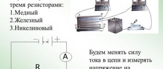
To check the quality of grounding, people who live in private houses will need a special measuring device, known under the factory designation M416. Using this device, you can quickly and accurately measure the resistivity value of pins driven into the ground and the adjacent soil layers.
However, before checking the resistance of the charger in a private house using the M416, it is advisable to have at least an approximate idea of how this device works.
The operating principle of the ground resistance meter is based on the compensation method of taking readings. The method is implemented using an auxiliary pin and a set of metal electrodes (probes).
To measure the resistance of protective grounding, an additional pin and an external probe from the kit are driven into the ground at some distance from the structure under test (in the figure it is designated as a “ground electrode”). After this, the corresponding terminals of the device are connected to them using cords of various markings.
As a result, a measuring circuit is formed, through which, after pressing the start button on the control panel, the value of the desired quantity is determined based on the indicator reading.
You should study in detail how to operate the M416 device in order to check the grounding resistance correctly and as quickly as possible.
If the user is not confident in his abilities or for some reason cannot carry out measurements on his own, then he will have to invite a specialist and pay according to the tariff for all work included in the grounding check.
Checking protective grounding parameters
In addition to the obvious components of the protective “earth” system: such as a contact block, wires going to electrical installations, connection to a circuit in the ground, the earth itself plays an important role in providing protection. Accordingly, you need to make sure of the following:
- Between all elements of the circuit (pins, connecting bars, conductor into the room to the terminal block) there is a reliable electrical connection with minimal resistance.
- The voltage applied to the circuit (in the event of an accident) spreads across the physical ground with maximum current. This is only possible with good contact between the metal and the ground.
- The physical conditions of the terrain (ground) can ensure reliable contact even under poor (in terms of electrical current) conditions. Namely, drying out of the soil, cracking of the earth in the places where ground electrodes are installed.
Of course, no one takes measurements of parameters on every element of the grounding system. This will be required only in case of non-compliance with the standards, to find the so-called “weak link”.
By what principle is the protective ground loop checked?
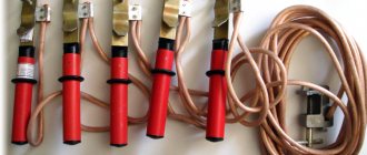
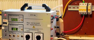
It is necessary to create a complete analogue of a circuit that is known to work, and compare the indicators with the tested object. For this purpose, there are complexes for testing working grounding.
Let’s make a reservation right away: it is possible to make such a kit yourself, but it is expensive and impractical. Likewise, checking the parameters of protective grounding using standard measuring instruments (multimeter) will not show a reliable picture. And the tester will not be able to generate the high voltage necessary to measure spreading parameters. Therefore, it is better to either rent equipment or invite a specialist.
You can buy a set like this, but it is unlikely to pay for itself in the foreseeable future. Even taking into account that the frequency of checking grounding devices is once a year (for both residential and industrial facilities), it is easier to get one-time access to the equipment.
Checking the circuit between grounded elements
To protect against electric shock when touching exposed conductive parts that become energized when the insulation is damaged, protective measures must be taken. Such protection measures include: Protective grounding - a deliberate electrical connection of any point in the electrical network, electrical installation or equipment with a grounding device, made for electrical safety purposes above 1 kV and up to 1 kV with an isolated neutral (IT system) and a grounded neutral (TT system ). Protective automatic power off - automatic opening of one circuit of one or more phase conductors (and, if required, the neutral working conductor), performed for electrical safety purposes - in electrical installations up to 1 kV, in which connection of all open conductive parts to the grounding device is performed, if IT or TT is applied, and to the solidly grounded neutral of a generator or transformer in three-phase networks, with a solidly grounded output of a single-phase source, with a grounded source point in DC networks, if T1Ch is used, and the main and additional potential equalization systems are installed.
The cost of checking the presence of a circuit between grounding conductors and grounded elements for one point up to 1000V starts from 15 rubles, up to 10 kV - from 50 rubles, and up to 35 kV - 55 rubles
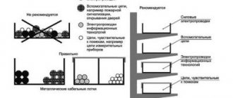
Connections and connections of grounding and protective conductors to grounding conductors, to exposed conductive parts and third-party conductive parts must be reliable and ensure the continuity of the electrical circuit, which is checked by measuring the presence of a circuit between the grounding conductors and the grounded elements, and the reliability of detachable contact connections by measuring the transition resistance between the grounded installation and the grounded elements. its elements. It is recommended to make connections of steel conductors by welding. It is allowed to connect grounding and neutral protective conductors in indoor and outdoor installations without aggressive environments in other ways that meet the requirements of GOST 10434 “Electrical contact connections. General technical requirements" for class 2 connections. Connections of grounding conductors to the grounding conductor and grounding structures must be made by welding, and to the main terminal, open conductive parts of electrical installations and overhead line supports - by bolting (to ensure the possibility of taking measurements). Connections to equipment that is subject to frequent disassembly, or installed on moving parts or subject to shock or vibration, must be made using flexible conductors. Connections of protective conductors of electrical wiring and overhead lines should be made using the same methods as connections of phase conductors.
Connections must be protected from corrosion and mechanical damage; for bolted connections, measures must be taken to prevent contact loosening. Connections must be accessible for inspection and measurement, with the exception of connections filled with compound or sealed, as well as welded, soldered and pressed connections to heating elements in heating systems located in floors, walls, ceilings and in the ground.
Grounding and grounding lines, as well as branches from them in enclosed spaces and outdoor installations, must be accessible for inspection; the requirement for accessibility for inspection does not apply to neutral conductors and cable sheaths, to reinforcement of reinforced concrete structures, to protective conductors laid in pipes and ducts , as well as directly in the body of building structures.
The connection of each open conductive part of the electrical installation to the neutral protective or protective grounding conductor must be made using a separate conductor. Series connection of exposed conductive parts with grounding and protective conductors is not allowed.
In places where damage to the insulation of phase conductors is possible as a result of sparking between an uninsulated neutral protective conductor and a metal shell or structure (for example, when laying wires in pipes, boxes, trays), the neutral protective conductors must have insulation equivalent to that of the phase conductors. Uninsulated neutral protective conductors must be protected from corrosion. Openly laid protective grounding conductors must be protected from corrosion, chemical influences and painted black. The smallest cross-sections of protective grounding and neutral protective conductors in electrical installations up to 1000V are indicated in the table. The cross-sectional areas are given for the case when the protective conductors are made of the same material as the phase conductors. The cross-sections of protective conductors made of other materials must be equivalent in conductivity to those given.
The cross-sections of protective conductors must correspond to the values indicated in the table:
| Cross-section of phase conductors, mm2 | Smallest cross-section of grounding and protective conductors, mm2 |
| 8<16 16<8<35 8>35 | 8 16 8/2 |
The cross-section of protective conductors that are not part of the cable or laid not in a common sheath (pipe, box, on one tray) in all cases must be at least: 2.5 mm copper - in the presence of mechanical protection; 4 mm2 copper - in the absence of mechanical protection; 16 mm2 aluminum.
In electrical installations with voltages above 1000 V, the cross-section of the grounding conductors must be selected in such a way that when the highest single-phase short-circuit current flows through them - with an effectively grounded neutral, or a two-phase short-circuit current - with an isolated neutral, the temperature of the grounding conductors does not exceed 400 ° C.
In electrical installations with voltages higher than 1 kV with an insulated neutral, the conductivity of grounding conductors with a cross-section of up to 25 mm2 for copper or equivalent from other materials must be at least 1/3 of the conductivity of phase conductors. As a rule, the use of grounding copper conductors with a cross-section exceeding:
- 25 mm2 copper;
- 35 mm2 aluminum;
- 120 mm steel.
The grounding conductor connecting the working (functional) grounding conductor to the main grounding bus in electrical installations with voltage up to 1 kV must have a cross-section of at least:
- 10 mm2 copper;
- 16 mm2 aluminum;
- 75 mm2 steel.
The cross-section of the protective conductors of the main potential equalization system must be at least half the largest cross-section of the protective conductor of the electrical installation, if it does not exceed 25 mm2 for copper or equivalent for other materials. The use of conductors of larger cross-sections is, as a rule, not required.
The cross-section of the conductors of the main potential equalization system must be at least: 6 mm copper; 16 mm2 aluminum; 50 mm2 steel.
The cross-section of the conductors of the additional potential equalization system must be no less than:
- when connecting two open conductive parts of the cross-section of the smaller of the protective conductors connected to the open conductive part;
- when connecting an open conductive part and a third-party conductive part - half
- cross-section of the protective conductor connected to the open conductive part;
- not included in the cable: at least 2.5 mm2 for copper - with mechanical protection;
- not less than 4 mm2 for copper - in the absence of mechanical protection;
- not less than 16 mm2 aluminum.
During a visual inspection, you should check the cross-sections, integrity and strength of protective conductors and contact connections. There should be no breaks or visible defects. Contact connections are checked by inspection and tapping, and detachable contact connections are also checked by measuring the transition resistance between grounding conductors and grounded elements, the grounded installation and installation elements. To check the presence of a circuit between the grounding electrode and the grounded elements, the grounded installation and the elements of the grounded installation, there are a number of devices that differ in the scope of application, ranges of measured values, circuits, noise immunity, frequency of the measuring current, etc.
Measurements are made by devices: F4104-M1; R.ZZZ; F4103-M1;MKI-100;M1SH-101;MKR-200;M2R-300, etc.
Checking the presence of a circuit between grounding conductors and grounded elements, a grounded installation and elements of a grounded installation must be carried out after installation, reconstruction and repairs, as well as:
- supports of overhead power lines at least once every 6 years for overhead lines with voltages up to 1000V and once every 12 years for overhead lines with voltages above 1000V, on supports with arresters and other electrical equipment, selectively at 2% of metal and reinforced concrete supports in areas in populated areas. Measurements are also made when destruction or traces of overlapping of insulators by an electric arc are detected;
- electrical installations, except for overhead power lines - within the time limits established by the PIR system;
- at the taps at least once a year.
There should be no breaks or unsatisfactory contacts. The transition resistance should be no higher than 0.05 Ohm.
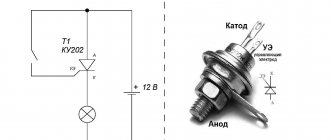
Typical device connection diagram
The principle of simultaneous use of a voltmeter-ammeter on the test section of soil works. There are three quantities: resistance, voltage, current. The parameters are calculated according to Ohm's law. We know the initial voltage, and the device maintains the current. Knowing the voltage drop between the test rods, we can calculate the ground loop resistance with high accuracy.
There is an error, but it is insignificant in comparison with the measured values. The contact resistance of the test electrode with the ground is generally taken as zero, provided that the rod is clean and not covered with corrosion.
Most modern devices immediately provide ready-made parameters for protective grounding, but in older (but no less reliable and accurate) designs, you will need to perform a simple division operation. In accordance with Ohm's law.
Checking grounding with a megohmmeter follows the same principle, only the measurement error will be higher. Still, the earth is not a conductor of electricity in the usual sense.
How is the ground loop checked?
To carry out the measurement, an appropriate device is used, which is included in the state register of acceptable equipment that is used during research, and has also undergone regular verification.
In this case, checking the ground loop involves the use of two rod electrodes and two probes - the first are installed in the ground, and the second - on the loop bus.
Due to this, the characteristics of the current passing through the ground are checked - if the loss of voltage and power is too great, the installation will not be able to reset the excess potential at the right time, which will lead to an increased risk of electric shock to a person. When a project is being developed that involves the use of increased voltage, special attention is paid to this structural element.
Example of a technical report for a premises
Back
Forward
It is better to use a megohmmeter to assess other safety factors
For example, insulation resistance. We are not talking about direct danger. That is, if you grab a wire with your hand in which the dielectric properties of the insulation are normal, you will not receive an electric shock.
But there is an additional danger: insulation breakdown under load. This unpleasant fact leads to malfunctions and, what’s more scary, to electrical circuit fires.
A megohmmeter for measuring insulation resistance is a voltage generator and a precision instrument in one housing.
The classic version (still used successfully today) produces voltage up to 2500 volts. Don't be afraid, the currents during operation are negligible. But you only need to hold on to the insulated handles of the measuring cables.
The high voltage potential easily reveals flaws in the insulation, and the meter needle shows the true resistance. Before starting work, you should turn off all voltage-supplying circuit breakers and get rid of residual potential: ground the wire.
To measure the breakdown between wires in one cable, two wires are used. They are connected to the cores of the disconnected cable, and measurements are taken. If the resistance is below normal, the cable is rejected. No one knows when a potential breakdown site will cause trouble.
To measure earth leakage, one wire is connected to the protective ground (in the area where the cable under test is laid), and the second to the central core. The voltage for testing should be higher. If the wire cannot be connected to ground, the measurement is carried out by applying a second electrode to the outer surface of the insulation.
If there is a screen (cable armor), a three-wire measurement system is used. the third wire is connected to the shield of the cable being tested.
The general scheme is exactly this, but each model of the device has its own instructions. Modern megohmmeters with a digital display are even easier to understand than the old pointer meters.
Using a megohmmeter, you can also test motor windings. But this is a separate topic. Information for those who think that all these devices are narrow-profile: using a shunt system, you can turn a megaohmmeter into a precision ohmmeter or voltmeter.