The correctness and stability of the operation of all vehicle electronics depends on the serviceability of the generator, because it powers all devices after the engine starts. Therefore, it is important to maintain the generator in “combat” condition, which means servicing it correctly. Periodically checking the generator with a multimeter will identify possible malfunctions of the device and increase its service life. More details on how to check a car generator with a multimeter (with and without removing the device) will be discussed in this article.
Multimeter - what is it
A multimeter is a measuring device used to measure resistance, current or voltage. Also, using such a device you can check the wiring for breaks. Each of these measurements involves the use of separate measuring instruments, such as a voltmeter, ammeter or ohmmeter. Therefore, a multimeter is considered a universal tool (mulmeter = voltmeter + ammeter + ohmmeter). In practice, analog and digital multimeters are used.
What is a multimeter
Analog
This multimeter is equipped with a special hand, like on a watch, by the movement of which the measurements are read. The analog multimeter is also equipped with a measuring scale with resistance, current and voltage values. The device is inexpensive, so it is very popular. The disadvantages of an analog multimeter include measurement errors (this mainly applies to products made in China).
Analog multimeter
Digital
Unlike an analog multimeter, a digital multimeter has an LCD or LED screen that displays data. These devices are easier to use and also have high accuracy, which cannot be said about cheaper analogues.
Digital multimeter
Note! Some types of digital multimeters can work in conjunction with a computer, transferring data obtained as a result of measurements to it.
Video - How to use a multimeter
Checking the combined relay-regulator
If the brush assembly is combined with the relay, the generator will need to be removed for inspection. First, you need to check the combined relay-regulator circuit, which is used today on many foreign cars and even domestic cars.
To do this, you will need to remove and disassemble the generator, since the unit we need is attached to the generator shaft along which the brushes run. We look for a “window” for the brushes on the generator, unscrew the fastening bolt, remove the brush assembly and clean it. It's usually covered in graphite dust.
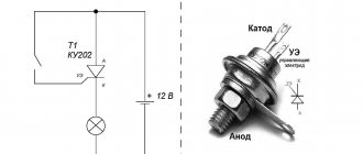
Now we need to build a custom circuit using a power supply with a regulated load. We also need a battery, because the power supply or charger will not work without it. So, we connect the charger to the battery and in parallel to the relay-regulator, and to the latter we also connect a 12 V light bulb.
With this connection, the light bulb will light up - this is normal, since the brush assembly is a conductor, and in a quiet state the voltage here is 12.7 V. Now we need to raise the voltage on the charger to 14.5 V. The lamp should go out when this indicator is reached. After all, 14.5 V is the “cutoff” for voltage growth. And if the lamp goes out, it means that the relay has worked, and in principle it is working.
Otherwise, if the voltage reaches 15-16 V and the light is on, it means that the relay does not cut off. In this case, it must be replaced with a new one.
Now you know how to check the relay regulator with a multimeter, and you can do it yourself.
A relay is a separate device (as opposed to integrated circuits) used to control high power signals with low power signals. The relay separates and protects the low voltage circuit from the high voltage circuit by means of an electromagnetic coil. This article will tell you how to test both the relay (solid state) and the coil.
Possible generator breakdowns
All generator malfunctions can be divided into two types - mechanical and electrical. Mechanical breakdowns can be identified by visual inspection of the device (cracks in the housing, wear of the tension roller or belt, delamination, etc.). To identify electrical faults, special tools are needed.
Common generator problems
Table. Damage to the electrical part of the generator.
| Malfunction, photo | Description |
| Failure of the relay regulator | The relay is responsible for the battery, preventing the generator from recharging it. Failure of the relay-regulator leads to a complete lack of charge. In this case, diagnostics is required. |
| Brush wear | The graphite brushes moving along the generator stator tracks wear out quite often. They need to be changed periodically. |
| Winding burnout | The winding on the rotor or stator may burn out as a result of overloading the device. It can also short out when exposed to moisture. |
| Bearing jamming | During the operation of the car, the alternator bearings wear out, as a result of which the generator begins to jam. This leads to a rupture of the belt and, as a result, to failure of the generator. |
Some faults are difficult to notice, so drivers come to the service center with a generator that is no longer working and a “tired” battery. Therefore, it is important to periodically diagnose the generator using a multimeter.
How to test a generator with a multimeter
Reasons for failure of the relay regulator
The reasons for the failure of the voltage regulator may be:
- short circuit in the circuit, including interturn short circuit of the excitation winding;
- failure of the rectifier bridge (diode breakdown);
- reverse polarity or incorrect connection to the battery terminals;
- penetration of moisture into the housing of the regulator and/or generator (for example, when washing a car or driving in heavy rain);
- mechanical damage to the unit;
- natural wear and tear of the unit, including brushes;
- poor quality of the device being directly tested.
There are a number of simple methods for checking the regulator, regardless of whether the unit is removable or not.
Checking the generator without removing it
Step 1: Set the parking brake and raise the hood.
Lift the hood
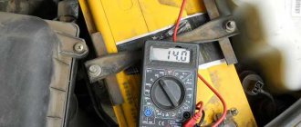
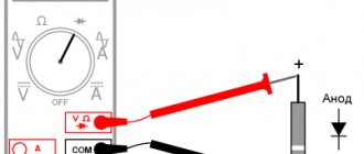
Step 2 . Connect the multimeter to the battery terminals (do not mix up the “+” and “-” terminals). Place the device itself on the battery, as in the photo. When the car is not running, the battery charge should be about 12.5-12.6 V.
Connect the multimeter to the battery
Step 3: Start the engine.
Start the vehicle
Step 4: Monitor your metrics. 1-2 seconds after startup, the voltage should increase to 14.3-14.4 V.
Monitor your multimeter readings
Step 5. Give maximum load to the generator. To do this, you need to turn on all the car's consumers: lights, heater, heated windows and mirrors.
Turn on the light
Turn on the stove
Turn on the heated seats
Step 6. Monitor the battery voltage. If the indicators have changed slightly (14.1-14.2 V), then this indicates normal operation of the generator. If the voltage drops significantly when the devices are turned on (to 13-13.5 V), then diagnostics of the generator is needed.
Monitor the voltage coming from the generator
Check with removal
No preparations or preparatory steps are required for testing. You just need to remove the generator itself and prepare a multimeter. A full check of the device consists of diagnostics of the relay regulator, diode bridge, stator and rotor windings. Let's consider the procedure for checking each of these elements separately.
Checking the generator with a multimeter and removing
Checking the relay regulator
Step 1. Remove the relay regulator and prepare a multimeter.
Remove the relay regulator
Step 2. Prepare a light bulb with two wires (as in the photo).
Connect a light bulb with two wires
Step 3. Connect the wires from the light bulb to the brushes ( See Replacing generator brushes ) of the relay regulator.
Connect the wires to the brushes
Step 4. Now you need to connect an regulated power supply to the “+” and “-” relays.
You need to connect the power supply to the plus and minus
Step 5. Connect the negative of the power supply to the negative of the relay. Secure the wire using a metal crocodile clip.
Connect the minus of the power supply to the relay
Step 6. Connect the second terminal of the power supply in the same way.
Now connect the plus
Step 7. The finished design should look like this.
This is what the design looks like
Step 8. Now connect the multimeter to the terminals of the relay regulator. Everything is the same: “minus” to “minus”.
Connect the negative of the multimeter to the relay regulator
Step 9. Connect “Plus” to “Plus”.
Connect the positive terminal of the multimeter
Step 10: Turn on the power supply to supply voltage to the relay. The multimeter shows 3.8 V after switching on.
Turn on the power supply
Step 11. Gradually increase the voltage, look at the light bulb and the meter readings. The brightness of the light bulb gradually increases.
Slowly increase the voltage on the power supply
Step 12. At around 14 V, the light should go out suddenly. If this happens, then the relay regulator is working properly. Otherwise, replacement of this element is required. At this point, testing the relay-regulator under load can be considered complete.
When the voltage increases to 14 V, the lamp should go out
Checking the diode bridge
Step 1. To work, prepare a multimeter with a ringing function and a diode bridge, which must be removed from the generator in advance.
Prepare the diode bridge and multimeter
Step 2: Check the first diode. It has positive polarity. The resistance of a working diode when tested in one direction should be from 400 to 700 Ohms.
Check the first diode with positive polarity
Step 3. In the other direction the resistance should be infinity. If this is the case, then the diode is fully operational.
Test the diode in the other direction
Step 4. Test the second negative diode in the same way.
Check the second negative diode
On a note! The resistance of the diodes can vary within certain limits and depend on the ambient temperature. When heated, the resistance decreases, and when cooled, it increases.
Step 5. Using this diagram, check all the remaining diodes. A burnt-out diode will have a resistance of infinity.
Repeat the procedure for the remaining diodes
Step 6. Small diodes are tested in the same way as large ones. The resistance of these diodes will be slightly lower than that of larger ones. A slight difference in the resistance of these diodes is considered normal. This completes the check of the generator diode bridge.
Check the small diodes on the bridge in the same way
Stator check
Step 1. Prepare the generator winding for testing. It is advisable to do this in a well-lit place.
Prepare the stator for diagnostics
Step 2. Take a multimeter and set it to test.
Set the ringing mode on the multimeter
Step 3. The winding has three outputs and they should all “ring” with each other.
The winding outputs should be directed upwards for convenience
Step 4. Connect the first terminal of the multimeter to one output, and touch the second terminal to the other two outputs in turn.
Connect the multimeter terminal to the winding output
Step 5. Check the stator for any holes in the metal. To do this, press the multimeter terminal to the edge of the winding, and the second one to the second edge.
Check the stator for metal damage
Step 6. Connect the second probe in turn to the winding outputs. If there are no signals, then the winding is intact.
Connect the terminal to the winding outputs one by one
Rotor check
Step 1. Prepare the generator rotor for further diagnostics.
Prepare the rotor for diagnostics
Step 2. Take a multimeter and set it to dial mode. The black probe should be in its original place, and the red one should be for measuring voltage.
Set the dialing mode on the multimeter
Step 3. Check the device for serviceability by connecting the black and red probes.
Connect the probes of the device to check its functionality
Step 4. Attach one feeler gauge to one rotor ring and the other to the other. In this way you can check for a break.
Attach the probes to the rotor rings
Step 5. Check the rotor for breakdown. To do this, one probe must be pressed against the ring, and the second against the body. If there is no breakdown, then the multimeter shows infinity.
Check the rotor for breakdowns
Step 6. Set the multimeter to resistance measurement mode in the 200 ohm range.
Set the resistance measurement mode on the multimeter
Step 7. Place one feeler gauge on one rotor ring, and the second on the other (as done previously). If the winding is intact, then the resistance should be around 3 ohms.
Reattach the probes to the rotor rings
Mobile stand for testing relay regulators of automobile and tractor equipment
Hello everyone. I haven’t posted anything here for a long time. Which is not surprising, I started doing several interesting things at once at the same time. But soon they will also end up in “Completed Projects”. For now, a small project, so to speak, a “weekend”. The proposed device was assembled in a day and a half without orders.
Well, for starters, what is a relay regulator, for those who are not in the know... This thing monitors the voltage in the on-board network of a car or other equipment and maintains it within specified limits, turning on and off the excitation of the generator. If it is faulty, at best the batteries will undercharge or there will be no charging at all, and in the worst case, the generator can supply the on-board network with the maximum voltage that it is capable of. For example, instead of 28 volts, the volts may turn out to be 30-35 volts. And okay, if it’s an old MAZ, well, the light bulbs will burn out, the battery will boil out .But if this MAZ is Euro-3, then a lot of interesting things are already burning there, especially if 25 ampere fuses are inserted everywhere. I’m not talking about something like Iveco or a Kobelko excavator, and it doesn’t seem like much for a passenger car, except for the car itself, everything is electronic The “toys” that were put there will be covered with joy.
And those relay regulators that are sold, as a rule, give out the most bizarre voltage and it’s clearly not worth installing them without testing. And besides, no matter what base or quarry you come to regular customers, these same relay regulators are brought in for testing by the dozens….
But this is a lyrical digression, so to speak. Further, those who do not deal with auto-tractor equipment, in principle, may not read, it may not be interesting. But you can read for general development….
In general, on a day when there were no orders, I decided to do something useful. For example, a mobile stand for testing relay regulators. I have it, but it works from the network. But I need it on the road. So we will do it with power from 12 volts...
Here's what I got
The device is powered by 12 volts, but can test relay regulators of both 12 and 24 volts, respectively, from cars and trucks and various equipment. In this case, relay regulators Y120 and analogues are checked directly on the instrument panel
And everything else is connected through the terminals on the panel and wires with small crocodiles. The device is powered through a power cable, the same with crocodiles, from any battery. In the transport position, the power cable is retracted inside the case and closed with a lid.
The device provides testing of any regulator relays, both domestic and imported, except those that are controlled from the “brains” of the ECU. But there are not many of them and you almost never come across them on the road. In addition, they are not bad and are checked by diagnostics.
As usual, when assembling, the maximum use was made of components and spare parts from various incomprehensible equipment, which I immeasurably collected from scraps. And this collection is constantly being replenished.
In general, as usual, it turns out that the form determines the content. First, I came across a line panel of a reclaimed switchboard for field telephones in a test box.
The entrails have been removed.
Then it was the turn of a couple of electronic modules from Aliexpress. I constantly buy them for future use - they cost pennies and are needed constantly. I will need a voltmeter like this for 50 volts constant
And here is a voltage converter that produces an output voltage from 12 to 35 volts. Unfortunately, it does not have short circuit protection, but the cheapest and rather “oak” fuse usually burns earlier
And here it has a tuning resistor, which sets the voltage. We carefully unsolder it and solder two wires for external voltage control.
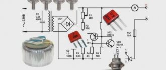
Now you can draw a diagram. Of course, to match the remaining details available
On the elements R1, R6, C1, VD1, VD2, the car relay K1 and the SB1 button, an automatic fuse is assembled against short circuits and large overloads, as well as power overload. I often use this circuit in different variations. We turn on the fuse with the “start” button, then the power lamp La1 is shown. When a short circuit occurs, the relay will turn off and the lamp will go out. I think anyone who decides to repeat it will understand how the fuse circuit works. If something happens, I’ll tell you in more detail later.
Switch SA1 switches between 12 volt and 24 volt modes, and also removes power from the regulator relay test circuit in the middle position.
The external voltage control circuit of the converter is assembled on elements R3, R4, R5. In 12 volt mode, the voltage varies within 12-16 volts, in 24 volt mode within 22-31 volts, which is just enough for testing. The output voltage is controlled by a digital voltmeter.
Switch SA2 switches the “voltage more or less” modes of the Y120 regulator relay and similar ones in the terminals of the device
The load of the regulator relay is the lamps La3 and La2; when they go out, they indicate that the regulator relay has turned off the excitation and it is time to read the readings from the voltmeter. In 12 volt mode, one lamp works, in 24 volt mode, two.
Switch SA3 is used to select where the second output of the generator brushes should be connected for the relay-regulator being tested: to plus or minus. In principle, it could not be installed: only old ZILs and LAWS are connected to minus, but they are still in large quantities come across in our area in the form of aerial platforms and the like, and even from regular large clients, so let it be
And now we take a bunch of swag from the junkyard and complete the panel. All the light bulb sockets, switches, buttons, terminals, etc. are from military equipment. Wirewound resistor R1 is from some kind of board from an ancient frequency generator. The clamp for the Y120 regulator relay is made of M6 brass screws.
The panel itself is cut from a textolite plate from the side of the mentioned remains of the frequency operator. There are several extra holes there - well, never mind. It will still look military-oak. The power supply rubber cable is from some kind of spare parts.
And we put it all together
I’m too lazy to make a false panel - we print the nameplates on a printer, laminate them and put them on good double-sided tape. I often do this - in case something happens, it doesn’t take long to update. And we put a voltmeter in place.
The converter is placed on stands on top of the voltmeter. Don’t forget to coat all the Chinese boards with varnish - it can work outdoors. And we additionally secure the inductor and a couple of large electrolytes on the converter board with hot glue. And we connect everything with a wired installation. I understand that slippers are about to fly at me on the subject: “how is it possible, there are no controllers and boards.” But why the hell is it not needed here. And several small parts are soldered well on the bar with contacts from the mentioned switch. And the final touch is to tighten the wiring harness with the smallest clamps.
We insert everything into the case. Just in case, I glued an insulating gasket from a piece of an old mouse pad to the bottom of the case. Although, in principle, it would not have closed anyway - there is a gap of 7 millimeters to the highest part. All that remains is to solder three wires with crocodiles to connect to relay-regulator terminals. These wires are not included in the photo.
We take half a bucket of accumulated relay regulators and enjoy the result.
And here is a close-up of the clamping device - I think everything is clear from the picture
And here it is in transport position...
And finally, if anyone has not yet understood how to work with the device:
-The 12\24 switch is in the middle position, the voltage regulator knob is on the far left, the +\-switch is in the desired position (I told you about it earlier)
-Connect the power cable.
-Press the “Start” button and the light will come on.
-If it doesn’t light up, the polarity is wrong, change it and press “Start”
-Connect the relay regulator
-Turn on the 12/24 volt switch to the desired position, the excitation lights and the voltmeter scale will light up.
-Slowly turn the voltage regulator - the voltmeter readings increase
-When the lights go out, at this moment we read the readings. This is the voltage that the relay in the car’s electrical system will produce.
-If the protection is knocked out, the excitation lights do not light up or go out, we send this relay-regulator to the land of eternal hunting...
But if the relay normally turns off the excitation, I don’t write what voltage should be considered normal - if someone decided to assemble such a thing, then he already knows...
Additional recommendations
Before starting the test, you need to familiarize yourself with the type of generator set, because the relay regulator can support different values depending on the car model. We are talking about the range from 13.6 to 14.2 V. All these subtleties need to be learned before starting the test, because the final result may depend on them.
Checking the car generator
Otherwise, the process of checking the generator is simple, so even without experience, the driver can do it on his own. Of course, you need to start by checking the generator without removing it. Only by its results can you determine whether the device needs to be dismantled or not. Also, during the test, you can identify other faults related to the generator or other electrical devices of the car.
Generator diagnostics will help prevent serious malfunctions