Design
- The switch consists of three poles (columns) mounted on a common frame and controlled by one spring drive PPrM or spring-hydraulic drive PPrG-2. A single-pole version with PPRM drive control is possible.
- Explosion-proof design.
- Low leakage rate - no more than 0.5% per year.
- Modern technological and design solutions in the field of application and processing of materials.
- The steel parts of the switch and supporting metal structures have corrosion-resistant coatings.
- Basic design of switches without supporting metal structures. Switches can be supplied upon request with high factory support stands, as well as with shortened factory stands to replace low-oil circuit breakers of the VMT series.
- Maintaining the electrical strength of the switch insulation at a voltage of 84 kV in the event of loss of excess gas pressure in the switch.
- Switching off capacitive currents without repeated breakdowns, low overvoltages.
- Low level of audible noise when triggered.
- The presence in the automatic control drive of two heating stages (anti-condensation and main) of the drive cabinet and monitoring of their serviceability.
- Components (devices), including high-quality tires, are purchased from leading, well-established domestic and foreign manufacturers.
- The design of the circuit breaker makes it possible to supply the Customer with products in convenient containers of minimal volumes with minimal transportation costs, as well as to ensure convenient and prompt installation and commissioning. Installation and commissioning is carried out under the guidance of a chief engineer.
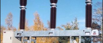
Column switch design
The switches consist of three poles (columns) mounted on a common frame and controlled by one spring drive PPrM. Explosion-proof design.
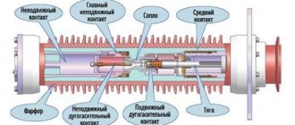
Reduced effort to operate the switch. The energy required to extinguish short-circuit currents is partially used from the arc itself due to the special design of gas flow control units, which significantly reduces the drive load and increases reliability. The use of four stages of seals in conjunction with a hydraulic seal in the rotary mechanism shaft seal assembly ensures a consistently low level of leakage: no more than 0.5% per year.
Modern technological and design solutions in the field of application and processing of materials, the use of reliable components, including high-quality tires from leading foreign companies.
The steel parts of the switch and supporting metal structures have corrosion-resistant coatings.
SF6 circuit breakers VGT-110 can be supplied upon request with shortened factory support posts, as well as with or without high support posts.
Advantages of the SF6 circuit breaker VGT-110
- Maintaining the electrical strength of the column switch insulation at a voltage of 84 kV in the event of loss of excess gas pressure in the switch;
- Switching off capacitive currents without repeated breakdowns, low overvoltages;
- Low level of audible noise when triggered (meets environmental requirements);
- Low dynamic loads on foundation supports;
- The reliability and safety of the PPrM spring drive is confirmed by many years of experience in controlling column switches;
- The presence in the automatic control drive of two heating stages (anti-condensation and main) of the drive cabinet and monitoring of their serviceability;
- Components are purchased from leading, reputable domestic and foreign manufacturers;
- The block-modular design of the SF6 gas circuit breaker VGT-110 makes it possible to supply the customer with products in a convenient container with a minimum volume at minimal transportation costs, as well as to ensure convenient and prompt installation and commissioning, which are carried out under the guidance of a chief engineer.
Advantages:
- Maintaining the electrical strength of the switch insulation at a voltage of 84 kV in the event of loss of excess gas pressure in the switch.
- Switching off capacitive currents without repeated breakdowns, low overvoltages.
- Low level of audible noise when triggered (meets environmental requirements).
- Low dynamic loads on foundation supports.
- The reliability and safety of the PPrM spring drive is confirmed by many years of experience in controlling column switches.
- The presence in the automatic control drive of two heating stages (anti-condensation and main) of the drive cabinet and monitoring of their serviceability.
- Components are purchased from leading, reputable domestic and foreign manufacturers.
- The block-modular design of the circuit breaker makes it possible to supply the customer with products in convenient containers with a minimum volume at minimal transportation costs, as well as to ensure convenient and prompt installation and commissioning, which are carried out under the guidance of a chief engineer.
OSHOBHblE ADVANTAGES.
- reduced effort to operate the switch. The energy required to extinguish short-circuit currents is partially used from the arc itself, which significantly reduces drive operation and increases reliability;
- the use of double seals in connections, as well as a “liquid seal” in the sealing unit of the moving shaft. The natural level of leaks - no more than 0.5% per year - is confirmed by testing each switch at the manufacturing plant according to the methodology used in space technology;
- modern technological and design solutions and the use of reliable components, including high-strength insulators from foreign companies.
- high factory readiness, simple and quick installation and commissioning.
- high corrosion resistance of coatings used for steel structures of the circuit breaker.
- high switching resource specified for each pole (item 3.3), exceeding by 2-3 times the switching resource of the best foreign analogues (per each pole), combined with a high mechanical resource, increased service life The service life of seals and components provides, under normal operating conditions, no less than a 25-year service life before the first repair.
- the ability to disconnect load currents in the event of loss of excess gas pressure in the circuit breaker.
- maintaining the electrical strength of the switch insulation at a voltage equal to 1.15 of the highest phase voltage in the event of loss of excess SF6 gas pressure in the switch.
- disconnection of capacitive currents without repeated breakdowns, low overvoltages.
- absence of ferroresonance in networks during operation of the VGT-220 switch.
- low noise level when activated (meets high environmental requirements).
- low dynamic loads on foundation supports.
- full interchangeability (in terms of connecting and installation dimensions and drives) with low-oil circuit breakers of the BMT series.
Specifications
| Parameter name | Norm |
| Rated voltage, kV | 110 |
| Highest operating voltage, kV | 126 |
| Rated current, A | 2000/3150 |
| Rated breaking current, kA | 40 |
| Normalized percentage of aperiodic component, % not more than | 45 |
| Normalized parameters of the switching current, kA · largest peak · initial effective value of the periodic component | 102 40 |
| Normalized parameters of the through short-circuit current, kA: · the largest peak (electrodynamic resistance current), kA · the root-mean-square value of the current during its flow, kA · the time of the short-circuit current flow, s | 102 40 3 |
| Rated shutdown current of an unloaded overhead line, A | 31,5 |
| Rated shutdown current of the capacitor bank, A | 320 |
| Own shutdown time, at rated voltage on control elements, ms, no more | 38 |
| Total shutdown time, at rated voltage on control elements, ms, no more | 55 |
| Own turn-on time, at rated voltage on control elements, ms, no more | 60 |
| Normalized dead time during automatic reclosure, s | 0,3 |
| Different times of closing and opening contacts of poles s, no more · when switching on · when switching off | 0,0018 0,0015 |
| Specific creepage distance, cm/kV | 2,5 |
| Permissible level of gas leakage per year, % no more | 0,5 |
| Pressure of SF6 gas (SF6) version U1 or gas mixture (SF6 +CF4) version UHL1* reduced to 20°C, MPa, excess: nominal (filling) warning alarm activation control blocking (or automatic shutdown with switching blocking) | Sf6 SF6+CF4 0.4 0.6 0.35 0.52 0.32 0.5 |
| Rated voltage of on and off electromagnets, V, constant | 220/110 |
| Rated voltage supply of the drive electric motor, V, · three-phase alternating · single-phase alternating · constant alternating | 400 or 230 230 220 |
| Current of electromagnets on and off at rated voltage, A, no more | 3/5 |
| Rated supply voltage of heating devices, V, single-phase alternating | 230 |
| Number of pairs of switching contacts for external circuits: · normally open; · normally closed. | 12 12 |
| Switching temperature of the main drive heating devices, °C | 5 ± 2 |
| Dimensions (without prefabricated support structure), mm, length, width, height three-pole / single-pole version | 4180x870x3790 / 1637x871x4396 |
| Switch weight, kg (three-pole / single-pole version) | 1570/925 |
TECHNICAL DATA.
| NNp/p | Parameter name | VGT-110II* 40/2500 U1 | VGT-110II* 40/2500 HL1* | VGTZ-110II* 40/2500 U1 | VGTZ-110II* 40/2500 HL1* | VGT-220II* 40/2500 U1 | VGT-220II* 40/2500 HL1* | VGTZ-220II* 40/2500 U1 | VGTZ-220II* 40/2500 HL1* | ||||
| 1 | 2 | 3 | 4 | 5 | 6 | 7 | 8 | 9 | 10 | ||||
| 1 | Rated voltage, kV | 110 | 220 | ||||||||||
| 2 | Highest operating voltage, kV | 126 | 252 | ||||||||||
| 3 | Rated current, A | 2500 | |||||||||||
| 4 | Rated breaking current, kA | 40 | |||||||||||
| 5 | Nominal relative content of the aperiodic component, %, no more | 40 | |||||||||||
| 6 | Parameters of the through short-circuit current, kA - largest peak - initial effective value of the periodic component - thermal resistance current - flow time of the thermal resistance current, s | 102 40 40 3 | |||||||||||
| 7 | Turn-on current parameters, kA - largest peak - initial effective value of the periodic component | 102 40 | |||||||||||
| 8 | Current of unloaded lines, disconnected without repeated breakdowns, A, no more | 125 | |||||||||||
| 9 | Current of a single capacitor bank with a solidly grounded neutral, disconnected without repeated breakdowns, A | 0-300 | — | ||||||||||
| 10 | Inductive current of the shunt reactor, A | 500 | |||||||||||
| 11 | Own shutdown time, s | 0.035-0.005 | |||||||||||
| 12 | Total shutdown time, s | 0.055-0.005 | |||||||||||
| 13 | Minimum dead time during automatic reclosure, s | 0.3 | |||||||||||
| 14 | Own switching time, s | 0.062 – 0.018 | |||||||||||
| 15 | Diversity of operation of the poles, s, no more - when turning on - when turning off | 0.0020.002 | 0.020.01 | ||||||||||
| 16 | Gas consumption for leaks per year, % of gas mass, no more | 0,5 | |||||||||||
| 17 | Excess gas pressure, reduced to plus 20°C, MPa (kgf/cm2): - filling pressure (nominal) | ||||||||||||
| SF6 gas | 0.4(4) | 0.4(4) | 0.4(4) | 0.4(4) | |||||||||
| gas mixture | 0.6(6) | 0.6(6) | 0.6(6) | 0.6(6) | |||||||||
| - warning pressure when filling | |||||||||||||
| SF6 gas | 0.34(3.4) | 0.34(3.4) | 0.34(3.4) | 0.34(3.4) | |||||||||
| gas mixture | 0.52(5.2) | 0.52(5.2) | 0.52(5.2) | 0.52(5.2) | |||||||||
| — operating blocking pressure (operation prohibition or forced shutdown with activation prohibition) when filling | |||||||||||||
| SF6 gas | 0.32(3.2) | 0.32(3.2) | 0.32(3.2) | 0.32(3.2) | |||||||||
| gas mixture | 0.5(5) | 0.5(5) | 0.5(5) | 0.5(5) | |||||||||
| 18 | Mass of SF6 gas (gas mixture), kg | 6.3 | 7.1 | 6.3 | 7.1 | 20 | 22.5 | 20 | 22.5 | ||||
| 19 | Test one-minute voltage frequency 50Hz, kV | 230 | 460 | ||||||||||
| 20 | Lightning impulse test voltage (1.2/50μs) - relative to ground - between open contacts | 450 550 | 900 1050 | ||||||||||
| 21 | Leakage distance of external insulation, cm, not less | 280 | 570 | ||||||||||
| 22 | type of drive | spring | |||||||||||
| 23 | Number of drives | 1 | 3 | ||||||||||
| 24 | Rated DC voltage of the drive control electromagnets, V. It is allowed to power the control electromagnets with rectified current, for example, from BPT-1002, BPNS-2 units, etc. | 110 or 220 | |||||||||||
| 25 | Number of control electromagnets in the drive - turning on - turning off | 12 | |||||||||||
| 26 | Operating voltage range of control electromagnets, % of the rated value - closing electromagnet - disconnecting electromagnet | 80-110 65-120 | |||||||||||
| 27 | Nominal value of the steady-state value of direct current consumed by the control electromagnets, A - at a voltage of 110V - at a voltage of 220V | 52.5 | |||||||||||
| 28 | Number of contacts switching for external auxiliary circuits | 10 N.O. + 10 N.Z. | |||||||||||
| 29 | Tripping current of switching contacts for external auxiliary circuits at voltage 110/220V, A - AC - DC | 10/102/1 | |||||||||||
| 30 | Power of the electric motor of the closing spring plant, kW | 0.75 | 1.1 | 0.75 | 1.1 | 0.75 | |||||||
| 31 | Rated voltage of three-phase alternating current of the electric motor of the closing spring plant, V - three-phase alternating current - direct or single-phase alternating current | 220 or 380 220 | |||||||||||
| 32 | Winding time of closing springs, s, no more | 15 | |||||||||||
| 33 | Rated power of heating devices of one drive, W - constantly operating anti-condensation heating - heating that automatically turns on at low temperatures | 501 600 | |||||||||||
| 34 | AC power supply voltage for heating devices, V | 220 | |||||||||||
| 35 | Maximum vertical force on 1 foundation support (front and rear) that occurs when the switch is triggered (pulsed, pulse duration no more than 0.02 s) without taking into account the mass of the switch, N - up | 17300 | |||||||||||
| - down | 18400 | ||||||||||||
| 36 | Static load on one foundation support, N | 9500 | |||||||||||
The switches perform the following operations and cycles:
- shutdown (O);
- inclusion (B);
- switching on - switching off (BO), including without a deliberate time delay between operations (B) and (O);
- shutdown - turn on (OB) during any non-contact pause, starting from tbk, corresponding to tbt;
- shutdown - enable - shutdown (OBO) with time intervals between operations in accordance with paragraphs 3 and 4;
- switching cycles:
- O - 0.3 s - VO - 180 s - VO
- O - 0.3 s - BO - 20 s - BO
- O - 180 s - VO- 180 s - VO
The number of shutdown operations allowed for each pole of the circuit breaker without inspection and repair of arc extinguishing devices (switching resistance resource) is:
- for currents in the range of over 60 to 100% of the rated breaking current - 20 operations (thus, for a three-pole switch, the total switching resource in this current range is 60 operations);
- for currents in the range of over 30 to 60% of the rated shutdown current - 50 operations;
- at operating currents equal to the rated current - 5000 “switch on - random pause - turn off” operations.
The permissible number of switching operations for short-circuit currents should be no more than 50% of the permissible number of switching operations; the permissible number of switching operations at load currents is equal to the permissible number of switching operations.
The switches have the following reliability and durability indicators:
- resource for mechanical resistance before the first repair - 10,000 cycles “switch on - arbitrary pause - shutdown” (B - tn - O);
- service life before the first repair is at least 25 years, if before this period the resources for mechanical or switching resistance have not been exhausted;
- service life - at least 40 years.