Why do you need to check phasing?
The purpose of checking the phasing is to monitor the voltage on each of the current-carrying conductors of electrical equipment for coincidence with the voltage on the corresponding conductors of the electrical network. Indeed, in case of non-compliance, undesirable phenomena such as phase imbalance occur. In industrial electrical appliances (for example, refrigerators) there is a significant reduction in power. In everyday life, this phenomenon can lead to failure of household appliances and various electrical installations.
Such work, in accordance with current legislation, must be carried out by specialists of at least two people who have undergone training, are familiar with the requirements of regulatory and technical documentation for the work being carried out, and have an electrical safety group of 3 or higher. At the same time, they must familiarize themselves with the passport data for the equipment connected to the network and have the necessary measuring instruments to carry out such work.
Scope of application
You should not assume that the scope of application of phase indicators is limited only to industrial installations. Yes, until recently, devices of this class were used by electricians working in enterprises whose technological processes are based on equipment with high-performance electrical machines.
Also read: 11 effective ways to connect wires
But now they are building large cottages and townhouses with a complex power supply system. Even in comfortable apartments, the number of electricity consumers has increased to such an extent that connecting to single-phase power becomes impossible. But connecting a three-phase electric meter correctly without observing the phase order will not work. Any error will cause this meter to operate incorrectly, which will result in an unreasonable increase in electricity bills.
In addition, in areas where it is impossible to connect a central water supply, where water supply is required using powerful three-phase electric pumps, improper connection of the equipment will cause long-term failure. Therefore, the use of a phase indicator in this area is considered mandatory.
Checking the phasing of switchgears
Checking the phasing of switchgears (RU) consists of determining the correct order of phases and alternation in accordance with the phases of the equipment being put into operation. Equipment operating from a three-phase network is subject to mandatory phasing before initial commissioning, after major repairs and other work related to violation of the order of phase alternation and their sequence. Simply put, the phase coincidence of the voltage of each of the phases of the electrical installation with the voltage phases of the electrical network is checked. Before putting electrical equipment into operation, check:
- integrity of cores and conductor insulation;
- core phasing;
- phase alternation.
Operating procedure
The work is carried out in the following order by a licensed RTN electrical laboratory:
- checking the absence of voltage on the equipment being put into operation;
- the cable is disconnected from the busbars;
- one of the conductor cores is grounded;
- the insulation resistance of the conductor cores relative to the ground is measured;
- the conductor is marked, the resistance of which relative to the ground will be zero;
- phasing of the remaining cable cores is performed;
- the cable is connected to the switchgear according to the marking;
- a dialing operation is performed;
- phasing is performed under voltage. The check is carried out between the phases of the same name and the others. If there is no voltage between like phases, but there is voltage between opposite phases, then such a cable is put into operation, and therefore the switchgear.
The Perestroika MSK company has all the necessary permits and specialists who will perform the service of checking the phasing of switchgear and electrical equipment in the shortest possible time at the best prices in Moscow and Moscow Region. The customer is issued a document certifying the quality of the work performed.
Checking the phasing of electrical equipment
Three-phase electrical equipment (transformers, generators, cable power lines) is subject to mandatory phasing before it is first connected to the network or after the completion of the next repair, as a result of which a violation of the sequence of phases could occur. Phasing consists of checking the phase coincidence of the voltages of each of the 3 phases of the electrical installation being switched on with the corresponding network voltages. This kind of check is certainly necessary, because during the assembly, installation and repair of electrical equipment, the phases could be rearranged. In electric machines, for example, it is not excluded that the power terminals of the stator windings are incorrectly designated; Cables in connecting couplings can have conductors of opposite phases connected to each other. In all these cases, the only way out is to perform phasing. As a rule, this technological operation consists of 3 main stages listed below. Checking and comparing the phase sequence of the electrical installation and the network.
This operation is performed before directly switching on parallel operation of several networks operating independently, a new generator and a generator that has undergone a major overhaul, during which the connection diagram of the stator windings to the network may have changed. Only when positive results obtained from phasing are obtained, generators or, say, transformers are synchronized and switched on for parallel operation.
Checking the identity or color of the phase conductors that will subsequently need to be connected. This operation aims to check the correct connection of all installation elements to each other. Simply put, the correctness of the supply of current-carrying conductors to the switching device is verified.
Checking the phase coincidence of voltages of the same name, that is, the absence of a phase shift angle between them. In electrical networks, when phasing power lines and power transformers that belong to the same electrical system, it is enough to perform the last 2 operations, since all generators operating synchronously with the network have the same phase order.
Phasing of cable and overhead lines 35 - 110 kV.
Practical work No. 28
Overhead line phasing
Goal of the work
: study of methods for phasing overhead lines.
There are direct and indirect methods for phasing equipment when putting it into operation.
Direct
These are called phasing methods in which it is performed at the inputs of equipment that is directly under operating voltage. Such methods are widely used in installations with voltages up to 110 kV.
Indirect
These are called phasing methods in which it is carried out not at the operating voltage of the installation, but at the secondary voltage of voltage transformers connected to the phased parts of the installation.
Such phasing methods are less visual than direct ones, but safer. They apply to all installation voltage classes.
With direct phasing
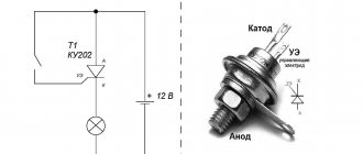
Cable and overhead lines 6 - 10 kV use UVNF type indicators (high voltage phasing indicator).
Rice. 1 Voltage indicator for phasing in 6 – 10 kV installations
The indicator kit includes the voltage indicator itself, a tube with an additional resistor and a conductor connecting them.
Into the housing (tube made of insulating material) of the voltage indicator 1
a signal lamp
7
, a shunt capacitor
10
and three additional polystyrene capacitors
8
for an operating voltage of 1 kV each are installed.
Up to ten heat-resistant resistors
9
into tube 2 , the total resistance of which is 8 - 10 Ohms.
Both tubes are connected in series with wire 4
, which can withstand test voltages of up to 20 kV.
Metal probes are screwed to the upper parts of the tubes 3
, connected to the electrical circuit, to the lower ones - insulating rods
5
with a gripping handle
6
.
For phasing, phasing voltages are supplied to the disconnected device (switch, disconnector) from each of its sides. The pointer probes are brought to the terminals belonging to one pole of the disconnected device, and the warning lamp is observed to glow. In this case, two cases are possible:
· counter switching is switching on to a non-phasing voltage, the indicator lamp in this case should light up brightly, signaling a phase mismatch;
· consistent switching is switching on the voltage of the same phase. In this case, the indicator lamp should not light up. The absence of a lamp glow indicates the same phased voltages applied to the pole terminals and the possibility of connecting these phases to each other by turning on the switching device.
To check the serviceability of the indicator itself, the probe of the tube containing the resistor is touched to ground, and the probe of the other tube is brought to one of the terminals of the device under voltage. In this case, the neon lamp should light up (Fig. 2 a).
Then the probes of both tubes touch one conductive part. In this case, the indicator lamp should not light up (Fig. 2 b).
The voltage is checked at all six terminals of the switching device. This check is carried out in order to eliminate errors in the phasing of a line that has a break.
The absolute values of the voltage between the phase and the ground do not play a role, since during phasing the indicator will be connected either to the line voltage (if the phases are mismatched) or to a small voltage difference between the same phases (if the phases are the same). Therefore, the presence of voltage in each phase is judged by the glow of the indicator lamp.
The phasing process consists of touching the probe of one indicator tube to any extreme terminal of the device, for example, phase C, and the probe of the other tube to alternately touch three terminals from the side of the line being phased.
Rice. 2 Sequence of operations when phasing 10 kV lines using the UVN indicator.
a - checking the serviceability of the pointer when turned on in the opposite direction;
b - the same with a consonant;
c - checking the presence of voltage;
g - phasing.
In two cases of touch (C - A1 and C - B1), the lamp lights up brightly, but in the third (C - C1) it will not light, which will indicate the same phases. After identifying the first pair of pins of the same name, the probes alternately touch other pairs, for example A - A1 and A - B1. The absence of light from the indicator lamp in one touch will indicate that the pair of pins is the same. The phase coincidence of the third pair of terminals B - B1 is checked only for control - the phases must match
Phasing of cable and overhead lines 35 - 110 kV.
For phasing, a voltage indicator of the UVNF-35-110 type is used.
Phasing is carried out on disconnected disconnectors (or separators), the terminals of which are energized: on one side from the switchgear buses, on the other, from the line being phased. First, the presence of voltage is checked on all phases of the disconnectors by touching the indicator probes to the phase and to the grounded structure. If there is voltage, the indicator lamp should light up.
Then, at the extreme phases of the disconnectors, the phase coincidence of voltages is checked (Fig. 3). In the middle phase, no check is carried out.
If the indicator lamp does not light up during phasing at the extreme phases, then the phasing is considered completed - the phases coincide.
When the indicator lamp lights up on both extreme phases or only on one, the phasing is stopped - the phases do not coincide.
Rice. 3 Connecting the indicator to the terminals of the disconnectors when phasing the 35-110 kV line.
Phases of the same name are connected for parallel operation. If pairs of the same name on disconnectors or switches are not opposite each other, the installation is turned off and the buses are reconnected in the order necessary for the phases to match.
Safety conditions during phasing with voltage indicators.
Before you begin phasing, you must ensure that both the general safety requirements for preparing the workplace and the special requirements for working with measuring rods on live equipment are met.
Electrical devices at the terminals of which phasing will be performed must be securely locked before voltage is applied to them and measures must be taken to prevent them from being turned on.
Before starting work under voltage, voltage indicators must be subjected to a thorough external inspection. At the same time, attention is paid to ensuring that the varnish coating of the tubes, the insulation of the connecting wire and the voltage indicator lamp do not have visible damage or scratches. The shelf life of the indicator is checked using a periodic test stamp. It is not allowed to use signs whose expiration date has expired.
When working with a voltage indicator, it is mandatory to use dielectric gloves. During phasing, it is not recommended to bring the connecting wire closer to grounded parts. The working and insulating parts of the indicators should be located so that there is no danger of overlap on their surface between phases or to the ground.
Phasing with a voltage indicator cannot be done during rain, snowfall, or fog, since its insulating parts may become moist, which will lead to their overlap.
Indirect method
Lines of all voltage classes are usually phased, most often with a double bus system.
In a switchgear, where both bus systems are in operation, one bus system is released to perform phasing, placing it in reserve.
When the bus coupling switch (BSB) is turned on, use a voltmeter to check the phase coincidence of the secondary voltages of the voltage transformers of the working and backup bus systems. Then the SSV is turned off and the operating current is removed from its drive.
Fig.4 Diagram of phasing of an overhead line using the indirect method on the secondary terminals of voltage transformers.
The backup bus system includes a line for which phasing should be done. From the opposite end of the line, voltage is applied to it and phasing is carried out at the terminals of the secondary circuits of the VT of the working and backup bus systems.
The order of practical work:
1. Study theoretical information on the topic “Phasing of overhead lines”
2. Draw up a report on the work, answer control questions.
Security questions on the topic:
1. What phasing methods exist, what is their difference?
2. What device is used for phasing 6 – 10 kV lines?
3. How to check the serviceability of the UVNF?
4. What is the sequence of operations when phasing 6 - 10 kV lines?
5. How are 35 – 110 kV lines phased?
6. What is the essence of the indirect phasing method and where is it used?
7. What safety measures are taken during phasing?
Recommended reading:
1. Makarov E.F. Maintenance and repair of electrical equipment of power plants and networks.
M. IRPO: Publishing house 2003.
2. Mandrykin S.A., Filatov A.A. Operation and repair of electrical equipment of stations and networks.
Energoatomizdat 1983.
3. Sibikin M.Yu. Maintenance and repair of electrical equipment and networks of industrial enterprises. – ProfObrIzdat, 2001.
Recommended pages:
Use the site search:
Phasing devices
Today there are many techniques that depend on the intended purpose of the electrical equipment, the winding connection diagrams and the devices and devices used.
The main instruments and devices include:
- AC voltmeters used for phasing electrical installations up to 1 kV and connected directly to the terminals of electrical equipment.
- Phase indicators, the principle of operation of which is similar to the principle of operation of an induction motor (induction motor), when when the instrument coil is connected to a 3-phase current network, a rotating magnetic field is formed, which causes the working disk to rotate. In this case, by the direction of rotation of the disk, one can judge the correct order of the phases of the currents passing through the coils.
- Universal devices (portable volt-ampere phase indicators, universal phase indicators).
- Megohmmeters, which are portable devices necessary for measuring insulation resistance in wide ranges, which have proven themselves very well in the production of phasing.
- Voltage indicators for phasing. These devices are well suited for phasing electrical installations above 1 kV. When performing an operation on a disconnected device (disconnector, circuit breaker), phased voltages are applied to each side. At the same time, the probes of the device are brought to the current-carrying parts of the phased device, and then the glow of the signal lamp on the device is monitored. It is worth considering that the burning of the lamp indicates a phase mismatch, and the absence of the light of the lamp indicates consistent switching on and the possibility of switching on the switching device.
What testing devices are there?
There are two ways to perform a phase check:
- straight. A method in which testing is carried out at the inputs of electrical appliances that are under operating voltage. It is usually used for devices up to 110 kV;
- indirect. A method in which the process is carried out using secondary electrical voltage. This test is usually performed in the presence of voltages of 110 kV and above.
Transformer phasing diagram with jumper installation.
There are not many devices used in testing. Popular among them:
- voltmeters. Typically used in devices with voltages up to 1 kV. They connect directly to equipment terminals or parts of devices that conduct current. As for accuracy, it is not required from such devices;
- phase indicator. The sequence of phases and their order are determined by induction phase indicators. They consist of several coils, inside of which there are ferromagnetic cores and an aluminum disk. The principle of operation of the device is similar to the operation of an asynchronous type electric motor. When it is connected to a three-phase network, all coils begin to rotate the electromagnetic field around them. Because of this, the disk begins to rotate, which shows the phase sequence of the network.
You might be interested in: Application of KGN cable
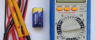
Checking the phasing of three-phase voltage with a multimeter
The process of determining the correspondence (alternation) of the phases of cable lines from power sources to consumers, with a three-phase, parallel connection, is called phasing
or phasing. The main objective of this operation is to determine the current voltage on each of the current-carrying conductors of electrical equipment for coincidence with the voltage on the corresponding conductors of the electrical network
Preliminary and direct phasing
Pre-phasing
carried out directly during the installation process, before turning on the electrical equipment for the first time. And also in case of repair of equipment or power cable, when there is a possibility of a change in the order of the phases, and their inconsistency with each other and the busbars of the switchgear. Pre-phasing work is carried out exclusively on electrical equipment that is not under voltage.
And when putting electrical equipment into operation, indirect or direct phasing of the equipment is mandatory. Since only carrying out this operation can guarantee the phase compliance of all elements of the electrical circuit.
The choice of method, direct or indirect phasing, mainly depends on the type of equipment and the voltage class of the electrical network. The fundamental difference between the methods is that direct
The method is performed at operating voltage and is more visual.
Indirect methods
When commissioning new switchgears (RU)
This method comes down to checking the compliance of the markings (colors) of the terminals of the secondary windings of voltage transformers with the instructions of the PUE. The most objective way to check this operation is to supply electric current phase by phase and check that the colors of the phases in the switchgear correspond to the phases of the power system. At the same time, the marking of secondary circuits is checked by the appearance of voltage at the terminals of one or another phase of the voltage transformer.
The secondary windings of other voltage transformers are subsequently phased with the transformer for which the marking has already been verified. The choice of method depends on the secondary winding circuit: whether its zero point or one of the phases is grounded.
In the first case, a voltmeter with a scale for double phase voltage is used for phasing, in the second - for double line voltage. For example, it is necessary to check the phase coincidence of two voltage transformers connected from the high voltage (HV) side to different bus systems (or sections), then for this the buses are connected to each other by turning on the bus connecting (or section) switch and then phasing is performed.
With double bus system
In this case, phasing is carried out at the secondary voltage of the transformers. To do this, with the bus coupling switch turned on, using a voltmeter, the phase coincidence of the secondary voltages of the transformers of the working and backup bus systems is established. Then one of the systems is transferred to reserve, the switch connecting the buses is turned off and the operating current is removed from its drive. A circuit is connected to the reserve line, the phasing of which must be done and current is supplied to it.
Then phasing is carried out at the terminals of the secondary circuits of the voltage transformers of the working and backup bus systems. Using a voltmeter in the sequence (Fig. 1): a1-a2; a1-b2; a1-c2; b1-a2; b1-b2; b1-c2, take measurements. When the voltmeter readings are zero, the bus connecting switch is turned on, and the phased circuit is switched on for parallel operation.
Phasing diagram for double bus system (Fig. 1)
With positive readings
When using the device, the phased circuit is disconnected and the conductive parts are reconnected. The phasing process is carried out again, ensuring that the phases of the backup and phased circuits match.
Direct method of phasing the 6-10 kV circuit
UVN-80, UVNF and others are used as a voltage indicator. It is mandatory to check the serviceability of the voltage indicator. An external inspection is carried out: for the integrity of the varnish coating, the presence of a stamp indicating periodic testing, and the integrity of the insulation of the connecting cable.
Order periodic high-voltage tests of indicators and other personal protective equipment in the METTATRON electrical laboratory. Submit your application
After an external inspection, they begin to check the serviceability of the pointer.
UVN 80 2M with TF - high voltage indicator with phasing tube
To do this, touch the ground with the probe of the tube containing the resistor, and bring the probe of the other tube to one of the phases of the circuit, which is obviously energized, for a few seconds; the indicator light should light up (Fig. 2a)
.
Then, for several seconds, the probes of both tubes touch one current-carrying part (Fig. 2b)
.
If the light does not light up, then the indicator is working and you can check the presence of voltage in all phases. To do this, the probe of the tube with the resistor is connected to ground, and the probe of the other tube alternately touches all six clamps of the disconnector (Fig. 2c)
. In each case, the warning lamp must be lit.
RETOMETER-M2: features that are important to know about
Using the three-phase device RETOMETER-M2, you can easily determine the phase rotation by measuring the values of phase voltages or their symmetrical components.
For this purpose, the device has appropriate measurement modes. To perform the test, it is enough to connect the device using three wires to the corresponding terminals of the phases being tested (Fig. 1). It is worth noting that this is the only mode when only three wires are enough to measure a three-phase signal; the rest use four or six.
To make sure the connection is correct, you need to check the presence of voltage at each input in three-phase mode (Fig. 2). If the results are incorrect, it is recommended to check the connection diagram or additionally connect the neutral wire.
Next, in the sequence measurement mode, determine the order of phase alternation. With direct alternation, the highest voltage value is in direct sequence, for example, in Figure 3 Up=57.73V. If the alternation is reversed, then the maximum value is reached by voltage Uо. Voltage Un does not participate in determining the alternation. The presence of three voltages Up, Uo and Un indicates an incorrect connection.
| Rice. 1. Checking phase rotation | Rice. 2. Checking the correct connection | Rice. 3. Calculation of the values of symmetrical components |
How to use RETOMETER-M2 to check the phasing of buses of two 0.4 kV sections?
In the device, all voltage measuring channels are galvanically isolated from each other, so this test is performed quickly and safely.
Input U1 is connected to phase “A” or to the linear voltage “AB” of the first bus section, and input U3 is connected to phase “A” or to the linear voltage “AB” of the second bus section (Fig. 4). If the system is phased correctly, then the angle between the voltages will be 0 (Fig. 5), if the ends are inverted - 180 degrees. In the case when the phases in the tires are reversed, the angle is 120 degrees (C or L).
After checking phase “A”, it is necessary to check the other phases in the same way.
| Rice. 4. Checking the phasing of the buses of two sections | Rice. 5. Measuring voltage in two channels and calculating the phase between them |
How to test the secondary circuit of a current transformer?
Measuring the load resistance in the secondary circuit of a current transformer must be performed by applying primary current to it from an external source, or when the transformer is operating in normal mode.
The input of the volt-amperephase meter U1 must be connected to the terminals of the secondary winding of the transformer, and the current clamps I1 must be used to cover any outgoing wire (Fig. 6). Next, set the single-phase mode in the menu and select advanced data display.
Based on the measured current and voltage values, the total, active and reactance resistances are calculated (Fig. 7).
| Rice. 6. Checking the secondary circuit of the current transformer | Rice. 7. Measurement of parameters of one phase |
How to determine the asymmetry of a three-phase voltage system in a 0.4 kV circuit?
RETOMETER-M2 has a wide voltage measurement range, up to 750 V per phase, so the device can be directly used for measurements in 0.4 kV networks.
Indicators of asymmetry of a three-phase voltage system are the asymmetry coefficients for the negative (Ko) and zero (Kn) sequences, which are calculated as the ratio of the effective value of the negative and zero sequence voltage, respectively, to the effective value of the positive sequence voltage.
RETOMETER-M2 automatically calculates the values of these coefficients in the mode of measuring symmetrical components (Fig. 9).
When measuring voltage unbalance coefficients, only a four-wire connection diagram is used (Fig. 8).
| Rice. 8. Determination of voltage asymmetry in a 0.4 kV circuit | Rice. 9. Measurement of coefficients Ko=14% and Kn=5% |
Is it possible to use RETOMETER-M2 to measure the total power consumption in an apartment building?
Yes, it is possible, but provided that step-down current transformers are used in the electrical panel (Fig. 10). To measure power consumption, you must select the three-phase operating mode of RETOMETER-M2 and switch it to the three-phase power measurement mode, where the active, reactive, apparent power of each phase and power factor are calculated. The total active power ΣP is defined as the total power of the three phases (Fig. 11). The resulting value must be multiplied by the CT transformation ratio.
| Rice. 10.Measurement of total power consumption | Rice. 11. Removing a complete vector diagram of a three-phase circuit |
Why is the ability to carry out measurements at various harmonics added to RETOMETER-M2?
Due to the widespread use of devices that use thyristors in their circuits, generating harmonics into the network, a large number of disturbances and distortions have appeared in electrical networks, leading to failures of production equipment and to incorrect accounting of consumed or produced energy. The main sources of harmonics are frequency drives and motor soft starters, arc welding, transformers, etc.
Harmonics generated by the sources do not remain in this system, but appear in neighboring connected power networks and can lead to catastrophic consequences, causing overheating and failure of power transformers, increased current or overload of correction capacitors, noise and malfunctions of control systems, overload of rotating devices, errors in operation of circuit breakers and errors in communication equipment, high current in the neutral, voltage changes in phases, etc.
In order to prevent an increase in the level of nonlinear distortions in the network, absorption (heat generation) of harmonics, as well as for the rational use of electricity, it is necessary to use special measuring instruments with harmonic filters.
Any periodic current or voltage curve can be decomposed into a basic sinusoid (50 Hz) and the sum of a certain number of frequencies that are multiples of 50 Hz. Odd harmonics are of greatest importance, so the influence levels of 3, 5, 7, 8, 9 in total can exceed 10% of the 1st harmonic. Other harmonics have much less influence.
What is phase rotation?
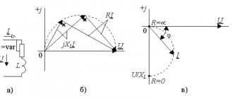
Phase alternation should be understood as the sequence in which the voltage increases in each of them. In all three-phase circuits, the voltage is a sinusoidal curve. In each line the voltage differs by 120º from the others.
As you can see, in Figure 1, where a) shows the voltage curves in all phase wires, shifted by 120º. The adjacent figure b) shows a vector diagram of these voltages. Both figures show the difference between phase and line voltage.
If we take as a basis that U A comes out of the zero point in figure a), then this phase is the first, in diagram b) the arrows clearly show that the order of voltage increase goes from U A to U B, and then to U C. This means that the phases alternate in the order A, B, C. This order of alternation is considered direct.
Direct and reverse phase rotation
In a three-phase network, the order of phase rotation may differ depending on the connection methods to power transformers at substations, the sequence of switching on the generator windings, due to mismatch of cable terminals and other reasons.
Please note that the color marking determines the sequence according to their order in the alphabet according to the first letters of the color:
- Yellow – first;
- Green – second;
- Red is the third.
Figure 2 shows the classic version of the forward sequence A - B - C (where A is yellow and is the first, B is green and is the second, and C is red and is the third) and the classic version of the reverse sequence C - B - A. But , in addition to them, in practice there may be other options, direct: B – C – A, C – A – B, and reverse alternation: A – C – B, B – A – C. Accordingly, in each of the above examples, phase alternation will start from the first one.
Phase meters purpose, device and scope, review of models
A phase meter is a device used to obtain accurate information about the magnitude of the phase shift between two electrical oscillations that change from time to time. The device is typically used for measurements in a 3-phase network.
Phase meters are often used in electrical installations to calculate reactive power factor (cosine phi). The device is actively used in the operation of electrical substations and networks, in the development of electronic and electrical products.
Briefly about the phase meter
To carry out measurements, the phase meter is connected to voltage circuits, which act as a reference point, and a current circuit, which shows the position of the measured vector. When operating on a 3-phase network, it may be necessary to connect to all phases.
The peculiarity of modern devices lies in the simplified principle of use, so understanding the features and subtleties of using a phase meter will not be difficult even for an inexperienced specialist.
The measurement is made for two phases, after which the last phase is calculated based on vector addition. In addition, the phase meter is often used to measure the cosine phi, as mentioned at the beginning of the article.
Kinds
All phase meters according to the operating principle are divided into three types:
- Electrodynamic;
- Digital;
- Electromechanical.
The first two types are in greatest demand, but it is recommended to use digital devices. They are characterized by greater accuracy and low noise levels.
According to the number of phases, phase meters are:
- Single-phase - for carrying out measurements in a 1-phase circuit.
- Three-phase - for 3-phase circuits.
Electrodynamic
Until recently, electrodynamic (electromagnetic) phase meters were in greatest demand. Structurally, this device consists of a simple ratiometric mechanism that allows accurate measurement of phase displacement.
The device has two frames that are rigidly connected to each other. The angle between the mentioned elements is 60 degrees. The frames are mounted on axes fixed to support units. Thanks to this feature, the device has no mechanical resistance.
The device has a special element that rotates through an angle that characterizes the magnitude of the current phase shift. Using a linear scale, the technician can record the measurement and determine the current offset setting.
The electrodynamic phase meter is based on a fixed current coil, as well as two more similar, but movable elements. The displacing coils have their own currents flowing, which contributes to the appearance of a magnetic flux in all coils - moving and stationary.
When the coil flows interact, a pair of rotating moments appears, the magnitude of which depends on the distance between the moving elements of the device. The mentioned moments have different directions, which are opposite in magnitude.
POPULAR WITH READERS: Recommended tools for the home
The torque indicators depend on the currents flowing in the moving coils, as well as on the current level in the fixed coil. In addition, the mentioned indicators depend on the design features of the coil and the angular phase shift.
As a result, the moving element of the phase meter rotates under the influence of the mentioned moments until a situation where equilibrium does not arise, that is, the moments become equal.
The phase meter itself often has a gradation that allows you to accurately measure the power factor.
The advantages of the device are reliability, high accuracy of readings, and affordable price.
The disadvantage is the dependence of the measured parameters on the frequency indicator. Another disadvantage is the increased power consumption from the source being studied.
Digital
As noted, this is the preferred type of device due to its more convenient use and high accuracy. Such devices are manufactured using various technologies.
For example, a compensation phase meter makes the most accurate measurements, despite the need for manual use. The device operates on a different principle. During the measurement process, a pair of U appears, having a sinusoidal type, and the main purpose of the device is precisely to calculate the shift between phases.
First, U is fed to a phase shifter, which is controlled from a special device. The measurement process occurs smoothly until the phases coincide. During the setup process, the phase shift value is calculated using a phase-sensitive device.
The output signal is transmitted from the detector to the control device. The given algorithm is implemented by encoding pulses. Once balancing occurs, the phase shifter code reflects the information of interest.
At the present stage, digital phase meters use a technique that is based on discrete counting. The essence of the method is to go through two stages.
First, a process will be carried out to convert the phase offset into a signal parameter with a certain duration. Next, the length of this pulse is changed using discrete counting.
The device includes:
- Converter that converts phase displacement into pulse;
- Time selector;
- An element that generates discrete pulses;
- Control device and counter.
The advantages of digital type phase meters are lower error due to calculations performed over several periods, greater accuracy and ease of use. Disadvantages - higher price.
User manual
To understand the use of the phase meter, the main attention is paid to the operating instructions (included with the device). There are a few steps you need to take before you begin.
First, you should make sure that the operating conditions correspond to those recommended by the manufacturer, and the frequency range is in accordance with the metrological characteristics. After this, the circuit itself is assembled.
The phase meter is operated according to the following algorithm:
- First you need to read the instructions that come with the product. The document reveals the nuances and rules for using the device.
- Using the corrector, the arrow is set at the 0 mark.
- Make sure the buttons are not actuated.
- Connect the input probes to the required connectors.
- Press the key that supplies power to the device. Pay attention to the lighting of a special indicator.
- Wait a while for the device to warm up well. This is necessary to achieve maximum measurement accuracy. On average, the exposure time should be about 10-15 minutes.
- Find the input voltage.
- Press the button depending on the choice of external voltage and set the required frequency range.
- Click ">0
Source: https://ElektrikExpert.ru/fazometr.html
Why do you need to consider phase order?
The sequence of alternations plays a significant role in such situations:
- When connected in parallel, a number of devices (transformers, generators and other electrical machines) can be connected in parallel operation to increase the reliability of the system or to provide a greater power reserve. But, in case of incorrect connection, a short circuit will occur due to the connection of opposite phases.
- When connecting a three-phase meter - since its operation is based on the coincidence of phases with the corresponding terminals of the device, then if the connection is not correct, a failure and spontaneous movement may occur in the absence of any load. Because of this, such a connection of the electric meter will lead to the need for the consumer to pay for kilowatts that he did not consume.
- When the engine is turned on, the sequence of phases in the network determines the direction of rotation of the engine for the electric machine. In the absence of correct phasing, the direction of movement of the elements mechanically connected to the rotor will also change. This could result in a disruption of the technological process or a threat to the lives of personnel.
How to check?
Checking can be done in several ways. The feasibility of choosing one or another option depends on the parameters of the electrical network and the problems that need to be solved. So the alternation can be recognized using a phase indicator, megohmmeter, multimeter or by the color of the cable insulation. Consider each option in more detail.
Using a phase indicator
According to the principle of operation, the phase indicator can be compared with a conventional asynchronous motor. Let us consider as an example the most common model of a phase indicator - FU-2.
As you can see in Figure 3, the phase sequence indicator has three windings that are connected to the same phases in the network or device. Between the windings there is a rotating rotor P, which drives the phase indicator disk D.
In practice, after connecting the corresponding wires to the phase indicator terminals, the worker presses the K button, which closes the circuit of the windings. Depending on the order of phase alternation, disk D will begin to rotate clockwise or counterclockwise.
On the device itself there is an arrow indicating direct alternation. If, when the button is pressed, the disk rotates in the same direction as shown by the arrow, then this three-phase load is direct interleaved. If the disk starts to spin in the opposite direction from the arrow, then the phase sequence is reversed. It should be noted that this device is not able to determine which phase is on which wire, it can only determine the order of their alternation.
Using a megohmmeter
As one of the methods for testing conductors, a device for measuring resistance - a megohmmeter - is widely used.
Look at Figure 4; to implement such a scheme, you will need to disconnect the cable from the network and from the consumer. At the same time, at one end of the cable, the phases are alternately connected to ground Z, just like the metal sheath of armored cables. On the other side, a megohmmeter M is connected, one of the terminals of which is grounded, and the second is alternately connected to each of the phases. On the one where the megohmmeter shows zero resistance, there will be one wire.
Appropriate markings are installed at the ends of the wire of the same name. The disadvantage of this method of dialing is the large amount of labor costs. Since each core is grounded one by one, after which a test is performed. In this case, responsible employees must be installed at both ends of the cable. Communication must be ensured between them to coordinate actions and prevent voltage from being applied to workers.
By color of core insulation
If any device has a connection with multi-colored wires, then the phasing of the equipment can be done by color. To determine the location of the same voltages of certain phases, it is necessary to get to each cable core. If each wire has insulation of different colors, then by comparing them with the place of connection to the transformer or switchgear, you can determine where each phase is located.
The disadvantage of this method is false color marking, since the cable manufacturer does not always provide the same color for each core along the entire length of the wire. Therefore, it is still recommended to ring and mark it first.
Using a multimeter
For this method, a regular multimeter is used. It is most relevant in situations where it is necessary to include two adjacent devices in parallel operation and their buses are located nearby.
It is necessary to compare the phase voltages in adjacent lines; Figure 5 shows an example for phases A and A1. The switching equipment must be open. Before using a multimeter, the voltage class is set on it for the line on which the measurement will be made. The probes are brought to the phase terminals, while their insulation must provide protection from voltage, and dielectric gloves are put on the hands.
If, when connecting the probes to terminals A - A1, the arrow remains at the zero mark, this means that the phases are the same. If the arrow deviates by the amount of line voltage, you are measuring opposite phases.
Classification of phase indicators
Regardless of the scope of application, the following types of phase indicators are most widely used to check the correct connection of household or industrial electrical devices:
- Induction - represented mainly by outdated models such as I517, FU-2 and more modern modifications. In essence, they are a simplified model of an asynchronous motor, the rotor of which is made of an ordinary disk made of light metals. When directly connected to the power supply, this indicator disk begins to rotate clockwise, otherwise the direction of rotation is reversed. Devices of this type are characterized by a long working life and ease of use. Some modifications are used to work with three-phase networks with a frequency of up to 1 thousand Hertz.
Induction phase indicator - Devices that provide indication of correct switching using conventional incandescent lamps or LEDs are considered more modern. They are smaller in size and therefore easier to use, especially at home. We note the imperfections of some models, which require connection to only two phases and a neutral wire; this somewhat complicates the work on determining the phase order.
Phase indicator with indicator type - Microcontroller-type devices also deserve attention. They are quite suitable for performing work at home and in production; the correct phasing is shown using the same light indicators.
Microcontroller type phase indicator
I517M:
FU-2:
The principle of operation of all devices, except induction, is based on the effect of phase imbalance, in which different active and reactive resistance appears in different circuits. As a result, this leads to a change in the intensity of the glow of individual indicators or a complete refusal to turn on.
Protection against alternation violation
To protect electrical equipment from incorrect rotation, a phase control relay is used in practice. This relay is configured to operate the engine or other device when it is connected directly. If due to some malfunction or incorrect connection the alternation is disrupted, the three-phase relay will immediately turn off the device. His work is based on the analysis of three-phase currents and voltages and subsequent monitoring of these parameters.
The connection can be made through current transformers or directly, depending on the model and voltage class of the network. Such protection has found wide application when connecting induction-type meters, electrical machines and other high-precision equipment.
Source