Tuning VAZ 2109
Many improvements to the electrical equipment of a car include the use of power relays.
This article discusses the operating principle and several examples of relays used in cars. This article will be useful to all fans of tuning modifications regarding the electrical equipment of the car. Here are the main characteristics of domestic relays:
- Rated voltage: 12V
- Control current: no more than 0.2A
- Operation voltage: no less than 8.0V
- Release voltage: 1.5 - 5.0V
- Maximum switching current: 30A
- Control winding resistance: 80±10 Ohm
Versions of domestic relays:
- 90.3747-10 - plastic housing without mounting ear
- 90.3747 - plastic case with fastening eye
- 113.3747 - metal case with fastening eye
- 113.3747-10 - metal case without mounting ear
- 111.3747 - metal case with fastening eye
- 111.3747-10 - metal case without mounting ear.
The relay must be used in cases where switching of large load currents (20-40A) is required, and this is more than the control output produces (the winding of the relay control circuit usually consumes no more than 0.2A)
Relays with 4 and 5 contacts are available.
Power relays have winding contacts that control the operation of the power contacts (contacts 85 and 86), and the power contacts themselves (30, 87 and 87a).
The operating principle of a power relay is as follows. Voltage is applied to the relay's control contacts (winding), the winding attracts the relay's power contacts to each other, the relay operates and closes (or opens) the electrical circuit with its power contacts. If there is no voltage at the contacts of the control winding of the relay, contact number 30 is permanently closed to contact number 87a. If voltage is applied to the control winding of the relay, then contact number 30 is disconnected from contact number 87a and connected to contact number 87. One of the contacts, 87a or 87, may be missing. In this case, the relay works either only to close or to open the power circuit.
Some imported relays between the 85th and 86th contacts have quenching diodes or resistors, and sometimes both. These elements protect control circuits from overloads during operation of the relay contacts.
If the diode symbol is marked on the relay body, this means that when connecting such a relay, the polarity of the control contacts must be observed.
It is necessary to pay attention to the markings and arrangement of contacts on the relay, since some manufacturers produce relays with non-standard arrangement of contacts.
It should be noted that during prolonged operation of the relay in maximum load modes, the spark that jumps when switching contacts creates carbon deposits between these contacts, which is why the controlled device may not work or work incorrectly. In the place of poor contact, when current flows, excess heat is generated, the current in the power circuits increases, which entails heating of the place of bad contact in the connected circuit, and subsequently the melting of the plastic parts of the places where these contacts are attached occurs. The attachment points of the relay contacts melt, which leads to their displacement relative to their standard position, and due to the appearance of gaps between the contacts, sparking begins, and as a result of these processes, the contact area heats up even more.
Imported relays are considered more reliable; domestic relays are less sealed and wear-resistant.
When choosing a relay, you need to pay attention to the coating of the relay contacts and the connector where the relay is inserted. The most preferred are relays with tinned contacts.
Types of multimeters and the principle of their design
The most common types of multimeters are analog and digital. Let's look at how they are designed and work below.
Analog
These are old-style testers that look like boxes with a glazed arc-shaped scale and a spring-loaded pointer. Often there is a mirror arc on the scale so that when you look at the arrow you can align the arrow with its reflection. This way, when measuring, you are looking exactly perpendicular to the scale, rather than at an angle, and it will be more difficult for you to make a mistake. The measuring panel has many parallel arc scales for different types of measurements:
Analog multimeter.
One of the main advantages of an analog multimeter is its low price and measurement accuracy that is quite sufficient for everyday purposes. Moreover, most analog multimeters have a built-in special resistor to adjust the position of the arrow exactly to “0”. For adjustment, a resistor head is used, similar to a screw slot, located below the measuring scale approximately at the point where the arrow is attached.
Digital
These multimeters are more modern and look like oblong black boxes with a large liquid crystal display for digital readings. These devices got their name because the analog signals entering the device are converted into digital form in an analog-to-digital converter (ADC). Such devices are more expensive than analog ones, but their size and weight are somewhat smaller, and it is more convenient and faster to work with them.
Interesting on the topic: How photo relays are used for street lighting.
Some models are well suited for working in complete darkness due to the ability to illuminate the indicator panel (and electricians often have to work in dark rooms). You simply press a button and the panel lights up. In addition, you can find a model with the ability to record the readings taken into the device’s memory and subsequently transfer this data to a computer for further analysis. To do this, just press a special button. Typically, digital devices are used by professional electricians, electronics engineers and engineers.
Digital multimeter.
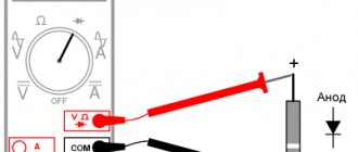
The measurement kit includes two wires with terminals and pointed probes:
- one black wire – “minus”, “ground”, “com” (common);
- the second red wire is positive or “measuring”.
It will be interesting➡ How to make a microphone from a phone with your own hands
The black probe is usually applied to the body of the electrical appliance (common busbar) or attached with a special clip - an “alligator clip”. The red probe is most often taken in the right hand and applied to different places in the circuit. The probes included in the digital multimeter are the same as those in the analog multimeter. Often the sockets are color-coded - red and black frames, so as not to accidentally confuse which probe is inserted where.
Sometimes the multimeter is a built-in part of another device, such as a digital clamp meter. Due to the need to be large, such devices have a large amount of free space in their housing, where the multimeter is built in.
Design, diagram and connection of an intermediate relay. Part 2
Hello, dear readers of the site sesaga.ru. We continue the topic of intermediate electromagnetic relay . In the first part of the article, we looked at the device, operating principle, electrical circuit of the relay and the designation of the relay on circuit diagrams, and in this part we will consider the main parameters and switching circuits of the relay .
Basic parameters of electromagnetic relays.
Main parameters
, which determine the normal operation of the relay and characterize the operational capabilities, are: 1. Sensitivity. 2. Triggering current (voltage). 3. Release current (voltage). 4. Holding current (voltage). 5. Safety factor. 6. Operating current (voltage). 7. Winding resistance. 8. Switching capacity. 9. Wear resistance and number of switchings. 10. Number of contact groups. 11. Time parameters: response time, release time, contact bounce time. 12. Type of load. 13. Switching frequency. 14. Electrical insulation.
All these parameters are given in detail in the technical specifications (TS), reference books or manuals for the use of the relay. However, we will consider only a few of them, which, as a rule, are used when repeating amateur radio designs.
1
.
The sensitivity of the relay
is determined by the minimum current power supplied to the relay winding and sufficient to drive the armature and switch the contacts. The sensitivity of different relays is not the same and depends on the design of the relay and the winding data of the coil. The lower the electrical current required to operate the relay, the more sensitive the relay. As a rule, the winding of a more sensitive relay contains a larger number of turns and has a higher resistance.
However, in the technical documentation the sensitivity parameter is not indicated, but is defined as the response power
(Рср) and is calculated from the winding resistance and operating current (voltage):
2
.
operating
current
(
voltage
) determines the sensitivity of the relay when the winding is supplied with
the minimum
current or voltage at which the relay must clearly operate and switch contacts.
And to hold them in the actuated position, operating
values of current or voltage are supplied to the winding.
The operating current or voltage is indicated in the technical documentation for normal conditions and is a control parameter for testing relays during their manufacture and is not an operating parameter.
3
.
release
current
(
voltage
) is given in the technical documentation for normal conditions and is not an operating parameter.
The relay is released (the contacts return to their original state) when decreases
to a value at which the armature and contacts return to their original position.
4. Operating current
(
voltage
)
of the winding
is indicated as a nominal value with two-sided tolerances, within which the operability of the relay is guaranteed.
Upper value
operating current or voltage is limited mainly by the heating temperature of the winding wire, and
the lower value
is determined by the reliability of the relay when the power source voltage decreases. When current or voltage is applied to the relay winding within the specified limits, the relay must operate clearly.
5
.
The switching capacity of
the relay contacts is characterized by the amount of power switched by the contacts.
In the technical documentation, the switched power is indicated by the upper
and
lower
range of switched currents and voltages, within which a certain number of switchings (operations) is guaranteed.
Lower limit of currents and voltages
, switched by contacts, is limited by the value of the contact resistance of the material from which the contacts are made. For most intermediate electromagnetic relays, the lower limit is the contact load with a current of 10 - 50 µA at a contact voltage of 10 - 50 mV.
Upper limit of currents and voltages
is the load of the contacts with the maximum switching current provided for in the technical documentation. The upper limit is limited by the heating temperature of the contacts, at which the mechanical strength of the contact materials decreases, which can lead to damage to the working surface.
We check the presence of voltage at the power contacts of the relay
If the relay clicks, it means that the control electrical circuit is working, the magnet is activated and the jumper moves. In this case, you need to check the presence of voltage at the power contacts of the relay. There is always voltage on one contact, and on the second it should appear when the relay is turned on. With the equipment connected through the relay being tested turned off, locate the power contact that is energized. To do this, insert the test lamp or multimeter probe into the corresponding socket of the mounting block, and the other end into the car body.
It will be interesting➡ Tesla coil (Transformer) self-assembly on your own
If there is no voltage at any power contact, it means that the power line is faulty and the relay has nothing to do with it either. The reasons for power line failure can be different, but first you should check the fuse. If there is voltage at one of the power contacts of the relay, then when the relay is turned on (the relay clicked, there is voltage at the control contacts), there should be voltage at the second power contact.
If the relay is turned on, and there is voltage on only one power contact, it means that current does not pass through the relay contact group. This usually happens due to burnt contacts of the jumper that closes the power line. It is easier to replace such a relay with a new one, since disassembling this structure and trying to clean the jumper is a rather difficult and unreliable task. Moreover, the cost of most relays is low.
Connecting intermediate relays.
The circuits for connecting intermediate relays are practically no different from the circuits for connecting contactors and magnetic starters. The only difference is the power of the switched load. If the contacts of intermediate relays are limited by the switching power of the contacts, which is about 5 A, then magnetic starters and contactors are capable of switching currents of more than 50 A and voltages of more than 1000 V.
Let's look at connecting a relay using simple diagrams as an example.
.
6.1. Circuit with normally open contact.
The circuit is powered by DC source GB1
voltage 12 V and consists of a push-button switch
SB1
, a relay coil
KL1
and an incandescent lamp
HL1
.
Standard automotive relays
Many improvements to the electrical equipment of a car include the use of power relays.
This article discusses the operating principle and several examples of relays used in cars. This article will be useful to all fans of tuning modifications regarding the electrical equipment of the car. Here are the main characteristics of domestic relays:
- Rated voltage: 12V
- Control current: no more than 0.2A
- Operation voltage: no less than 8.0V
- Release voltage: 1.5 - 5.0V
- Maximum switching current: 30A
- Control winding resistance: 80±10 Ohm
Versions of domestic relays:
- 90.3747-10 - plastic housing without mounting ear
- 90.3747 - plastic case with fastening eye
- 113.3747 - metal case with fastening eye
- 113.3747-10 - metal case without mounting ear
- 111.3747 - metal case with fastening eye
- 111.3747-10 - metal case without mounting ear.
The relay must be used in cases where switching of large load currents (20-40A) is required, and this is more than the control output produces (the winding of the relay control circuit usually consumes no more than 0.2A)
Relays with 4 and 5 contacts are available.
Power relays have winding contacts that control the operation of the power contacts (contacts 85 and 86), and the power contacts themselves (30, 87 and 87a).
The operating principle of a power relay is as follows. Voltage is applied to the relay's control contacts (winding), the winding attracts the relay's power contacts to each other, the relay operates and closes (or opens) the electrical circuit with its power contacts. If there is no voltage at the contacts of the control winding of the relay, contact number 30 is permanently closed to contact number 87a. If voltage is applied to the control winding of the relay, then contact number 30 is disconnected from contact number 87a and connected to contact number 87. One of the contacts, 87a or 87, may be missing. In this case, the relay works either only to close or to open the power circuit.
Some imported relays between the 85th and 86th contacts have quenching diodes or resistors, and sometimes both. These elements protect control circuits from overloads during operation of the relay contacts.
If the diode symbol is marked on the relay body, this means that when connecting such a relay, the polarity of the control contacts must be observed.
It is necessary to pay attention to the markings and arrangement of contacts on the relay, since some manufacturers produce relays with non-standard arrangement of contacts.
It should be noted that during prolonged operation of the relay in maximum load modes, the spark that jumps when switching contacts creates carbon deposits between these contacts, which is why the controlled device may not work or work incorrectly. In the place of poor contact, when current flows, excess heat is generated, the current in the power circuits increases, which entails heating of the place of bad contact in the connected circuit, and subsequently the melting of the plastic parts of the places where these contacts are attached occurs. The attachment points of the relay contacts melt, which leads to their displacement relative to their standard position, and due to the appearance of gaps between the contacts, sparking begins, and as a result of these processes, the contact area heats up even more.
Imported relays are considered more reliable; domestic relays are less sealed and wear-resistant.
When choosing a relay, you need to pay attention to the coating of the relay contacts and the connector where the relay is inserted. The most preferred are relays with tinned contacts.
Operating principle
Essentially, a relay is an electromagnet. When control voltage is applied to the coil, the rod attracts the armature, thus switching the circuit.
There are three types of relays:
- with normally closed contacts;
- with normally open;
- throwing over.
When a control signal is applied to a device with normally closed connectors, they open; if there is no signal, they close. For relays with open connectors, the opposite is true. There is voltage on the winding, the terminals close, but when there is no voltage, it opens.
In flip-over models there are two sets of connectors, one normally closed and the other normally open. They have a common terminal. When current is applied to the winding, the contacts switch from one position to another.
Relay electrical parameters
• Relay sensitivity - the ability to operate at a certain value of power supplied to the relay winding. Determined by the magnetomotive force (MF) of operation. If we compare different relays with each other, the most sensitive will be the one that operates at a lower MMF. In this case, the relay armature should be clearly attracted and the contacts of all groups should close/open.
In reference books, such a parameter as sensitivity is usually not given. It is calculated from the winding resistance and the operating current.
Pav = Iav2 * Rexchange = Uav2 / Roex
• Operating voltage (current). The technical conditions for specific types of relays establish the operating voltage (current), which, when powered, ensures the normal functioning of the relay. The technical documentation for a specific relay design indicates its value with tolerances. When voltage (current) is applied to the relay winding within the specified limits, it should function normally.
• Trigger voltage (current). This is one of the relay parameters that determines its sensitivity. This is the minimum voltage (current) at which the relay should operate normally, i.e. switch all your contacts. And to further hold the armature, the operating voltage (current) described in the previous paragraph must be applied to the relay winding.
In the technical documentation, this parameter is necessarily given for each relay version.
This parameter is a control parameter. It characterizes the stability of all structural elements and the stability of relay adjustment.
• Release voltage (current). It must be provided in the technical documentation for each relay version both for normal operating conditions and for conditions when various factors influence.
Releasing the relay is nothing more than returning the contacts to their original state. It occurs when the voltage (current) in the relay winding decreases to a level at which the armature can no longer be held in the actuated position and returns to its original state of the relay being turned off. All contacts also switch to their original state. Normally closed ones become closed, normally open ones become open.
There is such an indicator as the return rate. This is the ratio of the release current to the trip current. The value of this coefficient for different relays varies within very wide limits - from 0.1 to 0.98. Improving the return coefficient is achieved by bringing together the characteristics of the change in the electromagnetic force that creates the magnetic flux and the spring force that counteracts this flux. Also, improving the return coefficient can be achieved by reducing the stroke of the moving system and reducing friction in its axes.
• Winding resistance. Coil resistance is the active resistance of the relay coil with tolerances, measured at DC current. Must be given in the technical documentation and is valid for normal ambient temperature.
• Contact resistance of the electrical circuit. It consists of the resistance of the elements of the contact circuit and the resistance of the contacting surfaces. Measuring the resistance of contacting surfaces in a relay is very difficult. Therefore, it is assessed by the resistance of the entire contact circuit.
This parameter can change greatly both during the operation of the relay and during delivery/transportation, because depends on many factors.
Dirt getting on the relay contacts entails an increase in the voltage drop across the contacts. The consequence of this is increased heating of the contacts, which can completely damage the contact pair. Therefore, technical documentation usually indicates the contact resistance for the delivery period.
• Switching capacity of relay contacts. It is determined by the value of the power switched by the relay contacts performing a certain number of switchings.
It is important to understand that there is such a thing as contact corrosion. And it strongly depends on the switched power. But it manifests itself at currents of 100 mA or more. At lower currents, the main influence on the performance of the relay is exerted by mechanical wear of the moving system and contacts.
In those. documentation usually indicates the range of switched voltages and currents at which a specific number of switchings is guaranteed.
The maximum power that the relay is capable of switching is limited by the heating temperature of the contacts, at which the mechanical strength of the contact material decreases.
• Electrical insulation. Characterizes the electrical insulating properties of the relay. This is the ability of the relay insulation to withstand overvoltages (short-term and long-term) that inevitably arise during the operation of the equipment. The insulation of the relay is determined by the electrical strength of the gaps - air (intercontact) gaps and along the surface of the dielectric of the relay board. These intervals are used to judge the leakage currents of the relay.
Functionality check
On the body of each relay there is a diagram with contact numbers and control voltage rating. A rectangle with pins 85 and 86 means a coil. Therefore, when measuring winding parameters, you need to connect to them. Other pins numbered 30, 87 and 87a (88) are the switching key for the external circuit.
It is convenient to use a digital multimeter as a tester for regulator relays and any other electromagnetic relay. This is because it can measure current, voltage and resistance.
Since the performance of the device depends primarily on the health of the winding, the test begins with measuring the coil resistance. Its values range from several tens of ohms to several hundred ohms.
To do this, switch the multimeter to resistance measurement mode. We connect measuring probes to pins 85, 86 and take readings. If the resistance is within normal limits, then you need to check the condition of the controlled outputs.
In a relay with normally closed contacts 30 and 87, when measuring the resistance between them, the multimeter should show 0 Ohm. With normally open pins 30 and 87 the resistance between them should be infinity. When the control voltage is applied to the coil terminals 85 and 86, everything should change exactly the opposite.
How to test a relay
The electromagnetic relay can be checked with a conventional multimeter in ohmmeter mode. Since the relay coil winding has active resistance, it can be easily measured. The resistance of the relay winding can vary from several tens of ohms (Ω) to several kilo-ohms (kΩ). Typically, the lowest winding resistance is found in miniature relays that are rated at 3 volts. Relays rated at 48 volts have much higher winding resistance. This can be clearly seen from the table, which shows the parameters of the Bestar BS-115C series relay.
It will be interesting➡ We assemble a step-up transformer with our own hands
| Rated voltage (V, constant) | Winding resistance (Ω ±10%) | Rated current (mA) | Power consumption (mW) |
| 3 | 25 | 120 | 360 |
| 5 | 70 | 72 | |
| 6 | 100 | 60 | |
| 9 | 225 | 40 | |
| 12 | 400 | 30 | |
| 24 | 1600 | 15 | |
| 48 | 6400 | 7,5 |
Note that the power consumption of all types of relays in this series is the same and amounts to 360 mW. An electromagnetic relay is an electromechanical device. This is probably the biggest plus and at the same time a significant minus. With intensive use, any mechanical parts wear out and become unusable. In addition, the contacts of powerful relays must withstand enormous currents. Therefore, they are coated with precious metal alloys such as platinum (Pt), silver (Ag) and gold (Au). Because of this, high-quality relays are quite expensive. The positive qualities of electromagnetic relays include resistance to false alarms and electrostatic discharges.
Application in car
Most often motorists have to deal with switching devices. We are talking about the generator (starter) regulator relay. They remember it when the engine stops starting and it turns out that the battery is discharged. One of the reasons for this is a malfunction of the regulator.
On older cars, to maintain a constant voltage, a regulator was used, consisting of three devices - a voltage stabilizer, a current limiter and a reverse current relay. The regulator prevents the battery from overcharging, which prolongs its service life.
It can be built into the starter brush block or performed as a separate module. Its failure may or may not overcharge the battery. In the first case, streaks will be visible on the case, the electrolyte will begin to boil away, which will lead to a voltage drop below 12 volts. In the second, the values will initially be lower than acceptable. As a result, the engine will not start.
How to choose the right relay
So, let's start by providing information about the main technical characteristics of relays produced in our country:
- Rated voltage - 12V;
- Control current - no more than 0.2A;
- Operating voltage - not less than 8.0V;
- Release voltage - 1.5 - 5.0V;
- The highest switching current is 30A;
- Winding resistance - 80 Ohms.
Domestic relays are produced in the following types:
- 3747-10 — plastic case, no mounting eye;
- 3747 — plastic case, there is a fastening eye;
- 3747 — the body is made of metal with a fastening eye;
- 3747 - 10 - metal body, no mounting eye;
- 3747 - 10 - metal case, no mounting eye.
Resort to installing a new one. a more powerful relay is needed if you need to increase the permissible value of load currents (20-40A), which is noticeably more than the control output can provide (usually no more than 0.2 A).
On store shelves you can now find relays with 4 and 5 contacts.
As a rule, power relays have two pairs of contacts: power and control. Power contacts are designated by numbers 30, 87, 87a, while control contacts have indexes 85 and 86.
Video review of power relays for a car:
Checking the starter regulator
To check the starter regulator relay without removing it from the car, you can use a multimeter and test all the wires that go to it. To do this, they are first disconnected from the regulator. The multimeter is switched to resistance measurement mode, the disconnected wires are checked.
If everything is normal, then the conductors are returned to their place. The voltage at the battery terminals is measured with the engine off. The multimeter is switched to DC voltage measurement mode in the range from 0 to 20 Volts. The probes attach to the battery terminals. The device should show 12.2-12.7 V.
If 12 volts or lower, then it needs to be recharged.
Then the engine must be started and checked again with the same measurements. If the voltage is in the range of 13.2-14 V, then this is normal. We add engine speed to 2000 per minute and measure again. Normally, the multimeter should show between 13.6-14.2 V. We also add revolutions to 3500 per minute.
We take readings. They should not exceed 14.5 Volts. If the value does not change and remains 12.7 Volts, as when the engine is turned off, or even decreases, then the regulator relay is faulty. Therefore it needs to be replaced. If 14.5 Volts are exceeded, the regulator must also be changed.
Sometimes the question arises of how to test a relay with a multimeter if there is no access to the regulator. Then you need to remove it, and to check it you must have, in addition to the tester, a charger with a voltage regulator and a light bulb.
The following scheme is assembled from them. The charger is connected to the input terminals of the regulator, and the light bulb is connected to the output (thick) terminals. A multimeter monitors the voltage at the regulator input. By charging we change the voltage from 12 to 15 volts. The light should go out at 14.5 volts. If this does not happen, the regulator is faulty and must be replaced.
How to check the relay regulator
But all this does not directly indicate a malfunction of the voltage regulator. The relay is checked in a special way that is technically simple for every car enthusiast:
- We take a voltmeter and first measure the voltage at the battery terminals, having first started the engine. When the car is turned off, the norm on the battery is 12.7V, maybe a little less. At 12 volts, charging is required! This is an undercharge, the cause of which should be found as soon as possible.
- We start the car, set the device to 20 volts. We connect the probes of the meter to the battery terminals. We saw 13.2 -14 V, congratulations! Now increase the engine speed so that the tachometer shows 2000-2500. The norm will be 13.6-14.0 V.
- We accelerate to the maximum: 14.5 V is the limit with a working regulator! When, when gasping, the voltage remains within 12-12.7 V or exceeds 15 V, there is reason to believe that it is time to change the regulator.
But you need to know that sometimes such tricks also occur when the generator itself malfunctions. Replace the regulator and recheck. Is everything the same? Then generator repair awaits you. When the brush assembly is combined with the relay, dismantling the generator is also required!
How to check the relay regulator
Checking the solenoid relay
When the battery is charged, but the engine does not start, you need to check the starter.
If the generator spins but the engine does not, then in such cases it is necessary to check the solenoid relay of the electric motor and the bendix. To do this, you need to remove the starter. After this, all contacts are cleaned, and the resistance of the relay winding is measured with a multimeter.
If the value is infinity, then the winding has burned out. In this case, it is necessary to rewind the coil or replace it. The device shows several tens of ohms, which means the winding is intact.
Then its performance is checked. The positive terminal of the battery is connected to the corresponding relay terminal using the cigarette lighter. And the minus is connected to the starter housing. A click should be heard, then the device is working properly, otherwise it needs to be disassembled and the mechanical part checked.
Preparing for the test
Before you check the relay for functionality with a multimeter, you need to understand what needs to be checked. To do this, you should use a datasheet.
They are looked for by the markings on the body. Just type the value into a search engine and you will find the required document.
Sometimes the relay diagram is printed directly on the body, which is more convenient. In this case, you won’t need to Google anything.
The contacts in the diagram are shown as dots connected to the winding. Switches are marked with dotted markers.
How to check a solid-state relay with a multimeter if there are no datasheets or circuit diagrams? You will have to visually determine the necessary contacts:
- Inspection. Usually the control contacts are a little lighter than the others; this marker can be used to guide you. In the diagram the contacts look like this.
- Studying the board. If the relay is soldered in, then you can find the supply tracks on the PCB. In addition, the manufacturer often signs the contacts.
- Search for board diagram. Another option is to look for this board with components included. In block diagrams, components can be labeled.
What is a relay and how to determine its contacts is clear, all that remains is to prepare a multimeter. The only thing you need to do is check the battery.
It must be well charged, otherwise the tester will “start lying.”