A properly organized electrical wiring system is an important technological characteristic of working conditions in various sectors of the national economy and industry, from small welding production to energy enterprises. Not only the stability of equipment and communications operation, but also the safety of personnel depends on the quality of the installation of power supply lines. Busbar trunking helps to organize reliable wiring that meets technical standards, the installation of which increases the design capabilities when laying cables, and also provides a high degree of their physical protection from external threats.
Preparation for installation work
By the time technical operations are completed, the execution team must have a work plan with a design solution, which describes the assembly and placement of equipment. In particular, the design documentation includes:
- Assembly drawings. The type of connection, characteristics of fastening materials, layout methods and options for reinforcing the housing are indicated.
- Equipment parameters. Since busbar trunking designs vary, a plan must first be drawn up for pairing the housing parts with the load-bearing surfaces of the installation site. For example, models with a solid structure can be mounted directly to the wall using guide profiles, and some perforated versions of the busbar trunking are also mounted on suspended frames.
- Data on the required physical strength, tools and mechanisms to perform assembly and installation activities.
Regarding the preparation of busbar trunking components, the following operations are performed:
- Checking the condition of parts for flaws and defects.
- Checking the compliance of equipment characteristics with design parameters.
- Checking the completeness.
- Delivery of components to a temporary storage site before assembly or directly to the installation site.
In terms of the direct organization of the installation process, workplaces are prepared, tools and necessary devices are checked at the site.
Types of busbar trunking
Next, we will consider the classification of busbars according to the method of application.
Distribution and trunk busbar
The distribution (main) busbar is designed to transmit electricity from the main switchboard (MAS) to large consumers, distribution and group switchboards. Also, using a busbar, electricity is transferred from the transformer to the main switchboard (ASU).
Direct transmission section of busbar trunking
Direct distribution section
The distribution section of the busbar can contain up to six (three on each side) sockets for connecting power take-off boxes. Structurally, the sockets are implemented in such a way that connecting and disconnecting power take-off boxes is possible without removing the voltage from the busbar. This ensures improved continuity of power supply and improved performance of the power supply circuit. Also, the power take-off box can be installed at the junction of busbar trunking sections. But to install and dismantle it, it is necessary to remove the voltage from the busbar.
The maximum rating of boxes installed in a busbar trunking socket is 630 A. Boxes installed at the junction of busbar trunking sections have a rating of up to 1250 A.
Direct transmission sections for communication “Transformer - main switchboard (ASU)”, as well as in sections of the line where connecting consumers and “removing” power is not required. There is a temptation to make the busbar route only from distribution sections, but they are noticeably more expensive than transmission sections, so the busbar route is made from transmission sections, and direct distribution sections are installed at consumer locations.
Trolley busbar
Trolley busbars are used to supply power to beam cranes, overhead cranes, hoists and other moving equipment. The U-shaped busbar trunking body is made of galvanized steel or plastic. Tires are located inside. A current collector trolley is inserted inside the busbar (hence the name of the busbar - trolley - trolley in English).
Lighting busbar
Lighting busbar is a general name for track busbars and low-power distribution busbars.
Distribution busbar for lighting networks
Low power distribution busbar trunking (rated currents 25 A, 32 A, 40 A) is mainly used to build lighting networks, so it is often called lighting busbar trunking.
The busbar trunking body is made of galvanized steel. The housing is used as a PE conductor. Busbars (from two to six conductors) are located inside the housing. Double lighting busbars are also manufactured.
On both sides of the case there are sockets for connecting lamps or other equipment. Busbars are equipped with special plug connectors.
The busbar is a self-supporting element, which allows lighting fixtures to be mounted directly on it. It is a good alternative to the “cable tray + cable” system.
In addition to building lighting networks, it is used to connect low-power equipment on conveyors, as well as in garment factories.
Lighting busbar for track lights
Lighting busbar for track luminaires is used for lighting residential and commercial premises, where flexibility of lighting solutions is needed. The body is made of plastic, galvanized steel or extruded aluminum. Copper bars are located inside the housing. The design is similar to a trolley busbar, with the only difference being that track lights are installed instead of a trolley-collector.
Track lights on the busbar trunking are installed in the required place and can be easily moved along the entire busbar trunking line. An almost ideal option for shops, boutiques and exhibition spaces, where you need to highlight some area and the exposure may change frequently.
Busbar trunking installation technology
The most difficult type of structure to install, it houses power cables operating under high voltage. For example, among the features of the installation of busbars and conductors above 1000V, one can highlight the need to make connections by welding, connecting special equipment for lifting assembly blocks and preparing support structures to hold channel elements.
Work begins with the arrangement of sections into modular blocks with an average length of 9 to 12 m. At this stage, the corners and nodes of the branches are performed by resistance welding in an argon environment using semi-automatic machines. The complexity of this operation lies in the fact that this type of welding places stringent demands on the working environment. For example, in rooms with a high fire hazard class and in dusty areas, this connection method is excluded, so assembly is carried out in advance at other sites.
When installing 1000 V and 1200 V busbars, bolt clamps are used when it is necessary to create detachable connections. Fixation is usually carried out with bolts of M8 and M10 format along the channel guides, in which mounting points for integrating hardware must initially be provided. Spring washers and side metal covers are installed along with the bolts.
Installing luminaires on the track and connecting them to the network
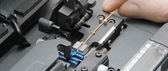
Upon completion of the installation of the busbar and connection to the electrical network, we install track lights using specialized adapters with fixing clips.
- closed tracks 220 V
- first set the clamp ring on the ice lamp to the OFF position. Then we place the lamp in the track and turn the handle 90 degrees (ON) to fix and release the contact plates; - magnetic low-voltage tracks
- insert the ice-lamp until it is fixed with a magnet. We turn the lock handle to extend the plates in contact with the conductive busbars.
Next, we move the LED lamps along the track rail to the design locations, adjust the angle of inclination to direct the luminous flux to the required area.
The track system is a flexible solution that allows you to change the configuration of the location of track lights during everyday use. A couple of minutes are enough to move several lighting fixtures to new places and illuminate the necessary locations.
If you have any questions, contact the Ledrus manager for prompt advice. Our specialists will help you choose the complete track system and LED track lights with the required parameters.
Distribution busbar installation technology
Support structures are pre-installed, which are subsequently used according to the principle of load-bearing structures. At the next stage, the same arrangement of sections with blocks is performed using fasteners.
When installing supporting infrastructure, it is recommended to maintain a distance between supporting structures of 3-4 m, but no more. Moreover, the height should vary within 2.5-5 m depending on the conditions in the room and the design features of the wire itself.
For joining, screw fastenings are used that close the coupling halves. At the assembly stage, the connecting clamps must be in a weakened state so as not to deform the structure when performing hinged fasteners. Subsequently, the fastening force is brought to an optimal state with clamping values of 200 N or 21 kg. Also, the technology for installing distribution-type busbars provides for monitoring the joint by checking the fit of the protrusions. The coupling halves must fit into the fixing holes of the modular sections. The configuration of their placement is pre-calculated in the wiring diagram.
Despite the cumbersome design of distribution channels, they provide wide possibilities in terms of placement options. Rigid fixation, in particular, can be performed to specially constructed supports, columns or to wall surfaces. With a small mass, it is also possible to suspend the channel in spans.
What is a busbar
The device consists of conductors, which may or may not be insulated, insulators and devices with the help of which the transmission and distribution of electrical energy is carried out in premises and on the territory.
Busbar trunking models
The most common busbars are for installations with voltages up to 1 kV, which are complete trunk or distribution lines.
Main busbar
The design of the busbar trunking can be different depending on the shape of the busbars, their size, location, insulators used, and the method of protection from adverse influences.
Busbar installation for lighting
The busbar is a package of busbars housed in a rigid casing. In cross-section, the devices look like an I-beam or a rectangle (less often, an oval). Busbars mounted on insulators can be copper or aluminum.
Copper busbar section
The most common are models with flat aluminum tires.
Busbar composition
Most often, closed (having a metal or polymer housing) devices are used in low-voltage networks.
Polymer busbar
The busbar consists of segments with different configurations. These sections can be made in corner, straight, branch or other form.
In addition to them, the package may include: transition elements that allow connecting busbars and other components, branch boxes designed for connection to the busbar, fastening systems for installing equipment on various bases and other components.
Busbar composition
Depending on the purpose, the use of trunk, distribution, trolley and lighting models of busbars is practiced.
Trolley busbar installation technology
The features of conductive channels of this type include their ability to ensure the movement of suspended electrical equipment, such as machine tools, crane units, roller mechanisms, etc. In essence, this is a monorail system based on rigid steel frames with channels for placing power electrical wiring.
Installation is carried out using scaffolding or special lifts on prepared mounting structures. A rail track system must be organized in which free passage of the target mechanism along the address contours is ensured. I-beams serve as the load-bearing base. They are mounted to ceiling or wall surfaces, which, in principle, can withstand heavy loads. The installation instructions for this type of busbar indicate that when fixing, the minimum distance between the mounting points of the brackets should be no more than 3 m if straight installation is intended. In areas with turns or curved sections, the distance between fasteners should be no more than 1.5 m.
During installation, special attention is paid to the technical design of servicing mechanics such as carriages and rollers. Firstly, the lines of their movement must be clean and smooth - without protrusions, burrs and other defects. Secondly, the external non-working surfaces with drive communications and the rear part of the movable mechanics are additionally covered during the installation of the busbar trunking with complete covers and couplings, for which the free space is also preliminarily calculated.
Why install a busbar
Our craftsmen install turnkey busbars: from design to commissioning. We will help you pass the necessary checks when putting objects into operation. Installation of track busbar trunking is a measure that allows you to increase the usefulness and safety of electrical wiring.
This power transmission system has 5 advantages over classical wiring:
- Compact design. In appearance, it is a compact box that can be hidden under a suspended or suspended ceiling.
- High speed of installation and dismantling. The power line can be easily moved to another location.
- Increased design safety: high degree of protection - from ip55 and higher. Low level of electromagnetic radiation.
- Minimal energy losses and savings due to lower resistance.
- Long service life: 20-30 years without the need for systematic maintenance.
Busbar for luminaires and lamps is a solution that reduces the risk of accidents and provides improved safety for personnel.
Connecting equipment to the track busbar
Special models of busbars with a track connection system are designed for the installation of lighting devices. They are distinguished by an optimized and compact system of suspensions with transitions, due to which it is possible to design conductors of any shape and configuration. Installation and connection of track lights on the busbar are carried out in the following sequence:
- The wire base is secured by installing screws into the holes made, gripping the base panel, or using a hanging bracket on cables.
- The terminal block is installed, through which the track lamp is subsequently connected.
- If the block is not provided for in the design, it must be integrated using a special module that is suitable in format to the connecting fittings of the busbar.
- The connection is made according to the standard scheme - the gripping screws in the well are unscrewed, after which the wire strands are inserted and the fasteners are returned to their previous state.
By connecting the track light to the busbar in one section, you can lay its line along the following blocks of the structure to the point of entry into the supply transformer. One central connector allows you to create branched networks of power supply to lamps distributed along long wire rails. Also, most track designs provide for the possibility of universally increasing the length of the channel, which is done using special connectors.
Installation and connection of busbar trunking
If the standard length of the busbar does not allow you to assemble a precisely calculated design of a track lighting installation, then the track can be cut into sections of the required length. To do this, you can use a regular hacksaw for metal.
Next, to install the busbar, we carry out the following activities:
- When mounting directly to the ceiling or wall, you must drill holes in the busbar.
- To create a suspended track installation, you will need a special cable and bracket.
- A plug is installed on one side of the busbar trunking through which the power supply will not be routed.
- A terminal block must be installed on the other side. If it is not installed initially, then the block must be positioned next to the end of the track so that the marking stripes coincide and then carefully insert it into the busbar. The connector and track will be connected.
- Next, the electrical wire is connected. To do this, remove the cover from the connector, unscrew the screws with a screwdriver, and then insert the wire strands into the resulting holes.
- After connecting the power supply, you need to tighten the locking screw and finally secure the connection.
Features of installation of open busbars
Almost all types of busbar trunking are made in two versions - with an open and closed loop system. The first option is a lightweight design without external protection. It is recommended to use such equipment in places where there are no aggressive external environments.
Installation is carried out according to a simplified scheme - using bolted connections, suspension cables or mounting plates to the surfaces of communication shafts. However, after installing open busbars, it is necessary to carry out special insulation of the cables. For example, areas of a bus where exposed insulation is used should be covered with asbestos or similar fire-resistant material, which will also prevent sparks from entering the wiring. External closing covers and panels are not used in such structures.
How to install a busbar without tearing the fabric
First, you need to figure out how to install a track lamp if you use a mounting fastened in advance above the canvas. This is a simple solution that can be done even with minimal construction experience. The instructions look like this:
- The size of the busbar and its location are determined. First, a simple diagram with dimensions is drawn up. Then you need to mark the surface of the ceiling to indicate the position of the future structure.
- The wiring is laid in advance; it is better to use a flexible cable with copper conductors. The cross-section is selected according to the total power of the equipment; for concrete floors, special fasteners are used so that the wire does not sag and is held securely. Sufficient margin is left to connect the track.
- For installation, a wooden block or strip of suitable length is best suited. To set the optimal position, it is easier to use drywall hangers for mounting to the ceiling, since they can be bent as needed. The hangers are fixed with dowels to the concrete, and screwed to the block with self-tapping screws.
Metal corners are also suitable for fixing the timber. - After stretching the ceiling, you must first remove the wire; to do this, glue a plastic ring of a suitable size, inside of which a hole is cut.
Rings and glue for stretch ceilings. - Next, you need to glue washers through which you can screw in self-tapping screws to secure the magnetic busbar. Then the contacts are connected through a block or by soldering and the operation of the system is checked.
The overhead option is the easiest to implement.
By the way!
If you don’t have washers for the screws, you can stick pieces of tape on the ceiling and screw the fasteners through them.
Features of installation of closed busbars
These are full-size prefabricated modular shafts that cover the electrical route from all sides. This option can be used in areas of increased external loads. The wiring itself at the first level of insulation is covered with a multilayer shell, which prevents the risks of mechanical stress and electromagnetic influence. A metal case made of aluminum or steel alloy is mounted outside. Reinforced mounting structures with anchor fixation can be used as fastenings for closed type busbars. Heavy enclosures are mounted using brackets on frames and profile mounting components. The surfaces of permanent structures, walls, ceilings and partitions are usually used as the basis for fastening. The operational features of a metal closed box include the fact that it acts as a grounding circuit that can be connected to the main electrical protection channels. In open-type systems, this function is already performed by special metal rods as part of the busbar trunking.
System overview
A track lamp is a lighting device fixed on a busbar, the contacts of which go to the conductive busbars of the track. Among its main advantages are:
- relatively simple and quick installation with connection;
- the ability to quickly replace or install the lamp in another location;
- possibility of connection to independent electrical groups.
The disadvantages of such lighting devices include their rather high cost.
A track lighting system is considered an excellent option, allowing not only to make the interior stylish, but also to minimize “digging” in wires. Its design has a minimalistic design, pleasing with various color shades.
The track light can be attached in several ways. The most common is installation on a wall or installation on a ceiling surface (for example, on a suspended ceiling).
Thanks to cables or chains, the track system can also be installed on a suspended ceiling (as shown in the photo below). As an alternative, you can install such lighting under the ceiling to illuminate it from the inside.
A pleasant nuance is that the track lamp can be installed even after the finishing stage of the repair work is completed. This does not require the services of specialists at all - you can connect the system yourself.
By the way, the price for the work of a master who will install the lamps on the tracks will be no less than 900 rubles per linear meter. So isn’t it better to save money and install and connect to the network yourself?
Equipment for assembly and installation of busbar trunking
The complex of installation activities provides for the implementation of seemingly typical, but still diverse technical operations. At each stage of the work, a certain group of tools and equipment is used. In particular, the following tools and devices are used:
- Manual installation tool. A basic set of tools, including screwdrivers, hammers, pliers and other tools that will be needed to work with fasteners during the wire assembly process.
- Power tools. To create holes, cut excess busbars and serial tightening of hardware, you will need a drill/driver, jigsaw, angle grinder, welding equipment, hammer drill, etc.
- Equipment for installation of the structure. This is additional equipment for the installation of busbar trunking, through which the structure can be lifted and suspended. In this capacity, traverses, grabs, winch mechanisms, lifts, crane manipulators, etc. are used.
- Measuring instruments. This tool is used to check the condition of the electrical infrastructure of a busbar trunking. We are talking about multimeters, testers, ammeters and other devices that measure certain wiring indicators.
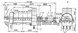
Installation of open busbars
Fig 7
Open busbars are installed in the following sequence. In accordance with the markings, metal structures with insulators are installed, busbars are laid and secured to the insulators, then the busbars are connected to current sources and to electrical receivers.
Metal structures for busbar trunking are manufactured at the MEZ, insulators, busbar holders or cleats are installed on them, delivered to installation sites and secured by shooting, driving in or welding to embedded parts.
Tire strips are also prepared using the industrial method at the Mining Plant, where they are processed, bent and joined into strands. The permanent connection of the tires is made by welding, and the detachable connection is made by bolts. Their ends are cleaned on tire milling or sharpening machines or using various cleaning devices. For a small amount of work, tires can be cleaned with brute files under a layer of technical petroleum jelly, which after stripping is removed and replaced with clean petroleum jelly. After this, the tires are pre-painted, labeled, rolled into coils or wound onto inventory cassettes and delivered to the installation site.
After straightening, the busbars are installed in busbar holders or directly on insulators and the fastening bolts are pre-tightened. In the mounted busbar trunking, the busbars must be straight and even, without local approaches in the span between the fastening points. For this purpose, a tensioning device of the UN type is mounted at one of the ends of the busbar trunking, with the help of which the tires are tensioned and finally secured in the busbar holders. The tensioner is used during the subsequent operation of the busbar trunking to tension tires that lengthen over time due to the fluidity of aluminum.
Descents from the busbar to electrical receivers are made with cables or wires laid in pipes and metal hoses. The busbar is passed through the wall and ceiling through a collapsible insulation board that covers the opening in the wall.
After completing the installation work, the tires and bus holders are re-painted: phase A - yellow, phase B - green and phase C - red. In DC busbars, the positive busbar is colored red, and the negative busbar is colored blue. The paint layer also protects the tires from corrosion and promotes better cooling (the heat transfer of painted tires is much higher). If the busbar phase consists of one busbar, it is painted on all sides, and in packages only the outer surfaces of the busbars are painted. Do not paint bolted connections, as well as areas provided for applying portable grounding connections (these areas are bordered along the edges with stripes applied with black paint). In busbars, as well as in switchgears, the red bus is lower than the others and further from the wall, the green bus is in the middle.
Installation of trolley busbars
Fig 8
Trolley lines serve to power movable lifting and transport mechanisms (cranes, crane beams, electric hoists, etc.) and are three-phase conductors laid along crane tracks. Angular steel busbars mounted on special trolley insulators are used as current-carrying contact conductors.
Trolley busbars are used to install all types of equipment, including cranes, monorails, hoists, tools, machines, automated storage and retrieval systems and many other mobile devices.
For the installation of open trolley lines, standardized brackets with insulators and trolley holders installed on them are used. The brackets are attached directly to the walls or to the crane beams with bolts or by welding to embedded parts (if the crane beams are steel). To compensate for thermal expansion of busbars between individual sections of the highway when installing long sections (30 m or more), busbar compensators are used. The presence of voltage on the trolley line is determined by the trolley traffic light, which consists of three signal lamps mounted on a steel stand and protected by colored glass. A junction box is used to connect the traffic light to the trolleys. Signal lamps are not required to create high illumination, therefore, to increase their service life, a 300 Ohm resistor is connected in series with each lamp.
Installation of trolley lines begins after the construction part of the building is completely finished and the crane beams and rails are installed. Trolley blocks are prepared in the oil extraction plant using templates or on conductors. The conductor for assembling trolleys consists of a welded steel frame, which rests on subframes welded to it. Clamps are mounted on the frame to hold the elements of the block during its assembly. Templates are clamped in the intermediate clamps, according to which the block is assembled, and with the help of the middle and outer clamps the structures used for mounting the trolley block and for securing the block to the wall when installing the main line are secured. After securing the elements, the block is assembled and the trolleys are installed.
The finished unit is placed in a special cassette, delivered to the installation site, winched to the required height and mounted from aerial platforms, installation trolleys, and hydraulic lifts. When installing trolleys using an installation trolley, the trolley with a tool storage box is secured to the metal structures of the overhead crane. An electric winch for lifting blocks and a welding transformer are installed on a bracket above it.
Trolley busbars of the ShTM series are designed to power lifting and transport mechanisms (single-girder cranes, electric hoists, overhead crane beams and transfer trolleys) and are used in industrial premises with a normal environment. They can also be used to power electrified tools at a voltage of 220/380 V. The set of busbar trunkings includes straight (750, 1000, 1500 and 3000 mm long), corner and end sections. The straight section of the trolley busbar is a steel box with a solid slot at the bottom for the passage of the current collection carriage, which moves along the busbar when the lifting mechanism moves. Inside the box, insulators are fixed every 300 mm in length, holding four (three phase and neutral) copper trolleys. Couplings are used to connect busbar sections and insert current collector carriages into them.
Corner sections are designed in the same way as straight ones, but their frame is bent at an angle of 45 or 90° with a radius of curvature of 800, 1200 and 1400 mm. They allow you to assemble a busbar with a wide variety of route shapes (rotated by 45 or 90°).
Current collection carriages are installed on an electric hoist or crane beam on a special drive bracket. The carriage is a metal trolley with four guide rollers. Four blocks of current-collecting contacts are mounted on it, each of which includes two copper-graphite brushes. The cart can be equipped with circuit breakers, fuses or a terminal block.
The use of trolley busbars instead of open trolleys significantly reduces metal consumption and labor costs during installation work.
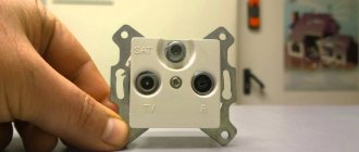
INTRODUCTORY SECTIONS
Input sections are part of the busbar and are designed for connecting supply wires or cables.
Input sections can be installed both in the middle and at the end of the line. In the latter case, the open end of the section is closed with an end cap. Wires or cables are brought in from the top or bottom of the section and connected to terminals rated to carry double the current rating.
Depending on the direction of cable entry (top or bottom), the contact clamps are rearranged accordingly. The inlet section is a straight section equipped with an inlet box that can be placed on both sides of the sections. The supply wires are connected to the busbars using contact corners.
Table 7.
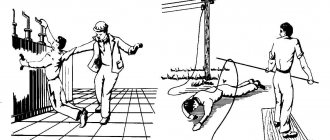
Safety precautions when installing busbar trunking
During the installation process, the general requirements of safety rules when performing electrical installation work must be observed, as well as special standards related to adjustment activities in relation to conductive modules. These include the following:
- It is prohibited to use busbar trunking structures as load-bearing elements or scaffolding.
- During installation, it is prohibited for third parties to be in the assembly and fixation area of the busbar trunking until the rigid fastening is completed.
- When organizing technical conditions for performing fastening and connecting operations at height, you cannot use devices and devices that are not intended for safety purposes.
- Special safety requirements when installing busbars apply to welding operations. In particular, such operations should only be carried out by suitably qualified installers. In the room where welding is performed, flammable objects and materials must be isolated.
Power supply to the track system
For safety reasons, be sure to turn off the power in the area where you will be working. Before you begin installing your track lighting, find your circuit breaker. Your light switch may be in your hallway, closet or closet. This is a metal or plastic box, usually placed on the wall. Turn off the power to the ceiling fixture where you want to install track lighting. After turning off the power, try turning on the light in the area where you will be working, just to make sure you pressed the correct switch. If you don't know which switch controls the light in the room where you will be working, find someone to help you. Turn off the switches one at a time while your helper monitors the lights to make sure they don't go out. If the switch is far from the light, use cell phones to communicate. After which you can begin dismantling the old lighting source. Remove the old lamp and expose the power supply wires. Be careful when unscrewing the old light fixture. It may be heavy or bulky. Once you remove it, you will see a box in the ceiling containing wires. This is the power supply to the lamp. After removing the old light fixture, put it in a safe place where it will not be underfoot. Connect these wires to the busbar trunking feeder adapter. The end power adapter usually comes with the track and is its end extension. Use self-tapping screws to attach the busbar to the ceiling. When installed correctly, the power end adapter completely covers the technical hole from which the power wires exit.