In the operation of electrical circuits, situations constantly arise when it is necessary to turn on or off any installations and equipment from a distance. To solve these problems, electromagnetic contactors operating with different types of currents are widely used. In the normal operating mode of switching devices, such operations are expected to be performed frequently - approximately 1500 per hour. The design and operating principle of contactors allows them to be actively used to control high-power motors installed on electric locomotives, trams, trolleybuses, elevators and other machinery and equipment.
Components and components of a switching device
There are devices with other types of drives - hydraulic and pneumatic. However, electromagnetic contactors are the main ones because they are more versatile, efficient and wear-resistant.
The operation of electromagnetic type devices is carried out due to the interaction of all units, parts and components that make up the whole device.
Each AC and DC contactor consists of:
- Main (main) contacts. They close and open a high voltage circuit and are capable of operating for a long time under the influence of a current with a set rating. Contact groups can withstand on-off cycles in large quantities and with high frequency. When the contacts return to their normal position, current stops flowing through the retractor coil, and the mechanical latches go into a free state. The design of the main contact group can be lever-type, with a moving system of turns, or bridge-type - with a straight stroke.
- The contactor device includes a chamber for extinguishing the electric arc. Used in DC devices. The design of this element has slots located longitudinally, and direct damping is carried out by the action of transverse magnetic fields. The excitation of such fields is carried out using an arc suppression coil, connected to a series circuit along with contacts.
- Arc extinguishing system. It is used by an AC contactor. With its participation, the electric arc that occurs at the moment when the main contacts open is extinguished. The configuration of this design and extinction methods are selected according to the operating mode and current parameters in a particular circuit. A special lattice structure is installed inside the chamber, when it hits it, a large arc is divided into several small fragments and goes out completely when the current passes the zero mark.
- Parts used in an electromagnetic circuit. This includes the magnetic core, armature and coil, and mounting materials. This circuit allows you to control the device from a distance, turn the circuit on and off. It can be configured to perform certain operations - turn on the anchor and keep it on, or just turn on the anchor. There is a special latch to maintain the closed position. De-energizing the coil and completely turning off the contactor is carried out by the own weight of the entire system, but, as a rule, structures consisting of tripping springs are used for this purpose.
- Additional contacts (auxiliary). Designed for switching in circuits that control the device, and in areas with blocking and signaling functions. Current can pass through these contacts for quite a long time, but not higher than 20 A, and switching off occurs at a current strength of no higher than 5 A. The contacts can be of making or breaking action, many of them have a bridge design.
What is a contactor?
The contactor is an electromechanical executive mechanism made in the form of a block in which high-speed contact groups are located. The contactor can function as an independent device or be used in the design of other equipment or in a control and protection system for an electrified facility. The contactor system is a switching unit that supports remote control and can be used for frequent switching of electrical circuits operating under normal operating conditions. To close / open contacts, electromagnetic drives are mainly used, which drive the actuator. Unlike a relay system, which can also close or open contacts, a contactor breaks the electrical circuit simultaneously in several places at once, while a relay does this only in one place.
Operating principle of contactors
The main part of the contactor that immediately catches your eye is the coil of wires. On the inside there is a core connected mechanically to the contacts. These elements close or open an electrical circuit, creating a flow or, conversely, stopping the flow of current. A copper or steel frame shell gives the coil the necessary rigidity and contributes to more efficient cooling of the device parts.
The operating principle of the contactor involves certain actions of the opposite nature. After voltage is applied to the coil, a magnetic field arises, under the influence of which the core begins to move from bottom to top. As a result, the circuit is closed and a current is generated that drives the connected electrical equipment. When the movement of electricity stops, the core, under the influence of the spring system, returns to its original state. As a result, the circuit opens and the electrical equipment turns off.
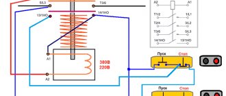
The on/off function of the contactor device consists of the operation of a special push-button mini-device with START (black) and STOP (red) buttons. When you press on each of them, the contacts close and open, respectively. The potential is applied to the coil and the power contacts are closed. They remain on even after the start button is returned to its original state. This function is carried out using auxiliary contact blocks.
The principle of operation of the contactor also lies in the action of the switching circuit, where two circuits are involved. The first of them is the control one, which transmits power to the coil. After closing the contacts, a high-voltage circuit comes into operation, the current in which is much higher than in the control circuit.
Contactors and magnetic starters
To bookmarks
Introduction
At the beginning of this article, I would like to immediately determine what the difference is between a contactor and a magnetic starter, since this question often baffles even the most experienced electrical specialists, while many believe that the difference between them lies in their design, overall dimensions or the value of the switched (rated) current, but this is not so. GOST 30011.4.1-96 will help us understand this issue, which provides the following definitions:
A contactor is a switching device with a single rest position, not manually operated, capable of switching on, carrying and breaking currents under normal circuit conditions, including during operating overloads.
A starter is a combination of all the switching devices needed to start and stop the motor, with overload protection.
As follows from the definitions above, a contactor is a device designed to switch (turn on/off) any loads, i.e. any loads, while starters are a set of devices designed to control a specific electric motor, as well as providing its protection against overloads, while the contactors themselves are part of the starters:
As you can see in the picture above, the starter includes: a contactor - to turn the electric motor on and off, a thermal relay - to protect the electric motor from overloads, buttons - to control the contactor, all of the above devices are placed in a common housing.
Also, according to the same GOST 30011.4.1-96, starters come in the following types:
Direct-acting starter - A starter that supplies mains voltage to the motor terminals in a single step. Reversing starter - A starter designed to change the direction of rotation of a motor by switching its supply connections without necessarily stopping the motor. Bidirectional Starter - A starter designed to change the direction of rotation of a motor by switching its supply connections only when the motor is stopped.
Thus, a direct-acting starter is designed to start, stop and protect the electric motor, while a reversing starter, in addition to all of the above, allows you to change the direction of rotation of the motor.
As you can see in the picture above, the reversible magnetic starter includes two contactors; switching between them changes the phase sequence, which leads to a change in the direction of rotation of the electric motor. (For more information about changing the direction of rotation of the electric motor and the operating diagram of the reversing starter, see here.)
There are also so-called modular contactors - these are compact contactors designed for installation on a DIN rail, otherwise their design and operating principle are the same as those of conventional contactors.
Now, having understood the concepts of contactor and starter, let’s begin to study the principle of their operation.
Design and principle of operation of the contactor
As can be seen in the picture above, an electromagnetic contactor consists of the following main elements: a magnetic circuit consisting, in turn, of moving and stationary parts, an electric coil, power contacts designed to turn on and off the load, which include moving contacts that are attached to the moving parts of the magnetic circuit and fixed contacts that are attached to the upper part of the contactor body, block contacts intended for use in control circuits, as well as a spring that ensures that the power contacts are maintained in an open state.
The contactor is controlled by applying voltage to an electric coil; when an electric current passes through it, an electromagnetic field is created flowing through the magnetic circuit, while the stationary part of the magnetic circuit together with the electric coil work as an electromagnet which, as can be seen in Fig. 2 above, overcoming the resistance of the spring, attracts the upper moving part of the magnetic circuit with moving contacts attached to it, thus closing the power contacts; when the voltage is removed from the contactor coil, the electromagnetic field disappears, ceasing to attract the moving part of the magnetic circuit, which, under the influence of a spring, returns to its original position, opening the power contacts.
Most modern contactors include only one block contact, but some control circuits require more of them; in this case, an additional attachment with several block contacts is installed on the magnetic starter:
As you can see in the picture above, this attachment (contact block) is installed on the upper part of the contactor connecting to its movable power contacts.
Note: See here for control diagrams for contactors (magnetic starters).
Selection of contactors (magnetic starters) and their characteristics.
The selection of contactors and magnetic starters is carried out according to their following technical characteristics:
1) The required category of application is determined by the type of switched load
In accordance with GOST 12434-83 and GOST R 50030.4.1-2002, there are the following categories (areas) of application of contactors (starters):
2) By rated current
Rated current is one of the main characteristics that determines the maximum current that the contactor can withstand for a long time, as well as ensure its switching (on/off).
The rated current of a starter (contactor) for an electric motor can be calculated using our online calculator or using the method given below.
There are the following standard values of rated currents of contactors (starters), in Amperes:
6.3; 10; 16; 25; 40; 63; 80; 100; 125; 160; 250; 400; 500 Ampere
Note: Modular contactors are available for rated currents up to 100 Amps.
Often, contactors and magnetic starters, depending on their rated current, are conventionally divided into the following values (from zero to seventh value):
The rated current of the starter for controlling the electric motor can be selected based on its power according to the following table:
You can also calculate the starter current yourself using the following method:
The rated current of the starter must be greater than or equal to the rated current of the motor:
I no. MP ⩾ I nom. engine
The rated current of the motor can be found from its passport data, or calculated using the formula:
Inom=P/√3Ucosφη
Where:
- P - Rated power of the electric motor (taken from the motor’s passport data or determined by calculation);
- U - Rated voltage (voltage to which the electric motor is connected);
- cosφ - Power factor - the ratio of active power to total power (taken from 0.75 to 0.9 depending on the power of the electric motor);
- η - Efficiency factor - the ratio of the electrical power consumed by the electric motor from the network to the mechanical power on the motor shaft (taken from 0.7 to 0.85 depending on the power of the electric motor);
You can also calculate the motor current using our online calculator.
The rated current of a contactor used not to control an electric motor is determined based on the current of the electrical network it controls:
I no. contactor ⩾ I calculated networks
The estimated network current can be determined using our online calculator, or you can calculate it yourself using the formula:
I network =(P network *K p )/cosφ , Ampere
Where:
- Pnetworks—the total power of all electrical equipment connected to the contactor, in kilowatts;
- Kp - conversion factor (For a single-phase network 220V: Kp=4.55; For a three-phase network 380V: Kp=1.52);
- cosφ is the power factor, taken to be from 0.95 to 1 for household electrical networks and from 0.75 to 0.85 for industrial electrical networks.
3) According to the rated voltage of the retractor coil
Coil voltage is a parameter characterizing the amount of voltage that must be applied to the terminals of the contactor coil for it to operate. Therefore, the nominal voltage of the coil also determines the voltage of the control circuit (voltage at the control buttons).
There are the following standard values for the rated voltage of contactor (starter) coils, Volts:
12, 24, 36, 48, 110, 127, 220, 380, 500, 660 Volts
The most commonly used are contactors with coils for 220 and 380 Volts, contactors with a coil for voltages of 48 Volts and below are usually used in rooms with increased danger (especially dangerous) in relation to electric shock to people, so that the voltage on the buttons of the control panels is safe .
4) According to rated insulation voltage
The rated insulation voltage of the contactor (starter) is the maximum network voltage for which the insulation of the contactor (starter) is designed; exceeding this value will lead to insulation breakdown and, as a consequence, failure of the contactor. Therefore, the rated voltage of the contactor must be greater than or equal to the mains voltage:
U nom. MP ⩾ U network
In networks with a voltage of 220/380 Volts, as a rule, contactors with a rated insulation voltage of 400 or 660 Volts are used.
Was this article useful to you? Or maybe you still have questions ? Write in the comments!
Didn’t find an article on the website on a topic that interests you regarding electrical engineering? Write to us here. We will definitely answer you.
↑ Up
5
https://elektroshkola.ru/kommutacionnye-apparaty/kontaktory-i-magnitnye-puskateli/
Classification and types of contactors
Since switching devices and circuit breakers are used in many areas, they are produced to perform specific tasks, with the necessary parameters and technical characteristics. This data is necessary when solving the problem of how to choose a contactor.
All types of switching devices can be classified according to their characteristic features and other indicators:
- Currents in all circuits can be constant or variable. It is quite natural that the contactor will also be AC or DC
- The number of main poles is 1-5 units.
- Parameters of the current rating of the power circuit. They are located within the range of 1.5-4800 A.
- Rated voltage characteristics. With direct current - 27-2000 V, with alternating current 110-1600 V. AC frequency indicators are 50, 60, 500, 1000, 2400, 8000 and 10000 Hz.
- Control coil voltage rating. With direct current - 12-440 V, with alternating current - 12-660 V with a frequency of 50 Hz. There are AC devices available at 24-660 V, with a frequency of 60 Hz.
- There are differences in the type of conductor connections in all types of circuits used, installation methods, connection of external wires and other indicators.
Parameters and technical indicators
The main indicators of electromagnetic contactors include the following:
- Number of main contacts. For direct current devices their number is 1-2, for alternating current - 2-5.
- Indicator of the current rating in the power circuit.
- The value of the maximum switching capacity of the device. Indicates the maximum current that can be switched off by the contactor without loss of performance.
- The rated voltage of the power circuit is no more than 660 V, the control circuit is 12, 24, 48, 110 and 220 V. Based on these data, we select the desired device.
- Resistance to switching wear of starters, up to 2 million cycles. The device must withstand the specified number of switching operations under the influence of current in the power circuit, and be suitable for subsequent use.
- Resistance to mechanical wear, discussed above. Indicates the number of operations without current in the power circuit. For contactors, this figure is 10-20 million cycles; the required device is selected based on it.
- Duration of own switching time. This is the time period from the moment of switching on (the command is given) until the moment when the contacts are completely closed.
- Duration of own shutdown time. It starts from the moment the shutdown command is given until the electric arc is completely extinguished.
- The value of current characteristics on additional contacts, their number and type. According to their functions, they can be of closing or breaking action.
