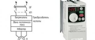
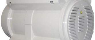
Three-phase asynchronous motors have found the widest application in industry and other fields. Modern equipment is simply impossible to imagine without these units. One of the most important components of the operating cycle of machines and mechanisms is their smooth start and the same smooth stop after completing the task. This mode is provided by using frequency converters. These devices have proven to be most effective in large, high-power electric motors.
With the help of frequency converters, inrush currents can be successfully adjusted, with the ability to control and limit their magnitude to the required values. To use this equipment correctly, you need to know the operating principle of a frequency converter for an asynchronous motor. Its use can significantly increase the service life of equipment and reduce energy losses. Electronic control, in addition to soft start, provides smooth adjustment of the drive in accordance with the established relationship between frequency and voltage.
What is a frequency converter
The main function of frequency converters is to smoothly regulate the rotation speed of asynchronous motors. For this purpose, a three-phase voltage with variable frequency is created at the output of the device.
Frequency converters are often called inverters. Their basic principle of operation is to rectify the alternating voltage of an industrial network. For this purpose, rectifier diodes are used, combined into a common unit. Current filtering is carried out by high-capacitance capacitors, which reduce the ripple of the incoming voltage to a minimum. This is the answer to the question why a frequency converter is needed.
In some cases, the circuit may include a so-called energy drain circuit, consisting of a transistor and a resistor with high power dissipation. This circuit is used in braking mode to suppress the voltage generated by the electric motor. This prevents capacitors from overcharging and premature failure. As a result of the use of frequency drives, asynchronous motors are successfully replacing DC electric drives, which have serious disadvantages. Despite the ease of adjustment, they are considered unreliable and expensive to operate. During operation, the brushes constantly spark, and electrical erosion leads to wear on the commutator. DC motors are completely unsuitable for explosive and dusty environments.
Safety precautions when connecting a frequency converter
There are several basic safety rules that need to be remembered when performing work on connecting frequency converters:
- It is strictly forbidden to touch live elements of the circuit with any part of the body. This can harm your health or even take your life. Before starting work, it is recommended to completely disconnect the equipment and use special electrical installation tools with protection against electric shock.
- It is worth remembering that even after the indicators on the device go out, voltage may remain in the circuit. To avoid electric shock when working with systems up to 7 kW, you must wait 5 minutes before starting work, with units over 7 kW - 15 minutes. This time should be enough for all capacitors in the circuit to discharge.
- Grounding is an integral part of any electrical circuit, including the frequency converter-motor circuit. It must be installed as a separate cable and under no circumstances can it be connected to the zero bus.
- It is worth remembering that turning off the frequency converter does not guarantee that there is no voltage left in other network nodes, so before repair or maintenance it is necessary to completely disconnect the circuit from the network.
Only qualified specialists with appropriate training and the necessary approvals can carry out work on connecting frequency converters.
Operating principle of the frequency converter
Efficient and high-quality control of asynchronous electric motors has become possible through the use of frequency converters together with them. The overall design is a variable frequency drive, which has significantly improved the technical characteristics of machines and mechanisms.
The control element of this system is a frequency converter, the main function of which is to change the frequency of the supply voltage. Its design is made in the form of a static electronic unit, and the generation of an alternating voltage with a given variable frequency is carried out at the output terminals. Thus, by changing the voltage amplitude and frequency, the rotation speed of the electric motor is adjusted.
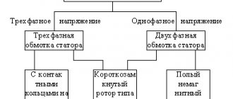
Asynchronous motors are controlled in two ways:
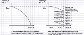
- Scalar control operates in accordance with a linear law, according to which amplitude and frequency are proportionally related to each other. The changing frequency leads to changes in the amplitude of the incoming voltage, affecting the torque level, efficiency and power factor of the unit. The dependence of the output frequency and supply voltage on the load torque on the motor shaft should be taken into account. In order for the load torque to be always uniform, the ratio of the voltage amplitude to the output frequency must be constant. This balance is precisely maintained by the frequency converter.
- Vector control keeps the load torque constant throughout the entire range of frequency adjustments. Control accuracy increases and the electric drive responds more flexibly to changing output loads. As a result, the motor torque is directly controlled by the converter. It must be taken into account that the torque is formed depending on the stator current, or more precisely, on the magnetic field it creates. Under vector control, the phase of the stator current changes. This phase is the current vector that directly controls the torque.
Menu
JSC "Automated Systems and Complexes" (ASK) has extensive experience in the design, manufacture and commissioning of non-standard equipment to solve problems in the field of reconstruction and modernization of electric drive systems in various industries. The setting of reconstruction tasks arises from the need to replace morally and physically obsolete electrical equipment in order to ensure maximum productivity of the technological process while minimizing capital and operating costs. As a rule, serial products from leading global manufacturers are offered as new equipment. However, in a number of cases, the use of such products is difficult due to the specific properties of the reconstruction object. The successful experience of the ASK enterprise with the products of one of the leaders in the field of manufacturing power semiconductor devices SEMIKRON, the existing scientific and technical potential allows us to solve such non-standard problems by manufacturing unique converter devices with non-standard solutions in the field of topology of the power part of the converters and control algorithms.
Currently, in metallurgical production, electric drives of transport roller tables of some mechanisms and technological sections operate in a mode where the frequency and effective value of the supply voltage differ from the standard one. In particular, a common option is to power the roller table sections with a linear voltage of 190 V at a frequency of 25 Hz. The rated load current is usually 1000-1500 A. The voltage source in this case in many enterprises is an electric machine frequency converter, which forms a three-phase voltage system with specified parameters. With high voltage quality indicators, such converters have two most significant drawbacks:
- large weight and dimensions;
- high degree of physical wear.
The use of standard frequency converters in this case is limited by the following factors:
- high current through the power capacitors of frequency converters due to the low load power factor (no more than 0.5);
- the use of existing cable lines to power the electric drive, which imposes strict requirements on the amplitude and rate of change of voltage at the output of the converter;
- possibility of long-term operation of frequency converters in idle mode when the load is disconnected.
Under these conditions, replacing an electric machine frequency converter with a serial static converter is possible by overestimating the power of the latter and using a sine wave filter at the output of the converter.
The results of the technical and economic analysis, carried out using a simulation modeling apparatus, showed that the most rational option for solving the reconstruction problem is to replace the electrical machine frequency converter with a non-standard semiconductor frequency converter with pulse width modulation (PWM) of the output voltage.
The schematic diagram of the developed frequency converter is shown in Fig. 1.
Rice. 1. Schematic diagram of the frequency converter
Main technical characteristics of the frequency converter.
- The rated current at the output of the converter is 1150 A. Current overload is no more than 10% for 60 s for a period of at least 10 min.
- Stable operation in steady state in the frequency range from 15 to 25 Hz.
- The maximum effective value of the first harmonic component of the linear voltage at the output of the frequency converter is 190 V.
- Static frequency reference error (average value) is not more than 0.1% of the maximum value of 25 Hz.
- Electric drive braking options: - standard, using frequency braking mode; — emergency, using dynamic braking mode.
- The frequency increase and decrease times during starting and braking are adjustable and can be selected from a range of 1 to 10 s. In this case, the braking rate can be automatically adjusted to ensure an accident-free stop.
- The voltage at the output of the frequency converter is formed as a function of frequency according to a law that ensures the operability of roller tables over the entire possible load range.
- PWM frequency: - with load 1 kHz; - at idle 0.25 kHz.
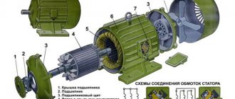
- The operating mode is 24 hours a day, with periodic scheduled stops for maintenance. Structurally, the frequency converter consists of a power transformer and three cabinets:
- input cabinet (power switching equipment, rectifier);
- autonomous inverter cabinet (capacitor battery, power transistor modules, control controller);
- cabinet of output reactors (specialized reactors for limiting the rate of change of voltage at the output of the frequency converter).
In Fig. Figure 2 shows the appearance of the autonomous inverter cabinet.
Rice. 2. Exterior view of a cabinet with an autonomous voltage inverter
To reduce the input voltage, a standard power transformer of the TSZ series is used. The use of reduced voltage, along with the use of specialized output reactors, made it possible to significantly reduce the absolute values of peak voltages and limit the rate of change in voltage across the load. The absolute value of peak overvoltages at the output of the reactors does not exceed 600 V, the rate of voltage change at the load is no more than 150 V/μs. This is illustrated by the oscillogram of the linear voltage at the load shown in Fig. 3.
Rice. 3. Voltage oscillogram at the reactor output
SKKD 700 modules are used as power semiconductor elements in the rectifiers, and SKiiP 2403 GB 122-4DUL modules are used in the autonomous inverter, which are arranged horizontally to reduce the dimensions of the cabinet. The total capacity of the capacitor bank is 30,000 µF, power
the capacitors are distributed over three sections, their electrical terminals are connected to copper plates (the use of the latter is due to the need to reduce the parasitic inductance of the lines).
To control asynchronous electric motors of roller tables, a modified version of scalar control is used. In particular, algorithms were used to minimize the stator current and combined premodulation, which makes it possible to make maximum use of the autonomous inverter in terms of voltage and improve the shape of the current at the output of the frequency converter. By using the algorithm for minimizing the stator current, it was possible to significantly limit the currents when starting the electric drives of the roller table section, and through the use of combined premodulation, it was possible to ensure the value of the current distortion coefficient within 10-15%. Oscillograms of the starting and steady-state load currents are shown in Fig. 4 and 5.
Rice. 4. Oscillogram of the starting load current. The effective value of the steady current is 125 D
Rice. 5. Oscillogram of steady-state load current. Effective current value - 125 D
To control the frequency converter, a specialized controller was used, developed and manufactured by ASK based on the TMS320 series DSP processor.
The operating experience of frequency converters confirmed the correctness of the decisions made and showed the effectiveness of replacing electric machine frequency converters with modern semiconductor ones when using existing cables and electric drives.
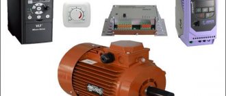
Setting up a frequency converter for an electric motor
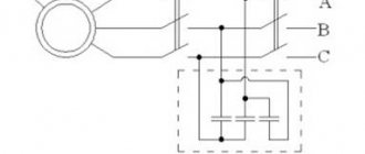
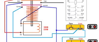
In order for the frequency converter for an asynchronous motor to fully perform its functions, it must be correctly connected and configured. At the very beginning of the network connection, a circuit breaker is placed in front of the device. Its rating must match the amount of current consumed by the motor. If the frequency generator is intended to be operated in a three-phase network, then the machine must also be three-phase, with a common lever. In this case, if there is a short circuit in one of the phases, you can quickly turn off the other phases.
The actuation current must have characteristics that fully correspond to the current of an individual phase of the electric motor. If the frequency converter is planned to be used in a single-phase network, in this case it is recommended to use a single circuit breaker, the rating of which should be three times the current of one phase. Regardless of the number of phases, when installing a frequency switch, the machines should not be connected to a break in the ground or neutral wire. It is recommended to use direct connection only.
If the frequency converter is correctly configured and connected, its phase wires must be connected to the corresponding contacts of the electric motor. The pre-windings in the motor are connected in a star or delta configuration, depending on the voltage supplied by the converter. If it matches the smaller value indicated on the motor housing, then a delta connection is used. At higher values, a star circuit is used.
Next, the frequency converter is connected to the controller and control panel, which is included in the delivery package. All connections are made in accordance with the diagram given in the instruction manual. The handle must be in the neutral position, after which the machine turns on. Normal activation is confirmed by an indicator light on the remote control. In order for the converter to work, the RUN button, programmed by default, is pressed.
Disadvantages of frequency converters
Frequency converters also have their disadvantages. These include:
- Expensive. Frequency converters are the most expensive conversion equipment. True, this disadvantage is very relative, taking into account the fact that such devices make it possible to extend the life of electric motors, as well as increase the period of their maintenance-free operation.
- Limitation. Not all old electric motors are capable of working in conjunction with a frequency converter. Even if this is possible from a technical point of view, the operational life of outdated models may simply not be enough for constant jumps in frequency and shaft rotation speed.
- Difficulty setting up and connecting. The frequency converter is quite difficult to install on your own, so to perform such work you often have to involve third-party specialists, and this in turn entails certain financial costs.
If we compare the disadvantages and advantages of frequency converters, they still look more efficient even compared to other converter devices. This is what makes them especially popular in manufacturing industries, where they are used almost everywhere.
Third
Almost every frequency converter is supplied with a remote control panel. Despite the fact that the frequency transmitter itself already has an interface for entering control and programming data, the presence of a remote control panel is a very convenient option.
The remote control is mounted in the place where it is most convenient to work with it. In some cases, when the frequency converter is somewhat inferior in dust and moisture protection, the frequency converter itself can be installed away from the engine, and the control panel nearby, so as not to run to the control cabinet and adjust the speed there.
It all depends on the specific circumstances and production requirements.
First start-up and configuration of the frequency converter
After connecting the control panel to the frequency converter, the motor shaft rotation speed handle should be moved to the lowest position. After this, you need to turn on the machine, thereby supplying power to the frequency converter. As a rule, after turning on the power, the light indicators on the frequency converter should light up and, if there is an LED panel, the starting values should be displayed on it.
The principle of connecting control circuits of a frequency converter is not universal. It is necessary to follow the instructions specified in the instructions for a specific frequency device.
To start the engine for the first time, you will need to briefly press the start button on the frequency converter. Typically, this button is programmed to start the engine by default at the factory.
After starting, the motor shaft should begin to rotate slowly. It is possible that the engine will rotate in the opposite direction, which is different. From the necessary. The problem can be solved by programming the frequency switch to reverse the movement of the shaft. All modern frequency converter models support this function. You can also use a primitive connection of phases in a different phase order. Although this takes a long time and is not cost-effective in terms of the time and effort of an electrician.
Further adjustment involves setting the desired engine speed. Often, the frequency display does not display the speed of the motor shaft, but the frequency of the voltage supplying the motor, expressed in hertz. Then you will need to use the table to determine the corresponding voltage frequency value to the engine shaft rotation speed.
When installing and servicing, as well as replacing the frequency converter, it is important to follow a number of recommendations.
- Any contact with a hand or other part of the body of a current-carrying element can take away health or life. This is important to remember when doing any work on the control cabinet. When working with the control cabinet, you should turn off the incoming power and make sure that the phases are turned off.
- It is important to remember that some voltage may still remain in the circuit even if the indicator lights go off. Therefore, when working with units up to 7 kW, after turning off the power, it is recommended to wait at least five minutes. And when working with devices over 7 kW, you need to wait at least 15 minutes after turning off the phases. This will allow all capacitors in the circuit to discharge.
- Each frequency converter must have reliable grounding. Grounding is checked according to the rules of preventive maintenance.
- It is strictly prohibited to use a neutral cable as grounding. Grounding is mounted with a separate cable separately from the zero bus. Even if there is a zero bus and a ground bus, if they comply with electrical installation standards, it is prohibited to connect them.
- It is important to remember that the frequency switch off key does not guarantee that the circuits will be de-energized. This key only stops the engine, while a number of circuits may remain energized.
The frequency converter is connected to the electric motor using cables whose cross-section corresponds to the characteristics specified in the frequency converter’s passport. Violation of norms to a lesser extent is unacceptable. On the larger side, it may not be advisable.
Recommendations for purchasing frequency converters
Buying a frequency converter is quite a responsible matter, because such devices are quite expensive and very serious tasks are assigned to them, so incorrect operation of the equipment can lead not only to financial losses, but also to the stoppage of entire production or other work.
Before buying a frequency converter, you must:
- Decide on the parameters that will match your electric motor.
- Draw up a working diagram according to which the equipment will be installed and connected.
- Select additional models that will be connected to the converter itself.
- Purchase all necessary cables, fastenings and frames required for installation.
- Prepare the work site for installation. It may be necessary to install additional power supplies or reorganize production equipment to be able to connect to the converter.
Many people buy used devices due to the high cost of frequency converters. This approach is riskier than buying new products, but it can save you some money. If you also decide to buy a used converter, then you should carefully check it not only for external signs, but also in operation. It is best if the seller does not dismantle it from his facility and is able to demonstrate its performance in practice.
Again, if you have never encountered the purchase of a frequency converter, it is better to entrust this matter to a professional who can select the appropriate model for you and help with its installation.
How the device works
Let us next consider the principle of operation of the frequency converter under consideration.
A frequency converter with pulse-width control first equalizes the mains voltage using a diode bridge, and then it is smoothed and filtered by capacitors. And this is the first stage of transformation.
At the next step, using microcircuits and output bridge IGBT switches, a sequence of a specific duty cycle and frequency is formed from the DC voltage. Rectangular pulses are generated at the output of the frequency converter, but due to the inductance of the windings, they are integrated and converted into a voltage close to a sinusoid.
How to choose an HRO?
- by function. Most budget converters have only the most important functions, but there is competition among manufacturers, and therefore basic variations in their functionality can differ significantly.
- according to the control method. There are two options here: scalar and vector control. Vector is more modern, widespread and complex. Scalar is suitable for simple devices, and is cheaper.
- by power. If the power of the equipment is approximately equal, then you should choose converters from the same company based on the maximum load indicator.
- according to mains voltage. It is recommended to select a converter with the largest range of upper and lower values.
- according to the frequency adjustment range. Depending on the operating frequencies of the drive and focusing on the maximum permissible values, you should select a converter with a suitable frequency range.
Emergency stop of the inverter
In addition to a regular stop, the Stop function with a specified deceleration uses two methods of emergency stopping the engine and turning off the inverter.
- Emergency stop by power interruption. To do this, manufacturers recommend installing a three-phase linear contactor before powering the inverter, the power supply of the coil depends on the state of the emergency circuit of all equipment. When you press the “Emergency Stop” button or in another emergency, the power to the contactor is turned off and the voltage from the inverter is removed. This will ensure that the engine stops.
- The function of discrete input DI1…DI6 “External device fault alarm” is used. If you program the desired input for this function, the inverter will stop if an alarm occurs.
Other useful materials:
Subtleties of setting up a frequency converter FAQ on electric motors Setting up a frequency converter to operate on multiple motors Purpose and types of encoders
Additional features and options
A modern frequency converter for an electric motor is a complex device. If it is processor-based, then it has many functions. Even inexpensive models can have wide functionality. To make a justified choice, you should know what each of the parameters means and why this or that function is needed.
- Output frequency or range of its variation. Everything is clear here. This parameter describes the possibilities for changing the output frequency.
- Voltage regulation limits. There are no questions either.
- Frequency conversion type. Can be vector or scalar. Scalar is used in simpler models. The parameters are monitored by the relationship between voltage and frequency. The vector type of frequency conversion to FM adjusts the work so that, relative to the load, the torque is constant. This control method is more complex and reliable, and is used in more expensive models.
- Availability of PID controller. Maintains pressure, temperature and speed within specified limits (set using a knob or programmed). To communicate with other controls, it must have signal outputs (analog and/or digital).
- Speed adjustment. Helps stabilize engine operation during power changes or surges.
List of characteristics of frequency converter SV015IG5A-4
- Type of braking. It is usually recommended to stop the motor on a free run - turn off the power and wait until it stops. Smooth braking can be used - a gradual decrease in voltage. Mechanical braking - when the speed of rotation of the shaft is slowed down due to friction. The rotor stops fastest during dynamic braking. In this case, a constant voltage is applied to one of the phases. It interacts with the rotor, stopping it in a short period of time.
- Number of outputs with different frequencies. Such a frequency converter for an electric motor can serve several engines at once with different (fixed) rotation speeds.
In addition to parameters and additional features, the performance is affected by the build quality. Naturally, it is better to take equipment from well-known manufacturers. ABB, Siemens, Mitsubishi, Omron have proven themselves well. But their frequencies cannot be called cheap. If you need to save money and appearance is not so important, pay attention to domestic and Belarusian manufacturers. The external design, as usual, wants to be better, but the characteristics and stability of operation are not bad.
Field of application of EKF frequency converters
Frequency converters have found wide application in all industrial areas. This device allows you to effectively control industrial equipment. Also, frequency drives are used as drives for various types of control valves, in pumping equipment, etc. It would be the right decision to purchase EKF frequency converters, the price of which is significantly lower than analogues from other companies.
For what purposes is it best to use EKF frequency converters?
Frequency generators are used to save energy and increase the service life of asynchronous electric motors. It is better to choose EKF frequency converters whose price will be much more affordable than the cost of other analogues. These converters are also widely used in everyday life. Frequency converters today can be found, say, in autonomous heating boilers, where the speed of the circulation pump is regulated using a frequency converter. Using a converter not only saves energy, but also distributes the coolant more efficiently throughout the heating circuit.
Source
Features of operating motors with frequency converters
As mentioned above, using a frequency converter for an electric motor, we reduce power losses by reducing the reactive component of the current. In addition, there are some points you need to know:
- When operating at reduced speed, the engine may overheat. This occurs by reducing the speed of natural airflow. Overheating is especially noticeable at speeds close to nominal. To reduce the temperature in this case, it is advisable to use additional airflow.
- When operating a standard electric motor (at 50 Hz) at increased rotation speeds, it is worth considering the condition of the bearings. Due to the stronger vibration that occurs, they fail faster. To level out this phenomenon, vibration damping pads can be used. In addition, the frequency must be chosen so that resonance does not occur. And keep in mind: at higher speeds the electric motor fan will make more noise.
It is necessary to take into account the specifics of the work
- When the shaft rotation speed decreases, for normal operation it is necessary to proportionally reduce the load. An asynchronous motor provides maximum torque only at rated speed. Therefore, as the frequency decreases, it falls.
- For long-term operation at reduced speeds, electric motors with a reduced rated frequency are used - from 750 rpm to 1500 rpm. The second option is engines with increased power.
- If you choose a frequency converter for a submersible pump, you need to make a choice not only by power, but also by current. Motors for this category of pumps have a significantly higher rated current. With a large cable length from the inverter to the pump, the voltage can drop significantly, which leads to a decrease in the rotation speed of the electric motor shaft. To make the drop less significant, use a cable with an oversized conductor cross-section.
A frequency converter for an electric motor expands the possibilities of its use. This is important, but it is equally important to choose it correctly, taking into account all the features of the job. This guarantees long-term operation of both devices.