Asynchronous motor controller
Hello everybody.
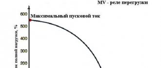
On the Internet, and in general, the question often arises: how to control the fan speed for an asynchronous motor? It is known that we can easily control the speed of a motor using a phase controlled triac. And also, the literature contains information that an asynchronous motor rotates at a speed from a few percent to 20% lower than the synchronous speed. Therefore, the answer to the question of regulating the rotation of an asynchronous motor is an inverter. However, this device is quite expensive, and the point of doing it on your own is debatable. It is also believed that using a phase power regulator using a triac for this purpose is not possible. However, this belief is not entirely true. For some motors and loads, the use of a phase-controlled triac allows speed control over a wide range.
Integrated circuits are available in such simple phase regulators. By taking into account the limitations imposed by the phase controller system, we can very easily create a normally operating speed controller for an induction motor. Let's try to consider what happens after connecting an asynchronous motor to a typical dimer, which is usually made in accordance with the diagram shown in the figure.
Let's consider the case (graphic drawing) when the triac is turned on at an angle = 100 after the mains voltage passes through zero. The conduction angle will be about 150 degrees, so the triac will turn off at an angle of about 250 degrees at point B. A residual positive voltage will remain on capacitor C1 since it is not fully discharged through the triac.
At this moment, a negative voltage appears in the triggering system, which first charges the residual voltage to C1, and then triggers the triode at an angle of about 350. The second turn on of the triac will occur at a very low voltage, and the conduction angle will be much smaller than the first. In the next period, the conditions are similar, so a significant asymmetry in the activation of the triac in the negative and positive half-cycles remains. Such asymmetry is unacceptable in the motor control circuit; it can even be dangerous due to saturation of the magnetic system.
Four standard diodes, two resistors and a potentiometer have been added to the standard dimer circuit shown in the figure.
In the first half-cycle, the system behaves in the same way as the circuit from the previous figure. However, after the appearance of a negative voltage, the residual positive voltage on C1 is discharged through diode D4 and resistor R2. Diode D3 prevents further charging with the negative voltage of C1, even after the positive voltage has been discharged. Elements D1, D2 and R1 perform a similar function in the positive half-cycle. As a result of the operation of the symmetrization scheme, after several periods the asymmetry is eliminated.
Elements R5 and C2 smooth out voltage surges that occur after the triac is turned off at point B. Without them, a rapid increase in the output voltage can lead to the triac turning on. Resistor R4 increases the trigger pulse time. Without it, this time will be determined by the capacitance C1 and the internal resistances of the elements C1, T1 and T2 and will be too short to properly start the triac.
The current across the inductive load increases slowly after the triac is turned on; if the pulse is too short, it may not reach the IL value of the “latching” current, and the triac will turn off after the gate pulse. IL for typical triacs ranges from several to several tens of milliamps.
The circuit can be assembled on a printed circuit board shown in the figure in the text.
It is worth paying attention to the fact that during operation the full mains voltage is present. So don't go overboard with miniaturizing your device. It is possible that the regulator will operate in conditions of high humidity and, possibly, even chemically aggressive ones. Therefore, the distance between the tracks must be a considerable distance, which entails the size of the board.
Difficulties in PWM speed control of a DC motor
PWM is a popular method for regulating analog voltage in various circuits. When using this control method, the user may experience unpredictable motor behavior. For example, the shaft may begin to rotate in the opposite direction. This occurs at low capacitive loads. In commutator motors, the armature windings are constantly switched during operation. When the regulator is connected, the power switches off and on at a certain frequency. Additional commutation in combination with a commutator can lead to problems with engine operation. Therefore, control devices with PWM motor control must be carefully thought out and designed.
Also, the cause of unstable operation of the electric motor may be the fact that the current strength influences the rotor rotation speed, which depends on the level of applied voltage. Problems may arise when operating motors at low speed relative to the rated speed.
For example, the user has a motor that, at rated voltage, rotates the rotor at a speed of 10 rpm. To reduce the speed to 1 rps, it is not enough to simply reduce the voltage to 1V. It is difficult to select the appropriate value of the supplied voltage, and even if the user succeeds, with a slight change in operating conditions, the speed will change again.
The solution to the problem is to use an automatic control system or briefly turn on the electric motor at full power. The rotor will move jerkily, but with the correct frequency and duration of the applied pulses, the rotation can be made more stable. Thus, they achieve stable movement of the electric motor shaft at any speed that will not change depending on the load.
The simplest DIY electric motor speed controller
When making various homemade products, you have to face a number of problems and find solutions for them. This is the case with various devices that have a commutator electric motor in their design.
Very often it is necessary to make the engine have adjustable speed. For these purposes, an engine speed regulator (controller) is used, which you can assemble yourself.
The regulator presented below for electric motors allows not only to ensure a smooth start of the motor and the degree of speed control, but also to protect the motor from overloads. The controller can operate not only from 220 Volts, but also from reduced voltage, up to 110 Volts.
Characteristics of a homemade controller
- Voltage range (110-240 Volts);
- Possibility of adjusting the electric motor speed, from 9-99%;
- Load, up to 2.5 kW;
- Operating power: no more than 300 W.
A homemade speed controller for an electric motor has a low noise level, it allows for smooth stabilization of speed and soft starting of the electric motor.
Below is a diagram of a speed controller for an electric motor and the principle of its operation.
Speed controller circuit for an electric motor
To assemble a speed controller for an engine, you will need a PWM pulse generator and a triac to control the engine. The diode and resistor D1 and R1 allow you to reduce the voltage to power the motor, and the capacitor C1 is designed to filter the current at the input of the electrical circuit.
Elements P1, R5 and R3 are voltage dividers with the ability to adjust its values. Resistor R2, which is indicated on the diagram of the electric motor speed regulator, allows you to synchronize the internal blocks of the regulator with the main triac (VT139), on which the speed regulator actually operates.
Below in the figure you can see a visual arrangement of all elements of the speed controller for electric motors. It is imperative to place the elements safely, since the regulator operates from a dangerous voltage of 220 Volts.
DC brushed motor control circuit
A simple DC motor control circuit can be assembled from a field effect transistor. It plays the role of an electronic key that switches the motor power circuit after voltage is applied to the base. The electronic key remains open for a time corresponding to the pulse duration.
The PWM signal is characterized by a duty cycle, which is equal to the inverse of the duty cycle. The duty cycle is equal to the ratio of the pulse duration to the period of its supply
The speed of the motor shaft will be proportional to the duty cycle value. Therefore, if the frequency of the PWM signal is too low to ensure stable operation, the motor shaft will rotate noticeably jerkily. To guarantee smooth regulation and stable operation, the frequency must exceed hundreds of hertz.
Speed controller power and load
A load of no more than 2 kW can be connected to a homemade engine speed controller, made according to the above diagram. If the load increases, the main triac BT138/800 is replaced. If a triac is installed with a higher rating, then it is recommended to move it outside the common board, and be sure to install it on a cooling radiator, which can be made from a piece of aluminum strip.
It is noteworthy that such a regulator can be used not only with electric motors, but also with lighting lamps. Thus, cheaply and cheerfully, you can assemble a regulator for the brightness of lighting lamps.
Subscribe to my Zen channel. Good luck to everyone, and peaceful skies above your heads!
Source
Rotation speed control of single-phase motors
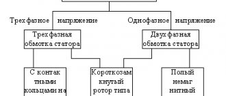
Single-phase asynchronous motors are powered from a conventional 220 V alternating voltage network.
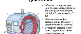
The most common design of such motors contains two (or more) windings - working and phase-shifting. The working one is fed directly, and the additional one is fed through a capacitor, which shifts the phase by 90 degrees, which creates a rotating magnetic field. Therefore, such motors are also called two-phase or capacitor motors.
It is necessary to regulate the rotation speed of such motors, for example, for:
- changes in air flow in the ventilation system
- pump performance control
- changes in the speed of moving parts, for example in machine tools, conveyors
Features of speed control
It is important to know that each motor, when rotating, consumes not only active, but also reactive power. In this case, the reactive power level will be higher, which is due to the nature of the load
In this case, the task of designing devices for regulating the rotation speed of commutator motors is to reduce the difference between active and reactive powers. Therefore, such converters will be quite complex, and it is not easy to make them yourself.
You can construct only some semblance of a regulator with your own hands, but there is no point in talking about saving power. What is power? In electrical terms, it is the current drawn multiplied by the voltage. The result will give a certain value that includes active and reactive components. To isolate only the active one, that is, to reduce losses to zero, it is necessary to change the nature of the load to active. Only semiconductor resistors have these characteristics.
Therefore, it is necessary to replace the inductance with a resistor, but this is impossible, because the motor will turn into something else and obviously will not set anything in motion. The goal of lossless regulation is to maintain torque, not power: it will still change. Only a converter can cope with such a task, which will control the speed by changing the duration of the opening pulse of thyristors or power transistors.
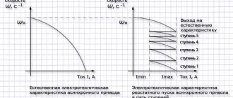
Voltage regulation
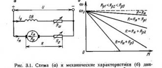
Speed control in this way is associated with a change in the so-called engine slip - the difference between the rotation speed of the magnetic field created by the stationary engine stator and its moving rotor:
n1— magnetic field rotation speed
n2 — rotor rotation speed
In this case, sliding energy is necessarily released - which causes the motor windings to heat up more.
This method has a small control range, approximately 2:1, and can also only be carried out downwards - that is, by reducing the supply voltage.
When regulating speed in this way, it is necessary to install oversized motors.
But despite this, this method is used quite often for low-power motors with a fan load.
In practice, various regulator circuits are used for this.
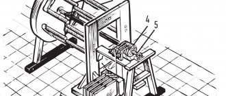
Autotransformer voltage regulation
An autotransformer is an ordinary transformer, but with one winding and taps from some of the turns. In this case, there is no galvanic isolation from the network, but in this case it is not needed, so savings are achieved due to the absence of a secondary winding.
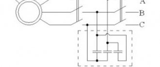
The diagram shows autotransformer T1 , switch SW1 , which receives taps with different voltages, and motor M1.
The adjustment is done in steps; usually no more than 5 steps of regulation are used.
Advantages of this scheme:
- undistorted output voltage waveform (pure sine wave)
- good overload capacity of the transformer
Flaws:
- large mass and dimensions of the transformer (depending on the power of the load motor)
- all the disadvantages inherent in voltage regulation
Thyristor engine speed controller
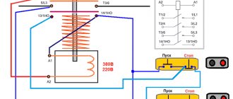
This circuit uses keys - two thyristors connected back-to-back (the voltage is alternating, so each thyristor passes its own half-wave of voltage) or a triac.
The control circuit regulates the moment of opening and closing of the thyristors relative to the phase transition through zero; accordingly, a piece is “cut off” at the beginning or, less often, at the end of the voltage wave.
This changes the rms voltage value.
This circuit is quite widely used to regulate active loads - incandescent lamps and all kinds of heating devices (so-called dimmers).
Another method of regulation is to skip half-cycles of the voltage wave, but at a network frequency of 50 Hz this will be noticeable for the motor - noise and jerking during operation.
To control motors, regulators are modified due to the characteristics of the inductive load:
- install protective LRC circuits to protect the power switch (capacitors, resistors, chokes)
- add a capacitor at the output to adjust the voltage waveform
- limit the minimum voltage regulation power - for guaranteed engine start
- use thyristors with a current several times higher than the electric motor current
Advantages of thyristor regulators:
Flaws:
- can be used for low power engines
- During operation, noise, crackling, and jerking of the engine may occur.
- when using triacs, a constant voltage is applied to the motor
- all the disadvantages of voltage regulation
It is worth noting that in most modern mid- and high-level air conditioners, the fan speed is adjusted in this way.
Transistor voltage regulator
As the manufacturer himself calls it, an electronic autotransformer or PWM regulator.
The voltage is changed using the PWM (pulse width modulation) principle, and transistors are used in the output stage - field-effect or bipolar with insulated gate (IGBT).
The output transistors are switched at a high frequency (about 50 kHz); if you change the width of the pulses and pauses between them, the resulting voltage at the load will also change. The shorter the pulse and the longer the pause between them, the lower the resulting voltage and power input.
For a motor, at a frequency of several tens of kHz, a change in the pulse width is equivalent to a change in voltage.
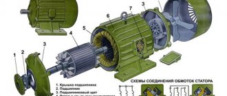
Motor design
Structurally, the engine from the Indesit washing machine is simple, but when designing a controller to control its speed, it is necessary to take into account the parameters. Motors may have different characteristics, which is why the control will also change. The operating mode is also taken into account, which will determine the design of the converter. Structurally, the commutator motor consists of the following components:
- An armature, it has a winding laid in the grooves of the core.
- Collector, a mechanical rectifier of alternating mains voltage, through which it is transmitted to the winding.
- Stator with field winding. It is necessary to create a constant magnetic field in which the armature will rotate.
When the current in the motor circuit, connected according to the standard circuit, increases, the field winding is connected in series with the armature. With this inclusion, we also increase the magnetic field acting on the armature, which allows us to achieve linearity of characteristics. If the field remains unchanged, then it will be more difficult to obtain good dynamics, not to mention large power losses. It is better to use such motors at low speeds, since they are more convenient to control at small discrete movements.
By organizing separate control of the excitation and armature, it is possible to achieve high positioning accuracy of the motor shaft, but the control circuit will then become significantly more complicated. Therefore, we will take a closer look at the controller, which allows you to change the rotation speed from 0 to the maximum value, but without positioning. This may be useful if a full-fledged drilling machine with the ability to cut threads is made from a washing machine engine.
Frequency regulation
Just recently (10 years ago), there were a limited number of frequency controllers for motor speeds on the market, and they were quite expensive. The reason was that there were no cheap high-voltage power transistors and modules.
But developments in the field of solid-state electronics have made it possible to bring power IGBT modules to the market. As a consequence, there is a massive appearance on the market of inverter air conditioners, welding inverters, and frequency converters.
At the moment, frequency conversion is the main way to regulate the power, performance, speed of all devices and mechanisms driven by an electric motor.
However, frequency converters are designed to control three-phase electric motors.
Single-phase motors can be controlled by:
- specialized single-phase inverters
- three-phase inverters with the exception of the capacitor
Converters for single-phase motors
Currently, only one manufacturer announces serial production of a specialized inverter for capacitor motors - INVERTEK DRIVES.
Optidrive E2 model
For stable engine starting and operation, special algorithms are used.
In this case, frequency adjustment is possible upward, but in a limited frequency range, this is prevented by a capacitor installed in the phase-shifting winding circuit, since its resistance directly depends on the frequency of the current:
f - current frequency
C - capacitance of the capacitor
The output stage uses a bridge circuit with four output IGBT transistors:
Optidrive E2 allows you to control the motor without removing the capacitor from the circuit, that is, without changing the motor design - in some models this is quite difficult to do.
Advantages of a specialized frequency converter:
- intelligent motor control
- Stably stable engine operation
- the enormous capabilities of modern inverters: the ability to control the operation of the motor to maintain certain characteristics (water pressure, air flow, speed under changing load)
- numerous protections (motor and device itself)
- sensor inputs (digital and analogue)
- various outputs
- communication interface (for control, monitoring)
- preset speeds
- PID controller
Disadvantages of using a single-phase inverter:
Frequency controller structure
Most frequency converters for electric motors up to 690 V are designed according to the scheme of two-level voltage inverters. They allow you to simulate the supply voltage of the required shape and frequency amplitude. Such devices consist of an uncontrolled rectifier, 2 transistor switches per phase and a capacitor. The output voltage contains higher harmonics, which are smoothed out by the inductive load. Special filters are used relatively rarely.
The disadvantage of such a circuit is the limitation of the output voltage, which is determined by the maximum voltage of the semiconductor devices.
For high-voltage drives, multi-level control schemes are used. They consist of several single-phase inverters connected in series. This circuit avoids resonances, provides high performance, and reduces the rate of voltage rise. Such inverters have a modular design. If one of the cells fails, it is easy to replace. The disadvantages of this scheme include the need for a separate power source for each module, the functions of which are performed by a special-purpose transformer.
Frequency converters with floating capacitors make it possible to do without an input transformer and increase the number of cells depending on the required power. This solution ensures a reduction in higher harmonics and reduces the rate of voltage rise.
To regulate the speed of electric motors with intermittent operation and frequent reverses, current inverters are used. These devices are a controlled rectifier and an inverter using thyristors. To reduce noise in the load circuit, a split inductive filter is included in the circuit. The output voltage of such devices has the form of an approximate sinusoid. To smooth its shape, it is necessary to include capacitors in front of the electric motor. The main advantage of such inverters is the ability to recover electricity back into the power grid.
Direct frequency converters do not contain capacitors. Their main advantage is their small size and significant load power. Such devices are used as part of powerful electric drives operating at low speeds. Inverters of this type are made on the basis of thyristor converters. A phase-shifting transformer is installed at the input of direct inverters, eliminating lower harmonics and acting as a power source for each converter. Direct inverters require a complex control circuit.