Asynchronous motor - operating principle and device
On March 8, 1889, the greatest Russian scientist and engineer Mikhail Osipovich Dolivo-Dobrovolsky invented a three-phase asynchronous motor with a squirrel-cage rotor .
Modern three-phase asynchronous motors are converters of electrical energy into mechanical energy. Due to their simplicity, low cost and high reliability, asynchronous motors are widely used.
They are present everywhere, this is the most common type of engine, they are produced in 90% of the total number of engines in the world. The asynchronous electric motor truly made a technical revolution in the entire world industry.
note
The enormous popularity of asynchronous motors is associated with their ease of operation, low cost and reliability.
An induction motor is an asynchronous machine designed to convert alternating current electrical energy into mechanical energy. The word “asynchronous” itself means not simultaneous.
This means that in asynchronous motors the rotation frequency of the stator magnetic field is always greater than the rotor rotation speed. Asynchronous motors, as is clear from the definition, operate from an alternating current network.
Device
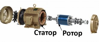
In the figure: 1 - shaft, 2.6 - bearings, 3.8 - bearing shields, 4 - paws, 5 - fan casing, 7 - fan impeller, 9 - squirrel cage rotor, 10 - stator, 11 - terminal box.
The main parts of an asynchronous motor are the stator (10) and the rotor (9).
The stator has a cylindrical shape and is assembled from steel sheets. The stator windings, which are made of winding wire, are laid in the grooves of the stator core. The axes of the windings are shifted in space relative to each other by an angle of 120°. Depending on the applied voltage, the ends of the windings are connected in a triangle or star.
rotors : squirrel cage and wound rotor.
The squirrel-cage rotor is a core made of steel sheets.
Molten aluminum is poured into the grooves of this core, resulting in the formation of rods that are short-circuited by end rings. This design is called a “ squirrel cage ”.
In high-power engines, copper can be used instead of aluminum. The squirrel cage is a short-circuited rotor winding, hence the name.
The phase rotor has a three-phase winding, which is practically no different from the stator winding. In most cases, the ends of the wound rotor windings are connected in a star, and the free ends are connected to slip rings.
Using brushes that are connected to the rings, an additional resistor can be introduced into the rotor winding circuit. This is necessary so that the active resistance in the rotor circuit can be changed, because this helps reduce large starting currents.
You can read more about the wound rotor in the article - asynchronous motor with a wound rotor.
Principle of operation
When voltage is applied to the stator winding, a magnetic flux is created in each phase, which changes with the frequency of the applied voltage. These magnetic fluxes are shifted relative to each other by 120°, both in time and in space. The resulting magnetic flux turns out to be rotating.
The resulting magnetic flux of the stator rotates and thereby creates an EMF in the rotor conductors.
Since the rotor winding has a closed electrical circuit, a current arises in it, which in turn, interacting with the magnetic flux of the stator, creates a starting torque for the engine, which tends to turn the rotor in the direction of rotation of the stator magnetic field. When it reaches the value of the braking torque of the rotor and then exceeds it, the rotor begins to rotate. In this case, the so-called slip occurs.
Slip s is a value that shows how much the synchronous frequency n1 of the stator magnetic field is greater than the rotor speed n2, as a percentage.
Slip is an extremely important quantity.
Important
At the initial moment of time it is equal to unity, but as the rotor rotation speed n2 increases, the relative frequency difference n1-n2 becomes smaller, as a result of which the emf and current in the rotor conductors decrease, which entails a decrease in torque.
In idle mode, when the engine is running without load on the shaft, the slip is minimal, but with an increase in the static torque, it increases to the value scr - critical slip.
If the engine exceeds this value, a so-called engine stall may occur, which can subsequently lead to unstable operation. The slip values range from 0 to 1; for general purpose asynchronous motors it is in nominal mode – 1 – 8%.
As soon as there is an equilibrium between the electromagnetic torque causing rotation of the rotor and the braking torque created by the load on the motor shaft, the processes of changing values will stop.
It turns out that the principle of operation of an asynchronous motor is the interaction of the rotating magnetic field of the stator and the currents that are induced by this magnetic field in the rotor. Moreover, torque can only occur if there is a difference in the rotational frequencies of the magnetic fields.
Recommended reading: single-phase asynchronous motor.
1 1 1 1 1 1 1 1 1 1 4.74 (430 Votes)
Source: https://electroandi.ru/elektricheskie-mashiny/asdvig/asinkhronnyj-dvigatel-printsip-raboty-i-ustrojstvo.html
History of the electric motor
May 1834, Jacobi
The first rotating electric motor.
Jacobi, 1834 German and Russian physicist, academician of the Imperial St. Petersburg Academy of Sciences, Boris Semenovich (Moritz Hermann von) Jacobi, invented the world's first electric motor with direct rotation of the working shaft. The engine power was about 15 W, the rotor speed was 80-120 rpm. Before this invention, there were only devices with a reciprocating or swinging motion of the armature.
1836 - 1837, Davenport
By experimenting with magnets, American blacksmith and inventor, Thomas Davenport, created his first electric motor in July 1834. In December of the same year, he demonstrated his invention for the first time. In 1837, Davenport received the first patent (U.S. Patent No. 132) for an electric machine.
1839, Jacobi
Using an electric motor powered by 69 Grove galvanic cells and developing 1 horsepower, in 1839 Jacobi built a boat capable of moving with 14 passengers along the Neva against the current. This was the first practical use of an electric motor.
1837 - 1842, Davidson
Scottish inventor, Robert Davidson, has been developing the electric motor since 1837. He made several drives for lathe and vehicle models. Davidson invented the first electric locomotive.
1856, Siemens
German engineer, inventor, scientist, industrialist, founder of Siemens, Werner von Siemens invented an electric generator with a double T-shaped armature. He was the first to place windings in slots.
1861-1864, Maxwell
British physicist, mathematician and mechanic, James Clerk Maxwell, summarized the knowledge of electromagnetism into four fundamental equations. Together with the expression for the Lorentz force, Maxwell's equations form a complete system of equations of classical electrodynamics.
1871-1873, Gram
The Belgian inventor, Zenob Théophilus Gramm, eliminated the disadvantage of electrical machines with a Siemens double-T armature, which consisted of strong pulsations of the generated current and rapid overheating. Gramm proposed the design of a self-excited generator that had a ring armature.
1885, Ferraris
Italian physicist and engineer, Galileo Ferraris, invented the first two-phase asynchronous electric motor. However, Ferraris thought that such a motor could not have an efficiency higher than 50%, so he lost interest and did not continue to improve the induction motor. It is believed that Ferraris was the first to explain the phenomenon of a rotating magnetic field.
1887, Tesla
Serbian-American inventor Nikola Tesla, working independently of Ferraris, invented and patented a two-phase induction motor with salient stator poles (lumped windings). Tesla mistakenly believed that a two-phase current system was optimal from an economic point of view among all multiphase systems.
1889-1891, Dolivo-Dobrovolsky
Russian electrical engineer of Polish origin, Mikhail Osipovich Dolivo-Dobrovolsky, after reading Ferraris’ report on a rotating magnetic field, invented a rotor in the form of a “squirrel cage”. Further work in this direction led to the development of a three-phase alternating current system and a three-phase asynchronous electric motor, which has been widely used in industry and has remained virtually unchanged to this day.
The widespread introduction of electromechanical devices in Russia began after the October Revolution of 1917, when the electrification of the entire country became the basis of the technical policy of the new state. We can say that the 20th century was the century of the formation and widespread dissemination of electromechanics.
Choosing between two-phase and three-phase systems
Dolivo-Dobrovolsky rightly believed that increasing the number of phases in the motor improves the distribution of the magnetizing force around the circumference of the stator. The transition to a three-phase system from a two-phase one already gives a big gain in this regard. A further increase in the number of phases is impractical, as it leads to a significant increase in metal consumption for wires.
For Tesla, it seemed obvious that the smaller the number of phases, the fewer wires are required, and therefore the cheaper the power transmission device. At the same time, a two-phase transmission system required the use of four wires, which seemed undesirable in comparison with two-wire systems of direct or single-phase alternating current. Therefore, Tesla proposed using a three-wire line for a two-phase system, making one wire common. But this did not greatly reduce the amount of metal spent on the system, since the common wire had to be of a larger cross-section.
Thus, the three-phase current system proposed by Dolivo-Dobrovolsky was optimal for energy transmission. It almost immediately found wide application in industry and to this day is the main electrical energy transmission system throughout the world.
Operating principle and design of an asynchronous motor
An asynchronous (induction) motor is a mechanism that converts alternating current into mechanical power. By asynchronous we mean that the speed of movement of the stator magnetic force is higher than the same value of rotor revolutions.
In order to better understand what an asynchronous motor is and the operating principle of a three-phase asynchronous motor, where it is used and how it works, it is necessary to understand its components and details, and examine the technical characteristics. In addition, it will not be amiss to understand how force is converted during startup and where an asynchronous motor is used in practice.
In today's article we will try to answer the most interesting questions related to asynchronous motors, understand what the design of a single-phase asynchronous motor is, consider the principles of operation, as well as the pros and cons of this type of device.
A little history
The first such electric motor mechanism appeared back in 1888 and was introduced by the American engineer Nikola Tesla. However, his prototype device was not the most successful, since it was two-phase or multi-phase and the performance characteristics of the asynchronous motor did not satisfy consumers. Therefore, it was not widely used.
But thanks to the Russian scientist Mikhail Dolivo-Dobrovolsky, it was possible to breathe new life into the invention. It was he who took the lead in creating the world's first three-phase asynchronous motor.
This design improvement was revolutionary, since the operating principle of a three-phase asynchronous motor made it possible to use only three wires for operation, rather than four.
Advice
So there were no more obstacles left for the smooth launch of the device into mass production.
Today, due to their simplicity, these machines are widely used, and the mechanical characteristics of the asynchronous motor suit all drivers.
Every year, the share of asynchronous motors among all motors in the world is 90%.
Ease of use, the principle of operation of an asynchronous motor, easy starting, reliability and low cost, helped these motors spread throughout the world and literally make a technical revolution in industry.
The operating principle of a three-phase motor is based on power from three phases of alternating current in a standard network. To operate, it requires exactly this kind of electricity and that is why it is called three-phase.
Three-phase motor device
Any asynchronous motor, regardless of its power and size, consists of the same parts; the mechanical characteristics of an asynchronous motor are also the same. The main components are:
- stator (fixed part of the machine)
- rotor (rotating part)
In addition, the following parts can be found in modern three-phase motors:
- shaft
- bearings
- winding
- grounding
- housing (in which all parts are mounted)
As mentioned above, the basic elements of the engine are the stator (fixed part) and the rotor (moving part).
The stator is made in the form of a cylinder; this element is composed of many metal, shaped sheets. The interior is designed to accommodate the winding. The centers of the windings are located at an angle of 120 degrees, and the connection is made based on the available voltage and two possible options: three or five contacts.
First experiments with electromagnetic devices
Electromechanics is a relatively young branch of science and technology, by historical standards.
1800, Volta
Italian physicist, chemist and physiologist, Alessandro Volta, was the first in the world to create a chemical current source.
1820, Ørsted
The Danish scientist and physicist Hans Christian Oersted experimentally discovered the deflecting effect of current on a magnetic needle.
1821, Faraday
The British experimental physicist and chemist, Michael Faraday, published a treatise "On Some New Electromagnetic Motions and the Theory of Magnetism", where he described how to make a magnetized needle rotate continuously around one of the magnetic poles. This design was the first to realize the continuous conversion of electrical energy into mechanical energy. It is considered to be the first electric motor
in history.
1822, Ampere
The French physicist, André Marie Ampère, discovered the magnetic effect of a solenoid (coil with current), which led to the idea that a solenoid is equivalent to a permanent magnet. Among other things, Ampere proposed using an iron core placed inside a solenoid to enhance the magnetic field. In 1820 he discovered Ampere's law.
1822, Barlow
English physicist and mathematician, Peter Barlow, invented the Barlow wheel, essentially a unipolar electric motor.
1825, Arago
French physicist and astronomer, Dominique François Jean Arago, published an experiment showing that a rotating copper disk causes a magnetic needle suspended above it to rotate.
1825, Sturgeon
British physicist, electrical engineer and inventor, William Sturgeon, in 1825 made the first electromagnet, which was a bent rod of soft iron with a winding of thick copper wire.
1827, Jedlik
Hungarian physicist and electrical engineer, Anjos Istvan Jedlik, invented the world's first dynamo (direct current generator), but did not announce his invention until the late 1850s.
The first practically useful Jacobi electric motor
ALEXANDER MIKEROV, Doctor of Technical Sciences, Prof. department automatic control systems SPbGETU "LETI"
The previous article in this series [1] was devoted to the first laboratory experiments that demonstrated the ability of electric current to produce mechanical rotation or rolling. However, due to the mercury commutator and negligible power, such devices were unrealistic to use in drive motors. The first practically useful electric motor, which immediately found its application, was created by the outstanding electrical engineer B. S. Jacobi. This article discusses various engine designs, as well as other inventions of this scientist, who glorified Russian science.
Rice. 1. Boris Semenovich Jacobi (1801–1874)
Boris Semenovich Jacobi (Fig. 1), in his youth Moritz Hermann Jacobi, was born in Potsdam (Prussia) into the family of a successful Jewish banker [2, 3]. His older brother Carl (Carl Jacobi) became a famous mathematician, whose name is imprinted in such concepts as the Jacobian, the Jacobian matrix, etc.
Following the example of many of his contemporaries, Moritz accepted Protestantism with the name Boris and was subsequently called Boris Semenovich in Russia (after Simon's father). He received his education first at the University of Berlin, and then at the famous University of Göttingen, graduating with a diploma in architecture. Afterwards he taught with his brother Karl at the University of Königsberg, where he became interested in electrical engineering and tried to create an electrical analogue of a steam engine.
In 1834, he decisively rejected this idea, built a working “magnetic apparatus” of rotational motion and sent its description to the Paris Academy of Sciences, which, after a favorable review by Ampère and Becquerel, was published in the proceedings of the academy, and then in the general press.
Rice. 2. Jacobi electric motor
A working sample of this engine, stored in the Moscow Polytechnic Museum, is shown in Fig. 2, where 1 is a stator winding with eight axial poles of electromagnets (excitation), 2 is a rotor, 3 is a rotor winding also with eight poles (armature), 4 is a brush-collector unit (commutator), then called a “gyrotrope,” with four metal contact levers and commutator disks, 5 - shaft, 6 - galvanic battery. The engine developed a power of 15 W at a speed of 40 rpm [3–5].
Consider the operating principle of a four-pole motor, as shown in Fig. 3, where the four fixed poles (1) of the two stator electromagnets are magnetized N-S-N-S, the apoles (3) of the rotor electromagnets (2) are remagnetized using a commutator depending on the position of the rotor. In the position shown in the figure, the angular position of the rotor is ? = 45°, the opposite poles of the rotor and stator attract and the torque is directed counterclockwise. When turning the rotor to an angle? = 90° the currents and poles of the armature switch to opposite ones, which maintains the sign of the torque. Thus, the motor rotates counterclockwise.
Rice. 4. Jacobi engine diagram
This is a classic DC electric motor of series excitation with a brush-commutator unit of an end design, the diagram of which in its modern design looks like that shown in Fig. 4, where 1 is the excitation winding, and 2 is the armature with a brush-collector assembly. It is interesting to note that the brush-commutator assembly of the engine, which is essentially a rotor position sensor, implements the feedback principle like any automatic system.
Rice. 3. Operating principle of the Jacobi electric motor
Publications about the Jacobi engine had far-reaching consequences, 3]. He himself received a doctorate and was invited as a professor to the University of Dorpat, which was then part of the Russian Empire (now the city of Tartu in Estonia). Professor of this university, astronomer Vasily Yakovlevich Struve, together with the famous electrical engineer, academician Pavel Lvovich Schilling, drew the attention of the Russian government to the usefulness of such an engine for shipbuilding. Emperor Nicholas I ordered to invite Professor Jacobi to build an “electric ship”, for which 50,000 rubles were allocated. To assess the impressiveness of this sum, we can recall that, as follows from Gogol’s poem “Dead Souls,” the price of a serf in those days was 100 rubles.
Jacobi enthusiastically accepted the offer, moved to St. Petersburg in 1837, became a Russian citizen, and for the next thirty-seven years faithfully served Russian science and technology as part of the St. Petersburg Academy of Sciences.
Fig 5. Second Jacobi engine
To build the “electric ship”, a special “commission was established for the application of electromagnetic force to the movement of machines according to the method of Prof. Jacobi" headed by Admiral Ivan Fedorovich Kruzenshtern, which included leading Russian electrical engineers Emilius Khristianovich Lenz and Pavel Lvovich Schilling [6]. An 8 m long boat was allocated, which required a much larger electric motor. Therefore, Jacobi creates a second version of his engine - larger in size and with a dual stator, providing an increase in magnetic flux (Fig. 5).
However, the power of this 120 W option was clearly insufficient, and Jacobi changed the entire concept of the engine, moving to a more compact design with all the electromagnets placed in the center plane, shown in Fig. 6, where 1 — two stator electromagnets, 2 — four rotor electromagnets, 3 — commutator [4, 5]. The principle of operation of the engine is exactly the same as in Fig. 3. The diametric design of the electric motor was proposed by the American inventor Thomas Davenport, who will be discussed in the next article.
Rice. 6. Third Jacobi engine
So, Jacobi assembles forty of these engines on two vertical parallel shafts connected by bevel gears to the paddle wheels of the “electric ship.” In 1838, its months-long testing began with up to 14 passengers riding along the Neva at a speed of 3 versts per hour, as shown in Fig. 7. The engines were powered by 320 advanced galvanic zinc-platinum elements weighing 200 kg, due to which the propeller drive power was increased to 550 W.
The tests were successful, and they received rave reviews in the press and in the scientific world, including from Faraday, who sent a personal letter in which he dreamed of installing electric motors on ocean liners. However, Jacobi’s own economic calculations showed that this requires significantly greater power and giant batteries. Even for such an “electric ship”, at least 10 liters were actually required. s., each of which would cost 12 times more than for a steam engine (according to some sources - 40 times). “Chemical energy is currently more expensive than mechanical energy,” Jacobi stated with regret [3, 4]. Therefore, in 1842 the idea was abandoned.
Only in 1891 did the first tug with electric traction work on the Neva, built by famous electrical engineers V.N. Chikolev and R.E. Klasson to tow barges from the Okhtinsky gunpowder plant [7] (the use of steam tugs in this case would be explosive). However, electric propulsion systems began to be widely used only in the 20th century, after the creation of powerful ship electric generators.
Rice. 7. “Electric ship” Jacobi
Boris Semenovich’s contribution to electrical engineering was not limited to this, 3, 5, 7]. His most outstanding work is considered to be the invention of electroplating in 1837, which was immediately used to print banknotes (in connection with financial reform), and then engravings and other works of art. For this, Jacobi was awarded a gold medal at the Paris Exhibition, and in Russia he received 25,000 rubles from the government. (with the condition not to patent, but to widely publish the invention), and then the scientific Demidov Prize of 5,000 rubles, which he, however, refused in favor of the scientific fund.
His other famous inventions include:
- • Improvement of the Schilling telegraph and its installation in the Winter Palace, as well as laying the first telegraph lines: Winter Palace - General Staff and St. Petersburg - Tsarskoe Selo.
- • Application of electricity in military affairs. Jacobi created sea mines with an electric remote detonator from a magnetoelectric generator, which were successfully used in 1865 during the Crimean War for the defense of Kronstadt and Sevastopol.
- • Creation of new electrical devices (rheostat, Ohm standard, etc.).
In addition, Jacobi, together with Academician Lenz, discovered the phenomena of back-EMF and armature reaction, as well as the reversibility of an electric machine, that is, the use of motors as generators and vice versa. In 1840, Jacobi laid the foundation for electrical engineering education in Russia by creating a training team in Kronstadt for the Life Guards Sapper Battalion, which studied the use of galvanism in military affairs. For “improvements in the galvanic part” he was awarded a lifetime pension. Already in our time, a memorial plaque was installed on the 7th line of Vasilyevsky Island in St. Petersburg: “Academician Boris Semenovich Jacobi lived here. 1801–1874. Outstanding physicist and electrical engineer. Inventor of electroplating, electric telegraph, electric motor boats, electric mines.”
The first practically useful electric motor with a power of 15 W was created by B. S. Jacobi in 1834 in the form of an end-type commutator DC electric motor powered by a galvanic battery.
- • Through a number of design changes, including transitions to a cylindrical multi-engine design, the power of the electric drive was increased to 550 W, which made it possible to install it in 1838 on a ship carrying up to 14 passengers along the Neva.
• In addition, Academician Jacobi glorified domestic science with the invention of electroplating, improvement of the telegraph and the use of electricity in mines.
Further development of electric motors led to the invention of prototypes of most modern types of direct and alternating current machines, which will be discussed in subsequent articles.
Literature
- Mikerov A.G. First demonstrations of electromagnetic rotation. Control Engineering Russia. 2015. No. 4.
- Lutsky Mark. Boris Semenovich Jacobi (1801-1874).
- Yarotsky A.V. Boris Semenovich Jacobi, 1801-1874. M.: Science. 1988.
- History of electrical engineering / Ed. I. A. Glebova. M.: Publishing house MPEI. 1999.
- Chatelain M. A. Russian electrical engineers of the 19th century. M.-L.: Gosenergoizdat.
- Khartanovich M. F. “Electric ship” by Professor Jacobi. Bulletin of the Russian Academy of Sciences. 1998, vol. 68, no. 7.
- Ivanov B.I. History of the development of electrical engineering in St. Petersburg. SPb.: Science. 2001.

