“Is it possible to use an automatic machine instead of a switch at the entrance to a private house (before the meter)?”
- this question regularly appears on construction forums. And it’s like - why not? After all, both devices actually disconnect the electrical network. Does this mean that they are interchangeable?
No.
At all. An engineer who has been involved in wholesale and retail sales of electrical goods for 12 years explained to us why. First, let's look at the purpose of the two devices and their scope of application.
The main difference between a “machine” and a switch (switch)
A switch, or power disconnector, is a regular switch, only powerful. Its task is simply to turn off the power on the line. There is virtually nothing in the device circuit except contacts; its design is durable and simple.
The design of “automata” is more sophisticated, because functionally it is a more complex device with a larger area of responsibility. Automatic circuit breaker - protects the electrical circuit from overloads and short circuit overcurrents and is designed for a certain number of on-off cycles (depending on the manufacturer, series and model). For example, the wear resistance of the BZMB1-A100 device from Eaton (Moeller) is up to 10,000 cycles.
When there is a need to turn on and off the power grid daily, or even several times a day, using an “automatic machine” is irrational. By manually clicking sensitive equipment like a simple switch, you will exhaust its service life ahead of schedule and for other purposes. After all, the main function of the device is to automatically operate in emergency mode.
It is more logical to install a switch at the input for a simple “on/off”. Moreover, its cost is much lower. So, for a 250A load switch in an online store you will pay from 638 UAH, and for a circuit breaker of this rating, get ready to spend at least 1841 UAH.
Operation requirements, maintenance
To ensure safe operation of disconnectors, devices must be selected based on the conditions of use and technical characteristics. During operation, the devices are subject to regular maintenance, carried out by certified personnel with an assigned electrical safety group.
Also read: Single-phase reference current transformer - TOP
Regular external inspections are carried out to identify:
- defects and traces of corrosive wear;
- damage to insulators;
- foreign objects interfering with work;
- the state of individual elements (especially contact knives and mechanisms);
- temperature, to eliminate the risk of overheating;
- absence of extraneous noise when turning on and off, formation of sparks and short circuits.
Inspection frequency:
- with an organization system that provides for permanent duty personnel - once every 3 days;
- without permanent staff - monthly.
It is also envisaged that annual maintenance and major repairs will be carried out every 3-4 years. During repair work, equipment is inspected and adjusted, faults are eliminated, damaged elements are replaced or new devices are installed to replace those that have expired.
Why combine a switch with a “machine”
At the household level, this ensures the convenience of managing the electrical network and the durability of the home electrical network, but the decision still depends on you. Do you plan to de-energize the line a few times a year, for example, only when carrying out emergency repairs? Then you can get by with the “automatic” lever.
If we are talking about the electrical network of an apartment building or an industrial building, which have increased safety requirements. First of all, place a switch at critical places on the input cable. It will work as a switching device, with the help of which the line is de-energized with one movement. Moreover, the device must have a visible circuit break, without protective covers.
For example, the P2M model from Elecon for 250A or the PE19 series disconnector from IEK in which, when the network is disconnected using a lever, a break in the contacts is visually noticeable - there are no covers or panels obscuring the insides of the structure. For what? So that when maintaining the network at the site, the person carrying out the work is 100% sure that the system is de-energized. But the design of the “machine gun” cannot provide this visual clarity, because the device body is closed.
The use of switches is advisable in industries where personnel must de-energize equipment at the end of the working day or before carrying out repair work. Or, for example, to turn on and off the perimeter lighting system.
Don’t forget: for both industrial facilities and multi-apartment buildings, it is necessary to use an “input” switch paired with a “machine” to protect the system from emergency overcurrents and the ability to manually turn off the power.
Devices such as switches and disconnectors are often used in electrical installations. What is each of them intended for?
Main purpose and application
The need to use these disconnectors in modern energy networks is explained primarily by the need to maintain safety during the operation of equipment and transmission lines.
These devices are used in places where contact lines are connected to power supplies and for the purpose of safely performing switching operations during the operation of electrical networks.
Also read: Three-phase oil transformer - TMN
Disconnectors can be installed on the following equipment and lines:
- in complex transformer substations;
- as part of complete disconnecting installations;
- in capacitor units;
- in prefabricated chambers providing for one-way service;
- in input or distribution cabinets, on other equipment.
The use of disconnectors eliminates the risk of spontaneous switching on and off of connections, preventing abnormal and emergency situations.
What is a switch?
The term " switch"
"- quite versatile. In the everyday sense, it most often corresponds to a small device, usually placed on the walls of living quarters and used to turn on or off the light. Switches can be manual, automatic, or those that respond to sound or movement.
Switch
There are switches designed for installation on power equipment: they are used to supply current or, conversely, to de-energize a particular section of the power supply infrastructure.
All types of switches function in a similar way: when on, they allow current to flow from a source to a powered device (for example, a light bulb); when off, they interrupt the flow of current. In this case, the open section of the circuit, as a rule, is not visible, since the switch body is mostly opaque.
Switches are used in cases where the start and stop of the supply of current to a particular device is carried out quite often, and therefore the device in question is usually not in one position or another - on or off - for too long.
What is a disconnector?
The term " disconnector"
" is also quite versatile.
But most often it is used in the context of professional electrical equipment that is part of the industrial energy infrastructure. Disconnector
The purpose of the disconnector is to provide reliable physical disconnection of the elements of the electrical circuit, and, as a rule, clearly visible. In most cases, the device in question is operated manually.
Typically, disconnectors are used in cases where the circuit needs to be opened for a fairly long period - for example, in order to carry out repairs to a section of energy infrastructure. Likewise, if you need to close it for a long time and reliably.
Vacuum disconnectors (FSUE PA "Sever")
Vacuum disconnectors are designed for operation in three-phase alternating current circuits with a frequency of 50 Hz, a voltage of 1140 V and a rated current of 400 A in normal operation with an insulated neutral (Table 14).
Vacuum disconnectors are used:
• for switching live sections of an electrical circuit in the absence of load current;
• changes in connection diagram;
• ensuring safe production in the disconnected area;
• turning on and off the no-load current of transformers, small load currents;
• installations in explosion-proof mine starters used as part of mining equipment;
• installations in power control units of combines of mining equipment.
Operating conditions: maximum operating temperature during operation of the vacuum disconnector is +55 °C; minimum operating temperature when operating a vacuum disconnector
— –45 °С.
Table 14. Technical characteristics of vacuum disconnectors
| Parameter | Meaning |
| Rated voltage, V | 1140 |
| frequency Hz | 50 (60) |
| Rated current, A | 400 |
| Electrical resistance of the main circuit, µOhm | 150 |
| Weight of switching module, kg | 7 |
| Through short-circuit current, kA: | |
| during one half-wave (amplitude value) | 10 |
| for 0.2 s (rms value) | 8 |
| Main contact opening, mm | 2 ± 0,2 |
| Main contact failure, mm | 1 ± 0,2 |
The vacuum disconnector is equipped with auxiliary contacts, which allow you to first disconnect the auxiliary circuits, and then, when turning the shaft by 30°, disconnect the main circuits.
Advantages of vacuum disconnectors:
• absence of open electric arc;
• smaller (1.5-2 times) dimensions compared to the dimensions of air disconnectors with similar technical characteristics;
• the housing is made of tracking-resistant material, providing a high explosion and fire hazard.
Comparison
The main difference between a switch and a disconnector is that the first device provides a relatively short-term opening of the elements of the electrical circuit (and is not always visible), while the second one is usually long-term (and, moreover, clearly visible).
The first term most often corresponds to a well-known household appliance with which the lights in a room are turned on or off. The second is for a device that is mainly used in the industrial sector as an element of electrical installations.
It is worth noting that in industry there are special switches, and they can functionally differ significantly from disconnectors used in the same infrastructure. Thus, switches for electrical installations, for example, can switch currents at a fairly high load, while not all disconnectors can be used for similar purposes.
Having determined what the difference is between a switch and a disconnector, let’s record the conclusions in the table.
Design and operating principle
The design of RLN devices is quite simple and this is the key to their reliability. Each pole is equipped with a movable and fixed operating rod (columns), which ensure rotation of the knife in the horizontal plane. The dimensions of the 110 series products are indicated in the drawing.
The basis of their design is a frame made of a metal alloy. It is on this that the operating insulator rods are installed, the number of which corresponds to the number of poles and ranges from two to six. In this case, half of the elements have a movable structure and knives are mounted on them, connected to the electrical system. To ensure the safety of operating personnel, the separators have grounding conductors.
The moving contacts are driven by a special mechanism, which consists of a lever with a shaft connected to insulating columns. If the device is turned on, the drive handle is in the upper position. The number of grounding blades always corresponds to the number of poles.
However, there are dividers that are not equipped with these elements. When servicing them, you need to use portable type grounding electrodes. To control a 10 kV linear disconnector, special drives are used - PRN . This device may be included in the package.
Table
| Switch | Disconnector |
| The term most often refers to a small household appliance for turning on or off lights in a room (but there are also industrial switches) | The term most often corresponds to an industrial device that is used to open power sections of energy infrastructure |
| Assumes the opening of an electrical circuit without the ability to view the open section | Assumes opening the circuit with the ability to view the open section |
| Industrial switches are generally designed to open the circuit under load. | Industrial disconnectors are often not designed to open the circuit under load. |
Disconnector
is a switching device used to turn on and off electrical circuits under conditions under which a long open electric arc does not occur at its contacts.
Disconnectors are manufactured for indoor (letter B in the name) and outdoor (letter H in the name) installation. The letter L indicates the presence of a linear contact, the letter O - a single-pole design, 3 - the presence of grounding knives (one - 1 or two - 2, in the marking, after the letter designation), D - a two-column design. The numbers in the name mean voltage (kV) and rated current (A)
RVO disconnectors consist of a base, support insulators and a current conductor. The base in the form of a channel serves as the basis for installing small-sized insulators and fastening the disconnector. The conductor forms two identical fixed contacts and a movable knife connecting them. In the on position, the knife is locked with a special hook, which prevents spontaneous opening of the knife under the influence of gravity and electrodynamic forces. The opening of the knife to an angle greater than 75° is limited by the stop on the axial contact bracket.
Three-pole disconnectors of the PB series (Fig. 9) are manufactured for voltages from 6 to 35 kV and rated currents up to 1000 A. Each pole has two fixed support insulators and an insulating rod connected to a common shaft. The disconnector is turned on and off by turning the shaft using a drive that moves the rod.
Disconnectors with grounding knives RVZ, depending on the type of use of the disconnector, have one or two shafts with grounding knives, which are attached to the frame using plates. Grounding knives are equipped with additional grounding contacts, which are fixed under the main fixed contacts. RVZ disconnectors are provided with a lock between the shaft of the main blades and the shaft of the grounding blades, which eliminates the possibility of erroneous actions when operating the disconnector.
Short circuit -
This is a high-speed contact device that, based on a relay protection signal, creates an artificial short circuit in the network.
Operating principle:
If there is internal damage to the power transformer, the short circuiter turns on and creates an artificial short circuit. At this time, at the supply substation, relay protection reacts to the artificial short circuit current and disconnects the supply line, and accordingly, the power transformer from the network.
Device:
At the base of the short-circuiter there is a shaft mounted in bearings, two engaging springs with tension adjustment connected to the base and levers of the short-circuiter shaft, as well as a hydraulic buffer. The normal position of the short-circuiter is open. In this case, the knife is moved away from the fixed contact to a discharge distance, and its switching springs are stretched. This position of the knife is fixed by the drive. When a signal is sent to the short circuit breaker drive, the drive releases the short circuit breaker blade, which, under the action of a spring, enters into a fixed contact, creating a short circuit to the ground.
Separator
- a high-voltage device designed to automatically disconnect damaged sections of the circuit during a dead-reopening pause, since its design is not designed to extinguish an electric arc. The separator device is the same as the disconnector. The difference from the latter is that the separator in combination with the short-circuiter creates a separator-short-circuit system which represents an alternative to the high-voltage circuit breaker.
Operating principle:
Usually the separator is a chopping-type contact system without arc extinguishing and equipped with a spring-motor drive. In normal mode, the electric motor tensions the spring and places the mechanism on the latch. When a signal is given, the latch is released by a special electromagnetic release and, under the action of a tensioned spring, the separator opens the circuit.
Load switch
is a three-pole alternating current switching device for voltages above 1 kV, designed to cut off the operating current, and equipped with a drive for non-automatic or automatic control. Load switches are not designed to interrupt short-circuit current, but their making capacity corresponds to the electrodynamic resistance during short circuits.
Classification:
autogas; vacuum; SF6; air; electromagnetic.
In the “on” position, the auxiliary knives enter the extinguishing chambers. The contacts of the disconnector 2 and the sliding contacts of the extinguishing chambers 7 are closed. Most of the current passes through the contacts of the disconnector 8. During the shutdown process, the contacts of the disconnector first open; in this case, the current is shifted through the auxiliary knives 4 into the extinguishing chambers. Somewhat later, the contacts in the chamber open.
In the “off” position, the auxiliary knives are located outside the extinguishing chambers; this ensures sufficient insulation gaps.
Requirements for disconnectors:
1)
disconnectors must create a clearly visible circuit break corresponding to the voltage class of the installation;
2)
the drives of the disconnectors must have devices for rigidly locking the knives in each of the two operating positions: on and off. In addition, they must have reliable stops that limit the rotation of the knives to an angle greater than the specified one;
3)
disconnectors must be switched on and off under any worst-case environmental conditions (eg icing);
4)
support insulators and insulating rods must withstand mechanical loads arising during operations;
5
) the main blades of the disconnectors must be interlocked with the blades of the grounding device, eliminating the possibility of simultaneous activation of both.
Related information.
Load switch is a high-voltage switching device designed for switching currents of a three-phase electrical network in nominal mode. Current switching with this piece of equipment, depending on the type, can be carried out remotely, including automatically or manually, from the site. This type of device is quite popular and is used in high voltage electrical networks. Next we will look at the design, principle of operation and purpose of load switches.
Classification
Russian enterprises produce disconnectors of various types, distinguished by the following design features:
- number of poles;
- type of contact knife - rotating, chopping, swinging;
- operating conditions for which they are intended - indoors, outdoors;
- activation method - manual, electromechanical, hydraulic, pneumatic.
The devices also differ in the rated voltage and current for which they are designed, the presence of grounding conductors, shaped knives and other design features.
Disconnectors are designated according to their type and design.
An example of a designation in which letters and numbers indicate the following points:
- Outdoor installation.
- Indoor installation.
From the product labeling you can obtain information about its type and characteristics.
Disconnector drives
The drives are designed to control the main and grounding blades of disconnectors.
The drives have mechanical indicators of the disconnector position, and in lever ones the indicator can be a handle and switching devices for auxiliary circuits (control, signaling, blocking) of the KSA or PU type. To avoid incorrect actions with disconnectors and grounding knives, blocks are mounted on the drives. The following locking systems are used: mechanical (M), mechanical locking systems Ginodman (MBG), electrical (E) and electromagnetic (EM).
To control the main and grounding knives, disconnectors are produced with one, two or three shafts.
Electric motor drives have motor and manual control of the main knives and manual control of the grounding knives, as well as remote control. For operational manual control, motor drives are equipped with removable handles.
To protect against external factors (dust and rain), the drives in accordance with GOST 14254-96 have the following degrees of protection (code 1P):
- 1Р00 – without protection,
- 1Р23 – waterproof,
- 1Р53 – water-dust-proof,
- 1Р63 – waterproof and dustproof.
Also read: Single-phase cast current transformer - TLC
The letters in the drive symbols mean:
- P – drive;
- P – manual;
- D – motor;
- N – outdoor installation;
- G – switching devices based on reed switches;
- X – number indicating modification;
- B – block design;
- P – power supply of secondary circuits with a voltage of 220 V DC.
Manual drives of the PR series are designed to control the main and grounding knives of outdoor disconnectors. PR-2 type drives are designed to control disconnectors for voltages of 10-110 kV and separators for voltages of 35-110 kV.
PR-3 drives are designed to control disconnectors for voltages of 10-35 kV in enclosed spaces. PR-4 drives are designed to control indoor disconnectors of the RRI series.
PRI drives are designed to control grounding knives, I PRI-1 – the main and grounding knives of outdoor disconnectors. PRN-10 type drives are designed to operate the main and grounding blades of RLND series disconnectors for a voltage of 10 kV. Motor drives PD-3 are designed to control disconnectors for outdoor installation, PD-12 disconnectors for indoor installation, and the PD-5 drive is designed to control disconnectors in closed and open switchgear.
Purpose
The purpose of the HV is to switch operating currents in electrical installations, that is, powers that do not exceed the permissible (nominal) values for a particular section of the electrical network. This device is not designed to cut off emergency currents, so it can only be installed if there is protection in the circuit against short circuit and overload, which is implemented by fuses (PC, PKT, PT) or a protective device installed on the side of the power source or on the group consumers.
At the same time, the HV has a breaking capacity that corresponds to the electrodynamic resistance during short circuits, which allows this electrical device to be used to supply voltage to a section of the electrical network, regardless of its current state, for example, for test switching on.
Thus, provided that there is overcurrent protection in the circuit, the element of equipment in question can be operated as a full-fledged high-voltage protective device (oil, vacuum or SF6). And if there is a motor drive, it can participate in the operation of various automatic devices (AVR, APV, AChR, CHAPV), and can also be controlled remotely by an automated supervisory process control system.
Load switches
Load switch type VN-16 (without fuses) and VNP-16 (with fuses included) is a low-power high-voltage device designed for connecting and disconnecting electrical circuits that are under load. It is important to remember that it is not designed to interrupt short circuit currents. This task is performed when installing load switches with fuses of type PK-6 or PK-10.
The load switch is a conventional three-pole disconnector with an attached arc extinguishing device capable of extinguishing a low-power arc of load current in networks of 6 - 10 kV. These switches allow infrequent interruptions of currents up to 800 A at a voltage of 6 kV or up to 400 A at a voltage of 10 kV.
The VN-16 circuit breaker is installed at urban substations to disconnect cable lines and power transformers under load. Quite often these switches are equipped with closing and closing magnets, which allows them to be used for remote control and in high-voltage side circuits.
The figure below shows a general view of a 10 kV type VN-16 load switch:
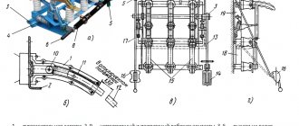
On the frame of the load switch 1, disconnecting springs 2 are installed, connected to a shaft 3. A wire lever 4 is installed on the shaft, to which the switch drive rod is connected. The drive rod and shaft are held in the operating position by the drive latch and the trip springs are compressed. When turned on, the load switch shaft rotates and the translational rotation of the porcelain rods 5 leads to the cutting of the knives of the moving contacts 6 into the fixed ones 7. The moving contacts are made in the form of two-way knives. Between the strips 8 there are arc extinguishing knives 9.
Extinguishing the electric arc during shutdown is facilitated by gases released from the organic glass of the liners located inside the plastic body of the arc-extinguishing chamber 10.
The main technical data of load switches VN-16 are given in the table below:
Application
The area of application of the load switch is mainly networks of voltage class 6 and 10 kV. The use of these switching devices is due, first of all, to savings: HVs are much cheaper than full-fledged high-voltage protective devices, and also require significantly less maintenance and repair costs.
Where are these pieces of equipment used? HVs are an alternative - they are used to switch currents on the high-voltage side of power transformers. But only if there are in the transformer connection circuit, as mentioned above, fuses or protective elements of equipment at the other end of the line from the adjacent supply substation or line switches from which the switchgear feeding this transformer is powered.
Load switches are used in other low-power networks as an independent switching device. On long and branched overhead lines, devices are used to conveniently disconnect sections of lines without the need to completely de-energize them. In this case, a switch is installed at the supply substation to protect the entire line from damage.
Purpose of disconnectors RLK, RLKV
Linear disconnectors for voltage 10 kV RLK (horizontal installation) and RLKV (vertical installation) are used to turn on and off energized but de-energized network elements.
If there are grounding blades on the disconnector, it is possible to ground the disconnected areas. RLK 10 kV linear swing disconnectors for external installation are necessary for safety when performing specialist work and allow you to perform various complex works to restore the functioning of electrical equipment after a failure.
Design
Let's look at what a load switch consists of using the example of a switching device type VNR-10/400
- Base (frame).
- Support insulator.
- Holders with contacts.
- Movable working knife.
- Arc extinction chamber.
- Fixed top contact.
- Isolating traction.
- Lever arm.
- Flexible communication.
- Grounding knife.
- Ground shaft.
- Locking device pull.
- Springs.
- Rubber gaskets.
- Shaft of working knives.