Operating principle
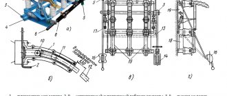
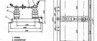
Let's take a brief look at how load switches work using the example of the above-mentioned VNR-10/400, shown in the photo:
Structurally, this switching device is similar to a disconnector. The main difference between a disconnector and a HV is that the latter has an arc extinguishing device and a drive, which ensures faster execution of operations.
The operating principle of the load switch is as follows. In the on position, the moving contacts are located in the arc chute. At the bottom of the arc extinguishing device there are additional arc extinguishing contacts. When performing a tripping operation, the main contacts are opened first, followed by the arcing contacts. The electric arc formed during the breaking of the contacts enters the arc-extinguishing chamber, where it heats the plexiglass to a high temperature, which in turn releases a large amount of gases. These gases burst out of the arc-extinguishing chamber in a powerful stream, thereby extinguishing the resulting electric arc in a few milliseconds.
How is VN depicted on single-line diagrams? Below is a symbol in the diagram:
On the left in the diagram is a VN, on the right is a switching device, which is structurally equipped with fuses (VNP).
So we looked at the device, purpose and principle of operation of the load switch. We hope that the material provided was useful and interesting for you!
We also recommend reading:
- How does a voltage relay work?
- What is an air circuit breaker
- What is a cam switch used for?
Marking of load switches
Each electromechanical device has its own marking, and the circuit breaker is no exception.
The marking consists of letters and numbers that indicate the location of the drive, voltage, current and other characteristics. For example, the designation of a 10 kV load switch VNRp 10/400-10зп stands for:
- B – switch;
- N – load;
- P – manual drive;
- P – built-in fuse;
- 10 – voltage 10 V;
- 400 – current 400 A;
- 10 – through current;
- Z – presence of grounding knives;
- P – arrangement of knives behind the fuse.
Other models are written in a similar way.
Types of switches
There are several types of devices, which are installed depending on the number of networks and consumers.
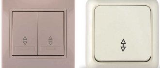
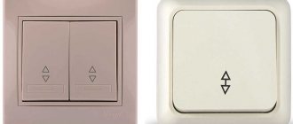
- Single pole.
- Bipolar.
- Three-pole.
- Four-pole.
Single-pole and double-pole devices are used in single-phase networks, and the rest are used in three-phase networks. The single-pole type of device is a very common option. Such a device is equipped with one module for transmitting the direction of electricity flow. In such models, copper conductors are most often used. Such a reversing switch is considered most suitable in the generator service network with a range of up to 20 Hz. When choosing such a device for a particular network, you need to take into account all the characteristics.
It is better not to use it in residential buildings, which are characterized by high electricity consumption, since the maximum load of such a device is considered to be 200A. The device also has a low output voltage. In most cases, this figure is about 200 V.
For use in residential buildings, two-pole switches are used. This type of device can be used with single-phase network consumers. The average resistance value for this type of switch is considered to be 60 ohms. Most often, such a two-way changeover switch is used for modern consumer electrical circuits. The modification of the device determines the output voltage, and in different two-position models the indicators will differ.
Reversible devices, which are used to change power from the network or generator, are connected according to different schemes depending on the specific type of network and the number of devices. For example, in a single-phase network, you can connect two-pole switches with a negative resistance of 50 Ohms. In this case, the circuit may contain an electric meter. A reversible three-phase switch is most often found in two-phase electrical networks, although it can also be used in a single-phase network. In this case, only two poles of the device will be used.
However, when connecting, you need to take into account that the three-way switch is equipped only with expansion switches. The most common three-position device in industrial electrical networks. Use in enterprises must be protected, so the connection must be made in electrical panels. The three-phase switch has a high sensitivity threshold and is equipped with a reliable overload protection system. The type and quality of insulation depends on the manufacturer.
Double capacitor switch
A double-pole type switch has two pass-through capacitors. Such devices can only be used in a single-phase network, so it is better to choose this type of changeover switch for a generator. There are also two-module and three-module types of devices on the market that can be connected to a power supply.
Changeover switches with a threshold voltage of 350 V are suitable for the generator. Load parameters may vary. This parameter is determined by manufacturers and most often is about 30 A. For the generator, you can also use a 250A changeover switch. However, such a device must be connected together with a power supply, the voltage of which will be from 200 to 300 V. This type of device provides a load of up to 3 A.
Connection of any type of device must be carried out in compliance with polarity. In this case, at the output to the home network, phase and zero should not change places. Incoming electrical connections are best protected by installing a circuit breaker. Such a switch is usually installed near the meter or in the changeover switch panel itself.
Switch ABB OT63F3.
This is the most common ABB switch, which is widely used both in everyday life and in production. Very reliable, can be installed on both DIN rail and mounting panel.
It is sold as a standard 3-pole, but you can either immediately buy a 4-pole OT63F4N2 or buy an additional pole separately and “increase” the switch yourself. Or maybe even two extra ones. click the poles, one on the right, the other on the left, and you get a 5-pole ABB switch)).
This ABB OT63F3 , as the name suggests, is designed for a current of 63 A. In this series of load switches there are switches that are designed for lower currents of 16, 25 and 40 A, but they differ in size and “become” in electrical panels, to put it mildly clumsily, which is clearly visible in the photo borrowed from my famous colleague Cs-Cs.net.
Of course, there are ABB switches of the OT series and higher 63A. ABB produces low-voltage load switches up to 2500 A, but we don’t need them; such loads don’t happen in everyday life.
Perhaps one of the disadvantages of the OT63 switch is its “original” handle, with which it is sold. For me, it is very inconvenient and switching the ABB switch is very inconvenient for her, especially for those who do not have very strong fingers, for example, children and women.
This problem can be solved quite simply; you can buy and install separately a handle of a slightly different design, but very comfortable. Such handles come in two colors: black and red, which, by the way, is also sometimes convenient, so that the tasks of the switches in the shield are clearly understood. For example, an ABB switch with a red handle turns off generator lines, and a black handle turns off ordinary NON-generator lines.
The ABB OT63 switch, as I previously wrote, is very reliable, one might say indestructible and quite practical in the sense that it externally fits into switchboards of all manufacturers, including Schneider Electric and Legrand.
The difference between machines by the number of poles
The complete set of circuit breakers includes up to four poles. To purchase a suitable device, it is enough to understand the types of electrical machines, the purpose and characteristics of each of them:
- One pole. Designed for safety in the electrical network that supplies power to regular outlets and lighting in the home. Installed on the phase wire, excluding the capture of the neutral wire.
- Two poles. They are connected to a circuit that supplies power to household appliances that require high energy consumption. This category includes electric stoves, washing machines and others.
- Three poles. They are installed in semi-industrial networks that provide power to powerful devices such as well pumps or installations for a car workshop.
- Four poles. They ensure network safety from overloads and short circuits, allowing you to connect four cables to it at once.
Devices are selected only depending on their area of application.
Purpose of load switch
A load break switch is a switching device that is equipped with an arc chute and a drive for control. The electric drive can be muscular, activated by a tensioned spring, or with a remote shutdown solenoid. The main purpose of the device is to mechanically open or close a circuit in an area that is under load. It is designed to cut off emergency currents, which is why installation is permissible only if there is protection against overload and short circuit.
Any load switch consists of the following parts: a spring mechanism, power contacts, grounding blades, a disconnector with poles. The poles are placed in the frame. The main moving contact consists of 2 steel plates. A special copper contact is used to extinguish the arc. The mechanism is turned on and off using tensioned springs. A detailed description of the design will be considered using the example of the VNR 10/400 model. It contains:
- frame;
- support insulator;
- workers grounding knives;
- holder with contacts;
- extinction chamber;
- isolating rod and locking device;
- grounding shaft and working knives;
- lever arm;
- springs;
- internal gaskets.
Specifications:
- fastening method;
- rated current;
- additional options;
- equipment;
- design;
- Rated voltage.
The main area of use is networks of voltage class 6 kV and 10 kV. Such devices are used in power transformers, lifting machines, laundries, catering facilities, car washes and other important facilities operating under high voltage. Manufacturing companies use similar devices in their plants and factories, but they are more expensive and have more functionality.
Sudden shutdown of the mechanism
Experts have recorded a lot of cases when the circuit breaker tripped. This situation requires a quick response from the master. To prevent negative consequences, experts have identified the main list of reasons that provoke the mechanism to turn off:
- Changing previously specified characteristics.
- A sharp decrease in voltage in the electrical circuit.
- Failure of machines or unexpected failure in the system.
- A sharp increase in voltage, a change in current state.
Since there are so many negative factors in the household industry, all modern devices are now equipped with several working mechanisms that allow you to quickly disconnect the network. They are produced from mechanical, electromagnetic or electronic particles. Rational use of such a release helps keep all home appliances safe and sound.
How to install a two-pole circuit breaker instead of a package switch
First, let's take a look at the history before we tell you how to install a two-pole circuit breaker. In old buildings that do not have electric stoves, apartment
First, let's take a look at the history before we tell you how to install a two-pole circuit breaker.
In older buildings that do not have electric stoves, the apartment electrical panel is placed right at the entrance door to the apartment. The design of the switchboard is very simple - it is a rectangular metal frame with a base, which has a meter, a batch switch and circuit breakers (or plugs) attached to it.
Panels of this type were installed in houses built between 1947 and 1980 and were designed for a power of about 2 kW. This was enough for those years, but it does not suit the consumer in our time. It should be noted that the weakest point of such an electrical panel is the packet switch, which has a handle that turns in a circle. Such a package switch is designed to operate in electrical circuits with an operating current of about 16 amperes, which corresponds to a load power of 2.2 - 3.5 kilowatts.
With a slight excess of current in the circuit, such a “packet” burned out very quickly. Therefore, in the electrical panels of old houses, the issue of replacing the package switch very seriously arises, and users increasingly began to resort to the possibility of replacing the “package” with an automatic circuit breaker.
Before dismantling the batch switch, you should remove power from your electrical panel using the circuit breaker (plug) from which voltage is supplied to the apartment (located in a common “dressing room” with the neighbors, usually above the light bulb). In place of the removed “bag”, you should prepare holes for mounting a two-pole automatic distribution machine for 25 (40 - if there is permission) amperes, install it and carefully strengthen it.
The phase wire that approached the contact of the removed switch from the electric meter should be connected to the upper terminal of one pole of the new machine. The neutral wire is connected to the upper terminal of the second pole.
The phase wire coming from the packager to the linear machines, which remains unused after its removal, is connected to the lower terminal of the first pole of the machine being installed. The neutral wire in this pair is connected to the lower contact of the second pole.
Now you can turn on the common circuit breaker in the “anteroom” (insert the plug) and turn on the new circuit breaker. After this, voltage should appear in the entire apartment (if all linear circuit breakers are turned on).
Source
Parameters of time-current operation of automatic machines (A, B, C and D)
| Designation of protective characteristic (category) | Instantaneous short circuit shutdown (abbreviated) | Preferred Circuit Breaker Application | Loads on the area |
| B | (3-5) In | Protection:
| resistive |
| C | (5-10) In | Protection:
| resistive, inductive with low starting voltage |
| D | (10-50) In | protection:
| inductive with high starting voltage |
The main difference between a “machine” and a switch (switch)
A switch, or power disconnector, is a regular switch, only powerful.
Its task is simply to turn off the power on the line. There is virtually nothing in the device circuit except contacts; its design is durable and simple. The design of “automata” is more sophisticated, because functionally it is a more complex device with a larger area of responsibility. Automatic circuit breaker - protects the electrical circuit from overloads and short circuit overcurrents and is designed for a certain number of on-off cycles (depending on the manufacturer, series and model). For example, the wear resistance of the BZMB1-A100 device from Eaton (Moeller) is up to 10,000 cycles.
When there is a need to turn on and off the power grid daily, or even several times a day, using an “automatic machine” is irrational. By manually clicking sensitive equipment like a simple switch, you will exhaust its service life ahead of schedule and for other purposes. After all, the main function of the device is to automatically operate in emergency mode.
It is more logical to install a switch at the input for a simple “on/off”. Moreover, its cost is much lower. So, for a 250A load switch in an online store you will pay from 638 UAH, and for a circuit breaker of this rating, get ready to spend at least 1841 UAH.
Expert tip: It is recommended to use both input devices simultaneously.
Circuit breaker parameters
The main parameters of circuit breakers include:
- rated voltage of the circuit breaker;
- rated current of the maximum release;
- setting for the operating current of the maximum release;
- setting for the response time of the maximum release (only for selective circuit breakers).
Automatic machines of different models The rated circuit breaker is the current for which its main contacts are designed in continuous operation.
To disconnect short-circuit currents, maximum releases (overvoltage relays) are installed in the circuit breaker. The rated currents of overcurrent releases may differ from the rated currents of the circuit breakers. The setting for the operating current of the maximum release is considered to be the one at which the maximum release will turn off the machine. The setting for the AV operation current is usually given in relative units.
For your information! The tripping time setting for the overload release is the time between the moment the short circuit is detected and the moment the circuit breaker trips.
The principle of operation of the machines
Design and principle of operation
One of the main components of the machine is its power contacts. The VA is usually turned on manually - by pressing the power button or raising the control handle up. In this case, the spring mechanism is charged, and the elements of the contact group are pressed against each other with a certain force. Maintaining the cocked state of the spring mechanism is ensured by a locking latch that holds the mechanical drive in the on position.
Sectional view, typical approximate view.
Switching off can be done either manually or automatically when the circuit breaker protection device is triggered. In the simplest case, the protective functions are performed by two components - electromagnetic and thermal releases.
Electromagnetic release
The ER is a current coil (solenoid) with a movable electromagnetic core - the striker. The current of the powered electrical installation constantly passes through the coil. The solenoid operates at a certain value of the current flowing through the contacts of the machine. Usually this is a current value several times, or even orders of magnitude, greater than the rated value. When a short circuit occurs in the protected circuit, under the influence of emergency values, the solenoid rod extends and presses on the latch of the mechanical drive of the release. As a result of its release, the switch drive breaks the contact under the action of the spring force.
Thermal release
The thermal release usually consists of a bimetallic strip through which current flows. In fact, the current can flow not through the plate itself, but through a high-resistance conductor wound on it, heated by the current and transferring heat to the plate. A bimetallic strip is
thin strips of two metal alloys welded together. Materials are selected in such a way that their coefficient of thermal expansion has a large difference. This is necessary so that when the bimetal is heated, the plate bends - after all, one of its layers expands much more actively.
Further, when a certain critical bend is reached, the plate acts on the latch lock, turning off the switch. StabExpert.ru reminds that the system parameters are selected in such a way that heating of the plate begins when a current flows through it exceeding the nominal value by about 20%. In this case, the higher the current value, the more active the heating occurs, therefore, the faster the critical bend is reached and the machine is switched off.
Release difference
Summarizing the description of the operation of these two mechanisms, it can be noted that the electromagnetic type release is a current protection without time delay, which is called current cutoff
. The current cutoff reacts to overcurrents that occur during short circuits in the protected network.
The thermal release makes it possible to realize the integral dependence of the protection response time on the current value. Thermal protection ensures equipment shutdown when it is overloaded, when the consumed current is 20% or more greater than the rated current. Under these conditions, the cutoff does not yet operate, but long-term operation of the equipment in this mode is unacceptable.
Why combine a switch with a “machine”
At the household level, this ensures the convenience of managing the electrical network and the durability of the home electrical network, but the decision still depends on you. Do you plan to de-energize the line a few times a year, for example, only when carrying out emergency repairs? Then you can get by with the “automatic” lever.
If we are talking about the electrical network of an apartment building or an industrial building, which have increased safety requirements. First of all, place a switch at critical places on the input cable. It will work as a switching device, with the help of which the line is de-energized with one movement. Moreover, the device must have a visible circuit break, without protective covers.
For example, the P2M model from Elecon for 250A or the PE19 series disconnector from IEK in which, when the network is disconnected using a lever, a break in the contacts is visually noticeable - there are no covers or panels obscuring the insides of the structure. For what? So that when maintaining the network at the site, the person carrying out the work is 100% sure that the system is de-energized. But the design of the “machine gun” cannot provide this visual clarity, because the device body is closed.
The use of switches is advisable in industries where personnel must de-energize equipment at the end of the working day or before carrying out repair work. Or, for example, to turn on and off the perimeter lighting system.
We prepare the machine for connection and installation
As an example, we will take the two-pole circuit breaker mentioned above.
This machine has four contacts, two suitable, they are located on top.
There are two outgoing ones, they are located at the bottom of the machine.
The contacts have screws, with the help of which the pressure plates located at the end of the machine are driven.
The plates are designed to fix the wire.
As a rule, a diagram of its connection is drawn on the body of the machine. The designations indicate that the supply wires are connected from above (terminal 1.3), and the outgoing wires from below (terminal 2.4).
Also on the body of the machine is indicated the maximum operating current C 40, which means 40 Amperes, this is the current to which the machine is limited. In order to find out which machine you need, you need to calculate the wire cross-section.
The machine is mounted on a special rail (DIN rail).
For this purpose, a special latch is provided on the back of the machine.
This is what it looks like in the end.
Types of high-voltage load switches
The types of load switches are as follows.
Autogas:
BHA-10/630. This type of switch provides switching of three-phase electrical circuits for voltages of 6000 and 10000 V, the frequency of which is 50 Hz, under load. Automatic grounding of switched off lines is provided using special grounding knives. These device models are installed mainly at transformer substations, in distribution devices and in service boxes. The type of arc extinguisher is autogas; the drive can be either manual or electric. The units are designed for a twenty-five-year service life with intermediate overhauls every two thousand operations.
- VNB-10/630. The 10 kV high speed load switch is used in loaded circuits with current strength up to 630A. Its neutral wire is grounded or insulated. The units of application are one-way maintenance of stationary chambers, substations of transformer devices, complete distribution cabinets, they are also used to replace old modifications of switches. Arc extinguishing system using gas release.
- BHP-10/630. It works in a similar way to the BHA-10/630 switch, but the drive is only manual. Can be equipped with grounding contacts and additional fuses.
Vacuum:
- VBSK-10-20/1000. Load switches designed for voltages up to 12000 V, which are capable of switching electrical circuits (three-phase with isolated neutral) in normal operation modes and in emergency situations. The devices are used in all of the above systems, as well as when replacing low-oil switches. Switches of this type have small dimensions, therefore they are convenient for installation in different types of distribution boxes.
- BB\TEL. A universal disconnecting device, the arc extinguishing system of which is based on its attenuation in a deep vacuum. The electromagnetic mechanism fixes the arc extinguishing contacts when closed. These systems are distinguished by their long service life and high wear resistance. They are small in size and do not require repairs.
- BBT-10-20. Vacuum type circuit breaker with motor-spring drive, which is designed for the same purposes as VBSK-10-20/1000, but this load circuit breaker can only withstand 10 kV.
Disconnect devices:
- RVZ-10/630 are designed for switching purposes when working with high voltage, but no load currents. Using them, you can reconnect and change circuits, and repair work is carried out in a safe mode (de-energized lines). They have a drive design of a lever operating principle.
- RLND - perform the same functions, but are acceptable for installation outdoors.
How to distinguish a circuit breaker from a load switch
In principle, mini-switches and load switches are the same thing. They are freely sold in stores, but are in less demand than circuit breakers. Mini-switches are devices that are used for switching (turning on and off) circuits under load. They are manufactured in a modular design and are similar in appearance to conventional machines.
The question is often asked: “Why are mini-switches and load switches needed?” Moreover, they cost much more than the same circuit breakers. Let's try to figure this issue out here.
What is a load switch?
This is a device that allows you to quickly turn on or off any circuit under load.
Load switches have reinforced contacts, the service life of which far exceeds the service life of the contacts of simple circuit breakers. This is necessary to be able to safely de-energize a line that is under load. If you turn off the load with a conventional circuit breaker, the arc that forms when the circuit breaks can eventually cause the contacts to stick together. Therefore, conventional automatic machines cannot be used to switch the load on and off. They are needed to protect electrical wiring in the event of an abnormal situation in the power supply circuit they protect.
Also, some models of load switches have a double contact break, which ensures complete de-energization of the disconnected line.
In order to be able to visually verify that the contacts of the mini-switch have broken, some models have a special viewing window. Through it you can see in what state (closed or open) the switch contacts are.
For example, this is implemented by TDM. Here the window is located above the control knob. Also, such models have a protection function against accidental disconnection or activation of the mini-switch. On the front model there is a kind of screw for a slotted screwdriver, which is marked on the case “Block - 100A”. For example, we turned off such a load switch, turned the “Block-100A” bolt with a screwdriver, thus blocked the control handle and went to work safely. In order to turn this switch back on, you must remove the handle from the locked position.
An example of mini-switches in the old version are package switches that are located in front of electric meters in floor distribution boards.
What types of load switches are there?
They come in 1, 2, 3 and 4-pole types. You should choose depending on whether you have a single-phase or three-phase network and whether you need to break the zero with a switch. These load switches are installed on a standard DIN rail. This is very convenient, since they can be installed in any distribution panels.
According to the current rating, mini-switches are divided in the same way as automatic machines. This is for 16, 20, 25, 32, 40, 63, 80, 100, 125A.
Please note that the load switch does not protect against short circuits or overloads. Therefore, the line must be protected with a circuit breaker. You need to choose them like this: the nominal value of the switch should exceed the nominal value of the machine by one or two steps. It takes up to one hour for a circuit breaker to disconnect an overloaded line by 45%. During this time, the contacts of a mini-switch of the same rating as the machine will begin to heat up. Which won't be entirely good.
How to distinguish a load switch from a circuit breaker?
Externally, mini-switches look like automatic machines, so you need to be able to distinguish between them. Typically, the load switch is marked on the housing with the letters “VN”. The mini-switch also has a more massive, reinforced control handle, which immediately catches your eye.
Differences in the protective characteristics of C, B and D circuit breakers, areas of application of the circuit breakers
Contents of the current article:
- ;
- with characteristics B, C, D: ;
- ;
- ;
We supply BA47‑29 circuit breakers with rated currents from 0.5 to 63 amperes with protective characteristics B, C or D.
Introduction
Modular circuit breakers are used:
- to protect networks: from short circuits - an electromagnetic release is built in for this purpose;
- from overloads - a thermal release is built in for this purpose;
A thermal and electromagnetic release is installed in each pole of the machine and together they are called a combined release. Characteristic C, B or D determines the strength of the short-circuit current at which instantaneous protective operation will occur, and therefore the places where the machine with a specific characteristic will be used. The operation is caused by an electromagnetic release. On the left is a photograph of VM63 modular switches with an analysis of the inscriptions (“what is what”).
Differences between circuit breakers with characteristics B, C and D
| Type of protective characteristic | Instant shutdown in case of short circuit out of range | Preferred Circuit Breaker Application | Loads |
| B | (3-5)In | protection: - long cables; — networks with electric heating devices (stove, boiler); — low-power networks:
| resistive |
| C | (5-10)In | protection: — lighting; — sockets; — household electrical appliances. | resistive, inductive with low inrush current |
| D | (10-50)In | protection: — electric motors (washing machines, water pumps); — low-voltage transformers; - discharge lamps. | inductive with high starting current |
Values removed from table 2 on page 11 of the standard for modular circuit breakers GOST 50345‑99 (link below).
where In is the rated current of the circuit breaker. Examples:
- A circuit breaker with a rated current In = 6 amperes with characteristic B: will not trip* with a short circuit of 18 amperes (3·In), but will switch off instantly with a short circuit of 30 amperes (5·In) and above.
- A circuit breaker with a rated current In = 16 amperes with characteristic C: will not trip* with a short circuit of 80 amperes (5·In), but will switch off instantly with a short circuit of 160 amperes (10·In) and above.
- A circuit breaker with a rated current In = 50 amperes with characteristic D: will not trip* with a short circuit of 500 amperes (10·In), but will turn off instantly with a short circuit of 2500 amperes (50·In) and above.
*By the words “will not work” we mean will not work under the influence of an instantaneous electromagnetic release. But there is a thermal release that will heat up within a few seconds and turn off the network. At the same time, the standard does not indicate how the switch will behave in the range itself (the error is included). Tests are carried out only in boundary positions (according to table 6 on page 19 of the GOST 50345‑99 standard):
- lower limit (3, 5 and 10 from In, respectively) – shutdown does not occur within 0.1 seconds;
- upper limit (5, 10 and 50 from In, respectively) – protective operation occurs within 0.1 seconds.
Circuit breaker characteristic B
Switches with characteristic B are used for protection:
- long cable lines;
- circuits with a heating element (heating element, electric oven, boiler);
- secondary circuits or networks with high resistance and low current (which causes low-level short-circuit currents): alarms;
- management;
- measurements.
Characteristic C of circuit breaker
Automatic machines with characteristic C are used everywhere: in domestic and office premises, at industrial facilities. They help protect:
- apartment and office sockets;
- lighting in the kitchen, bedrooms; in the bathroom, in the office, in the workplace;
- individual consumers (without powerful engines).
Characteristic D of the circuit breaker
Switches with characteristic D are used to protect low-voltage transformers, electric motors or devices with them:
- washing machines;
- dishwashers;
- pumps for drinking water intake;
- welding machines.
- Standard for modular circuit breakers GOST 50345-99.
- on VM63 switches.
- Factory catalog for S800S switches.
Differences from circuit breaker
Automatic differential switch
At home, other devices are often used - automatic differential switches. They are installed on various household appliances to protect against power surges. They can de-energize the room if necessary, protect pantographs and wiring from the aggressive effects of high currents. Circuit breakers are not suitable for frequent trips and shutdowns. This can lead to rapid wear of the module and burnout of the working resource, after which the device will have to be replaced. For such purposes, it is recommended to use modular load switches. Input switches ensure high safety of distribution boards, uninterrupted supply of electricity, and ease of circuit breaking. The best option is to use a load switch and a machine at the same time. This increases the security of the electrical network.
The main difference from an automatic machine is the inability to operate in automatic mode. Switching requires external intervention - manual or remote. The machine is triggered when the maximum current is reached. Also, devices may differ in markings and appearance.
Source
General information about machines
Automatic switchboards
As a rule, automatic circuit breakers contain three types of electrical circuit releases: thermal, electromagnetic and mechanical. The first is designed to protect electrical circuits from overcurrent, the second - from short circuits in load circuits, the third - for operational switching of electrical circuits.
There are electrical circuit breakers that perform protective functions against overload and electric shock (ES). These are switches controlled by differential current with built-in protection against current overloads - difavtomats (DV).
Main technical characteristics of automatic circuit breakers (AB)
Ratings of machines for various electrical networks
Rated voltage is the value set by the manufacturer at which the AV’s performance is determined.
Rated current is the current established by the manufacturer that the AV is capable of conducting in continuous mode, in which the main contacts remain closed at the specified control ambient temperature (standard +30 °C).
The switch frequency is the industrial frequency for which the device is designed and to which the values of other characteristics correspond.
The rated maximum breaking capacity is the value of the ET, which can turn off the AV while maintaining its functionality.
The current limiting class is characterized by the shutdown time between the beginning of the circuit breaker opening and the end of the arc time. There are three classes of current limiting:
- the shutdown time of class 3 AB occurs within 2.5 – 6 ms;
- 2 classes – 6–10 ms;
- Class 1 – more than 10 ms.
There are several types of protective (time-current) characteristics of AV, the most popular are B, C and D
| Type of protective characteristic | Range of instantaneous tripping currents, reduced to the rated value of the current AB | Purpose |
| A | from 1.3In | To protect circuits in which temporary overcurrents cannot occur during normal operation. |
| IN | from 3In to 5In | To protect circuits in which minor temporary current overloads are allowed in normal operation. |
| WITH | from 5In to 10In | To protect circuits in which moderate temporary current overloads are allowed in normal operation. |
| D | from 10In to 20In | To protect circuits with significant temporary current overloads in normal operation. |
| K | from 12 I | For protecting industrial circuits using inductive loads. |
| Z | from 4 In | To protect industrial circuits using industrial electronic equipment as a load. |
Differential circuit breakers
Differential circuit breaker
Rated residual current IΔn – the value of the residual current specified by the manufacturer, at which the DV must operate under specified conditions.
Rated non-breaking residual current IΔn0 – the value of the non-breaking residual current specified by the manufacturer, at which the motor does not operate under specified conditions.
The rated differential maximum making and breaking capacity IΔm0 is the effective value of the alternating component of the expected differential current, which the DV can turn on, conduct and turn off.
There are three types of DV:
- S – with differential current response time delay.
- AC – operation is ensured with a sinusoidal alternating differential current, either applied abruptly or slowly growing.
- A – ensures operation with differential sinusoidal alternating current and differential pulsating direct current applied in an abrupt manner or slowly increasing.
Appearance and device
It is similar in size and shape to circuit breakers. You can distinguish it by the inscription on the front side of the switch. Instead of the inscription VA, it will be written VN (or VM-R (switch).
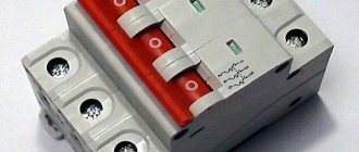
The modular load switch can be either single or 4-pole. It is produced for currents from 16A to 125A.
The main purpose of load switches is operational switching, i.e. the process of turning on and off rated currents in the outgoing circuit. A bridge contact is installed inside, with a larger area and greater pressing force than conventional machines.
From a safety point of view, using modular load switches in a switchboard is the right decision.
Manufacturers of circuit breakers usually indicate that the circuit breaker is intended for infrequent switching, usually no more than six times per hour.
Imagine that you often need to use a machine to turn off the lights.
Most of these switchings occur during the process of renovating an apartment or setting up lighting. Therefore, if you first have a switchboard installed, and then the repair itself takes place, be sure to take care of installing a load switch in the panelboard.
Here are the comparative characteristics of the electrical outage life of a conventional circuit breaker and a load switch of the IEK brand. As can be seen from the data, the load switch wins here almost 2 times.
Please note that switches cannot be repaired when used at home.
If any problem occurs with the modular device and a defect is discovered, do not try to disassemble and repair it yourself. So if you find a malfunction on the high-voltage switch or machine, replace them with others.
Peculiarities
There are no ideal systems; naturally, short circuiters and separators have a number of features, some of which can be considered disadvantages. For example, the latter sharply reduces the reliability of operation during glaciation. This problem is solved if closed-type disconnectors with SF6 gas filling are used. Such devices are more expensive than conventional models, but are still cheaper than power switches.
There are also complaints about short circuiters, in particular regarding their response speed (it is about 400-500 ms). The simplest solution in this case is to use structures that use a powder charge as a drive.
Otherwise, the operation of the devices described in the article is fully justified, as evidenced by the popularity of the OD-KZ combination.
Main technical parameters
Technical characteristics are taken into account when selecting and connecting the machine. The main ones are printed on the device body. There is often also a designation on the device diagram. The following characteristics stand out:
- Time-current characteristic. Indicated as the letter B, C or D. Machines with characteristics L, Z and K are less common.
- Rated current. The number indicated after the time characteristic.
- Operating voltage. Typically more than 400 V.
- Limit short circuit current. A large number is on the order of 1-35 kA. The maximum short-circuit current that the circuit breaker can withstand without destruction.
How to calculate the rating of a circuit breaker
How much electricity is needed for the operation of lamps and other products is noted in the accompanying documentation. Power is indicated on the housing. This data can be obtained from the manufacturer's official website. However, simply adding up kilowatts is not enough.
cos(f) – parameter with which you can determine the total (nominal) power from the active (consumed)
The simple calculation algorithm shown in the example describes the situation with a resistive load. It is this component (active power - P) that is indicated in the technical data sheet of the corresponding product. It is determined by the meter for regular payments for consumed energy.
Formulas and explanations:
- P = S * cos ϕ;
- Q = S * sin ϕ;
- S = P/ cos ϕ;
- ϕ – angle between vectors P and S (phase shift).
The reactive component (Q) denotes the cyclic exchange of energy between the power source and the load. The sum of the vectors P and Q will help determine the final apparent power (S).
Turning on a powerful pump (another reactive load) is accompanied by an inrush of current and a subsequent oscillatory process with a transition to normal operating mode. The pulse duration, as a rule, does not exceed 1.5-2 seconds. This duration is not sufficient to heat up the bimetallic plate. But this may be enough to move the solenoid rod.
The list shows typical over-rated levels that trigger tripping by the solenoid coil. The time delays before the bimetallic plate breaks the circuit (seconds) are given in parentheses:
- A – 30% (20-30);
- B – 200% (4-5);
- C – 5 times (1.5);
- D – 10 times (0.4).
This correction factor (Ks) is used to take into account loads under real operating conditions: Design = S * Ks. Its value (interval from 0 to 1) indicates the number of connected consumers. This method is convenient to use when creating office and industrial projects, which involve the use of the same type of equipment: machines, computers, etc.
Measuring voltage with a multimeter
The given formulas with phase shift are used to correct inductive and capacitive loads. Resistive ones are taken into account according to passport data without recalculation. The cos ϕ value is taken from the accompanying documentation.
The current can be calculated as follows:
- P/U – constant power supplies, resistive loads;
- P/ (U * cos ϕ) = P/ (220 * cos ϕ) – one phase, ~220V, consumer reactive characteristics;
- P/ (U * √3 * cos ϕ) = P/ (380 * 1.7321 * cos ϕ) – three-phase network ~380V, inductive (capacitive) technical parameters.
Selection of core cross-section
The necessary information about load capacities is contained in the official documentation of cable manufacturers. It is recommended to select a larger cross-section from the serial range to prevent overheating and damage during operation. According to current rules, conductors with an area of 1.5 mm or more are suitable for residential premises.
The limit value of the nominal value is determined by the formula Ir ≤ Ipr/1.45, where Ipr is the permissible current in long-term mode for a certain wiring. If you plan to install a network, proceed as follows:
- clarify the consumer connection diagram;
- collect passport data of equipment, measure voltage;
- according to the presented diagram, they are calculated separately, the currents in individual circuits are summed up;
- for each group it is necessary to select a machine that will withstand the appropriate load;
- determine cable products with a suitable conductor cross-section.
If the networks are installed in grooves and covered with plaster, disassembly is too difficult. In this case, select the machine according to the cable cross-section. They start by assessing the load capacity of existing lines. The obtained result is used to evaluate suitable models of protective devices. Next, consumers are distributed into groups taking into account the total power (shared use).
An example of choosing the machine's nominal value for each line
For correct conclusions, it is necessary to take into account the characteristics of the connected equipment. If the total current is calculated to be 19 amperes, users prefer to buy a 25A device. This solution assumes the possibility of applying additional loads without significant restrictions.
Different response times are useful to ensure selective operation of protective equipment. Devices with lower latency are installed on the lines. In an emergency, only the damaged part is disconnected from electricity. The input machine will not have time to turn off. Power supply through other circuits is useful for maintaining lighting, alarms, and other engineering systems in working order.
Short circuit and separator device
Let's briefly talk about the design of the electromechanical devices shown above, this will be useful in explaining their operating principle. Let's start with the separator; its simplified drawing is presented below (Fig. 3 1).
Figure 3. 1) separator design; 2)short circuit design
Designations (part 1 separator design):
- A1 – insulating posts.
- B1 – rotating rods with knives installed in contacts.
- C1 is a spring mechanism that drives the rotary rods.
- D1 – platform.
- E1 – a cabinet with an electromagnetic “trigger” mechanism that releases a spring drive that separates the contact parts.
Both the devices themselves and the mechanics of their operation are not complicated. We have already mentioned that the separator is used when the voltage is removed from the network, that is, when the switches on the supply line are turned on. Consequently, there is no need to install special vacuum arcing contact chambers on the disconnectors.
Now let's look at the main design elements of the short circuit (Fig. 3 2):
- A2 – main (support) insulator rod.
- B2 – fixed rod with contact knives.
- C2 – spring drive.
- D2 – platform on which the short circuit is installed.
- E2 – cabinet for electromagnetic drive and current transformer.
- F2 is a movable grounded rod that closes the poles of the short circuit.
Structurally, the KZ-35 short circuiter, as well as other models that create an artificial interphase short circuit, have several differences from the device shown in the figure. Since a linear short circuit is simulated, the movable one is not connected to the ground, it is connected to another phase. Accordingly, the structure is equipped with another insulator-rack.
